Table of Contents
Advertisement
Quick Links
Advertisement
Table of Contents

Related Manuals for GRIDFREE BACH KIT


Summary of Contents for GRIDFREE BACH KIT
- Page 1 BACH KIT INSTALLATION MAUNAL HYBRID...
-
Page 2: Warning - Read Carefully
WARNING - READ CAREFULLY While this manual seeks to be as comprehensive as possible, some aspects are not covered due to the different requirements for each installation. We recommend consulting the applicable standards for all installations. These may include: - AS/NZ 3000 - AS/NZ 4509 - AS/NZ 5033 - AS/NZ 5139... - Page 3 BACH KIT HYBRID Only some steps in this kit are under the 120V DC standards for extra-low voltage (ELV). ELV is an electricity supply voltage in a range which carries a very low risk of electrical shock. All steps after the section “Battery Wiring” are 240V AC and will require an electrician.
-
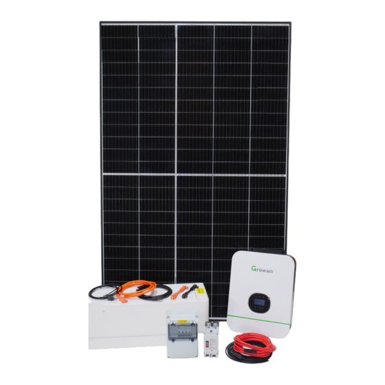
Page 4: Kit Contents
KIT CONTENTS 4x PERC MONO Solar Panel 4x 12v200Ah Deep Cycle Gel Battery 1x Growatt 5KW Hybrid Inverter - SPF 5000TL... - Page 5 1x 32A Solar 1x 200A Hybrid 1x 2-Way MCB PV DC Circuit Inverter DC Enclosure Breaker MCCB 1x 35mm² Cable 3m Pre-Crimped (Red + Black) 1x 35mm² Cable 1m Pre-Crimped M6 + M8(Red + Black) 3x 50mm² 30cm Battery Link Cable 1x 6mm²...
-
Page 6: Required Tools
REQUIRED TOOLS Screwdrivers Drill Wire Strippers Wire Cutters 6mm Allen Key 13mm Spanner Socket Set SOLAR MOUNT OPTIONS Ground Tilt Corrugated L-Feet... -
Page 7: Wiring Overview
WIRING OVERVIEW Generator/Mains Input Mains Distribution Box 200A Hybrid Inverter DC MCCB 32A Solar PV DC Circuit Breaker... -
Page 8: Solar Panel Wiring
SOLAR PANEL WIRING PV Inline Fuse Start by creating two pairs of panels wired together. Connect the positive terminal of one panel to the inline fuse, then to the negative terminal of the next panel. - Page 9 Y-branch connectors Connect the Y-branch connectors to one of the solar panel pairs.
- Page 10 Connect the other pair of solar panels to the Y-branch connectors, connecting the negative terminals from each pair with the black Y-branch connector, and the positive terminals from each pair with the red. This creates two outputs from the solar array: one positive (+), one negative (-).
- Page 11 DO NOT connect the cable run to the solar panels until all solar wiring is complete. Run the solar cables to the C32 circuit breakers, and cut it to length. Run the 6mm PV solar cables from the solar panels back to the C32 circuit breakers, and cuit it to length.
- Page 12 Indicator is green, showing the circuit breakers are switched off Ensure the solar cable run is NOT connected to the solar panels, and the circuit breakers are switched off (green indicator, switch down) Use wire strippers to strip the ends of the solar cable, and terminate them in the circuit breaker by inserting the stripped end and tightening the screw clockwise.
- Page 13 Connect the cable run to the solar panels Ensure the circuit breaker is switched off When the cables have been terminated in the circuit breaker and the circuit breaker is switched off, you can now connect the solar panels to the cable run. The circuit breaker must be switched off when connecting or disconnecting the solar panels from the cable run.
- Page 14 Tiny House kit Hybrid Manual - Charge Controller and Inverter Wiring- Page 11 HYBRID INVERTER WIRING Run the excess 6mm positive(+) and negative(-) cables from the C32 circuit breaker to the hybrid inverter.
- Page 15 Before proceeding to connect the hybrid inverter to the 200A MCCB circuit breaker, align the 35mm² x 1m cables between the components to ensure that the M6 ends (smaller holes) are inserted into the hyrbid inverter, and the M8 ends (larger holes) are inserted into the circuit breaker.
- Page 16 Ensure all circuit breakers are switched off before wiring (switch down, indicator showing green. Tiny House kit Hybrid Manual - Charge Controller and Inverter Wiring- Drawing 1, Page 13 Wire the positive(+) 35mm M6+M8 cable from the hybrid inverter to the 200A MCCB circuit breaker.
- Page 17 Tiny House kit Hybrid Manual - Charge Controller and Inverter Wiring- Drawing 2, Page 13 Wire the negative(-) 35mm M6+M8 cable from the hybrid inverter to the 200A MCCB circuit breaker.
-
Page 18: Battery Wiring
BATTERY WIRING 30cm Battery Link Cable The battery bank is wired with four 12V batteries in series. This creates a 48V battery bank. The large gauge cable is used to connect the batteries together in series. Wire the four batteries together from negative to positive with the blue battery link cable. When wiring the blue cables, ensure that you fully attach each cable at both ends before moving onto the next. - Page 19 Once you have wired the batteries into the hybrid inverter, your completed wiring should look like the image above (excluding the panels). Double check everything is wired correctly and tightened before proceeding to prevent damage to your system. Further steps will legally require an electrician.
- Page 20 Weekend Warrior kit Hybrid Manual - Battery Bank Setup and Wiring- Page 16, Drawing 1 If using the utility / generator input, use components rated for 50A. If using components rated for less (e.g. a caravan plug), make sure to use an appropriately sized breaker.
-
Page 21: Startup Procedure
STARTUP PROCEDURE Switch on the circuit breakers in the following order: i) Battery to hybrid inverter breaker 200A DC MCCB. ii) Panels to C32 circuit breaker. The green LED on the PV Charge should be flashing, and the panel voltage should be around 60V-80V in full sunlight. - Page 22 Weekend Warrior kit Hybrid Manual - Start up Procedure Page 18, Drawing 1 WIFI/GPRS NC C NO PV INPUT AC INPUT INPUT RS485 BREAKER DC INPUT AC OUTPUT Weekend Warrior kit Hybrid Manual - Flick the switch located at the bottom of the hybrid inverter to “ON”, and refer to the Start up Procedure hybrid inverter manual to ensure normal operation.
- Page 23 GETTING THE MOST OUT OF YOUR KIT Battery 48.9v To get the most life out of your batteries, they should not be discharged lower than 50%. You can check the state of charge of the batteries on the charge controller. Make sure the charge controller is on the screen shown above by pressing the “SELECT”...
-
Page 24: Battery Care Information
BATTERY CARE INFORMATION What is Battery Cycle Life and Depth of Discharge? Depth of Discharge is how much energy is discharged from the battery before it is charged to 100% again. A typical measurement is battery cycle life at 50% D.O.D (Depth of Discharge). At 50% DOD, the battery has 50% of its energy capacity discharged before it begins charging again. - Page 25 What happens if I over-discharge batteries? OVER-DISCHARGING is a problem caused by insufficient battery capacity resulting in the batteries being overworked. Discharges deeper than 50% significantly shorten the Cycle Life of a battery. Infrequent or inadequate recharging can also cause rapid sulfation –...
-
Page 26: Troubleshooting Guide
TROUBLESHOOTING GUIDE We’ve compiled this list of common problems our customers may encounter with their solar gear to help you solve any issues as fast as possible. Please contact us if you don’t find the answers you need here or if your issue continues after implementing the given solutions. - Page 27 5. My batteries drain very fast when the sun goes down The controller may read 100% while charging at the higher voltage, but it will quickly drop lower when no charge is applied. This could be because the batteries charge at a higher voltage, so when the sun goes down, the battery voltage will stabilise at a lower level.
- Page 28 CONTACT US Our website: gridfree.store Email us: info@gridfree.store Message us on Facebook: @GridFree.Store Give us a call: (09) 218 5533 Address: By Appointment– C4/27 Smales Road, East Tāmaki, Auckland, 2013 Hours: 9am-5pm, Monday-Friday Kit viewings, demos, and pick ups at Auckland warehouse by appointment only.
- Page 29 NOTES...
Need help?
Do you have a question about the BACH KIT and is the answer not in the manual?
Questions and answers