Table of Contents
Advertisement
Quick Links
Advertisement
Table of Contents

Related Manuals for Siemens SICHARGE D 8EM5907-0AA000-1AA7.05


Summary of Contents for Siemens SICHARGE D 8EM5907-0AA000-1AA7.05
- Page 2 SICHARGE D Introduction Safety instructions Description Transport and storage SICHARGE D Installation and mounting Commissioning Operating Instructions Operation Behavior in the event of errors and error messages Maintenance and service Decommissioning and disassembly Disposal Technical specifications Declaration of Conformity List of abbreviations and explanation of terms Checklist for commissioning...
- Page 3 Note the following: WARNING Siemens products may only be used for the applications described in the catalog and in the relevant technical documentation. If products and components from other manufacturers are used, these must be recommended or approved by Siemens. Proper transport, storage, installation, assembly, commissioning, operation and maintenance are required to ensure that the products operate safely and without any problems.
-
Page 4: Table Of Contents
Table of contents Introduction ............................6 About the operating instructions ..................6 Basic information ......................... 7 Open-source software ......................8 Safety instructions ..........................9 General ..........................9 2.1.1 Intended use, modifications to the device ................9 2.1.2 Qualified personnel ......................10 2.1.3 Protection against unauthorized opening ................ - Page 5 Table of contents Display elements and operator controls ................29 Charging ports ........................35 Design of the charging station ................... 38 Dynamic power distribution ....................41 Electrical protection devices ....................43 Self-checks & health monitoring ..................44 3.10 External Emergency Stop ....................45 3.11 Connection to an external load management system ............
- Page 6 Table of contents Commissioning ............................ 97 Safety precautions before initial commissioning ..............97 Switch on charging station ....................97 Switching off the charging station ..................99 Restarting the charging station ..................99 Service mode ........................99 Operation ............................100 Safety instructions ......................100 Starting the charging process ...................
-
Page 7: Introduction
Introduction About the operating instructions These operating instructions contain the information necessary for the safe operation and intended use of the SICHARGE D charging station and are aimed predominantly at operators of the charging station. Together with the documentation listed under Appendix (Page 133), they form the basic documentation of the SICHARGE D. -
Page 8: Basic Information
Introduction 1.2 Basic information Changes compared to the previous version Compared to the 01/2022 edition, this manual contains the following changes: • Change to the article number • Adaptation of the nameplate • Note on use of the cable bridge for TN-C systems •... -
Page 9: Open-Source Software
Siemens accepts no liability for the use of the open source software over and above the intended program sequence, or for any faults caused by modifications to the software. -
Page 10: Safety Instructions
Safety instructions The safety instructions section describes the intended use by the target groups and potential dangers. General 2.1.1 Intended use, modifications to the device Intended use The SICHARGE D charging station has up to three ports for charging the batteries of electric vehicles. -
Page 11: Qualified Personnel
Alterations to the device The operating instructions describe all permissible alterations to the charging station. Any other or additional alteration that is not included in this or another official Siemens document is not permitted. This applies to both electrical modifications (connecting, disconnecting or swapping connections of electrical devices, etc.) and mechanical modifications (e.g. -
Page 12: Protection Against Unauthorized Opening
Safety instructions 2.2 Hazards during transport, mounting, operation and maintenance 2.1.3 Protection against unauthorized opening A lock system protects the charging station from unauthorized opening of the device doors at the front and back. • Keep the key for the door locks safe against access by unauthorized persons. •... -
Page 13: Fall Arrester
Safety instructions 2.2 Hazards during transport, mounting, operation and maintenance 2.2.2 Fall arrester When working at heights above 1 m, use a fall arrester. Use work platforms or lifting platforms to provide qualified personnel with a stable surface. Take the necessary precautions to prevent tools and components from falling. -
Page 14: Risk Of Crushing Or Cuts
Safety instructions 2.2 Hazards during transport, mounting, operation and maintenance Accident hazards Avoid accidents and injuries to persons, as well as damage to vehicles and the SICHARGE D. Accident hazards include: • Inattention • Danger of tripping or slipping. • Vandalism Provide additional protective measures, such as: •... -
Page 15: Hazards In The Event Of Fire, Explosions And Emergencies
Safety instructions 2.3 Hazards in the event of fire, explosions and emergencies Hazards in the event of fire, explosions and emergencies Fire and explosion protection Do not store or use flammable liquids that produce flammable vapors, such as gasoline or ethanol, in the vicinity of the charging station. -
Page 16: Dangers Due To Electrical Current
Safety instructions 2.4 Dangers due to electrical current Dangers due to electrical current 2.4.1 Protection against ingress of liquid The IP54 degree of protection of the cabinet protects the charging station from ingress of water splashing against it from all directions. The protection standard prevents ingress of precipitation and any liquid not under pressure that comes into contact with the enclosure surface. -
Page 17: Electric Shock Due To Lack Of Grounding
Safety instructions 2.4 Dangers due to electrical current Securing an electrical system before starting work Before starting work on and in electrical installations, apply the following five safety rules: 1. Disconnect at electric distributor 2. Secure against reconnection at electric distributor 3. -
Page 18: Danger To Life And Damage To Property Due To Loose Power Connections
Safety instructions 2.4 Dangers due to electrical current 2.4.5 Danger to life and damage to property due to loose power connections Insufficient tightening torques and vibrations result in loose power connections. Loose power connections can result in high voltages on exposed parts. Touching the parts can lead to severe injuries or death. -
Page 19: Dangers From Electric Fields
Safety instructions 2.5 Dangers from electric fields Dangers from electric fields 2.5.1 Pacemakers/implants No dangerous radiation emanates from the charging station. Interference with pacemakers and implants is excluded. 2.5.2 Electromagnetic fields The charging station meets the requirements of IEC 61851-21-2:2018: •... -
Page 20: Safety Sign
Safety instructions 2.6 Safety sign Safety sign Safety signs are attached to the charging station and on the packaging for safe handling of the charging station. Safety signs on the packaging Safety sign Meaning Warning of general danger Safety sign in the charging station Safety sign Meaning Warning of dangerous voltage... -
Page 21: Identification Of The Device
Safety instructions 2.7 Identification of the device Identification of the device The nameplate clearly identifies the charging station and is located in the bottom right corner on the left-hand cabinet wall and at the top inside the front door (see Figure 2-1). The nameplate also contains the identification data of the device, information about the manufacturer and the CE marking. - Page 22 Safety instructions 2.7 Identification of the device Figure 2-3 SICHARGE D nameplate (newer hardware release) SICHARGE D Operating Instructions, 11/2022, 8EM5907-0AA00-1AA7.05...
-
Page 23: Safety Loop And Emergency Stop
Safety instructions 2.8 Safety loop and emergency stop Safety loop and emergency stop The emergency stop of the charging station is triggered when the safety loop of the charging station is interrupted. The safety loop includes by default the door contacts on the front and rear. - Page 24 Safety instructions 2.8 Safety loop and emergency stop Function of the switch The function of the switch is described in detail in section 3.3 "Display elements and operator controls" (Page 29). Revoking the Emergency Stop Note Eliminate the hazardous situation First eliminate the hazardous situation when you want to revoke the Emergency Stop.
-
Page 25: Industrial Security
Siemens’ products and solutions undergo continuous development to make them more secure. Siemens strongly recommends that updates be applied as soon as they are available and that the latest hardware and software versions be used. Using versions that are obsolete or are no longer supported can increase the risk of cyber threats. -
Page 26: Description
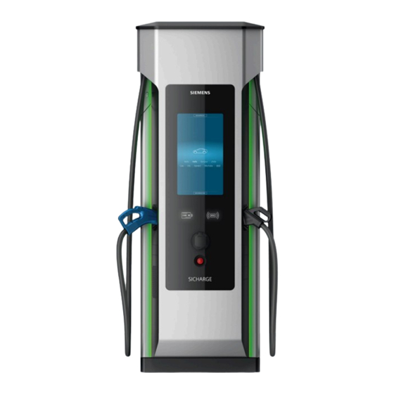
Description Product overview The SICHARGE D charging station is designed for rapid charging of electric vehicles. It supports the DC charging standards CCS and CHAdeMO and AC charging Mode 3. This means that nearly all vehicle models from various manufacturers can be charged quickly and efficiently. - Page 27 Description 3.1 Product overview Application The charging station is designed for charging electric vehicles in public and semi-public commercial and industrial areas, e.g: • Inner cities • Parking garages • Terminals • Vehicle depots • Company parking lots Compatibility Only vehicles that meet the following standards can be charged at the charging station: Table 3- 1 Compatibility overview Type...
-
Page 28: Configuration Options
Description 3.2 Configuration options Configuration options The following table shows the various selection and equipment options of the SICHARGE D. not available for ERK compliant metering SICHARGE D Operating Instructions, 11/2022, 8EM5907-0AA00-1AA7.05... -
Page 29: Scope Of Supply
Description 3.3 Scope of supply The descriptions in the following sections always reflect the maximum configuration of the charging station. The figures below may contain options and special equipment. Scope of supply The following components are also included in the scope of delivery of every charging station: Description ①... -
Page 30: Display Elements And Operator Controls
Description 3.4 Display elements and operator controls Display elements and operator controls The charging station has the following display elements and operator controls: ① Touch screen ⑦ Emergency Stop switch ② LED strips ⑧ Viewing window for AC meter of the AC charg- ing outlet ③... - Page 31 Description 3.4 Display elements and operator controls LED strips The LED strips signal the state of the charging station or the individual DC charging outlets. In this way, the user can recognize from a distance if the charging station is free, the vehicle is fully charged or there is an error.
- Page 32 Description 3.4 Display elements and operator controls DC meters The window with the display of the DC meters of the respective charging outlet on which the released energy can be read is located below the plug holder. Please refer to the operating instructions on the use of the device for more information on the contents displayed.
- Page 33 Description 3.4 Display elements and operator controls Locking system & replacing the lock cylinders The door locks and the door opener secure access to the inside of the charging station. At the front, the lock cylinder is in the cover at the top left next to the device door. Unlock the lock and remove the cover by pushing it upwards.
- Page 34 Description 3.4 Display elements and operator controls There are two additional locking cylinders of the same type on the back of the charging station in the two swiveling levers. Unlock the levers to deflect them. Remove the fixing screw in the deflected lever to replace the locking cylinders here as well. Proceed in the same way as for the front side.
- Page 35 PIN entry or similar is not required. The operations of the transaction are shown on the charging station display. For information on commissioning and operation of the credit card terminal, please refer to document 8EM5907-0AA00-7AA4 Credit card terminal (https://support.industry.siemens.com/cs/us/en/view/109814747). SICHARGE D Operating Instructions, 11/2022, 8EM5907-0AA00-1AA7.05...
-
Page 36: Charging Ports
Description 3.5 Charging ports Charging ports The DC cables mounted on the charging station have the charging plug type CCS or CHAdeMO. These two types differ primarily with respect to their connectors and the number and usage of the individual pins. CCS plug (Combo 2) Figure 3-6 CCS plug (Combo 2) - Page 37 Description 3.5 Charging ports CHAdeMO plug Figure 3-7 CHAdeMO plug Table 3- 4 Pin assignment of the CHAdeMO plug Contact ① Protective Earth (PE) Protective conductor ② Signal 1 Initialization of the charging process ③ ④ Signal 2 Release/lock the charging process ⑤...
- Page 38 Description 3.5 Charging ports Interlock To guarantee secure charging, the charging plug and charging socket cannot be disconnected under load. After plugging in and initiating the charging process, an electromechanical actuator automatically locks the plug-in connection in the vehicle inlet or the AC charging socket.
-
Page 39: Design Of The Charging Station
Description 3.6 Design of the charging station Design of the charging station The cabinet is made of powder-coated steel. It is painted in RAL 9006 as standard. The charging station is subdivided into five different areas. Four areas are arranged above one another, while the molded door represents the fifth area. - Page 40 3.12 "Routers" (Page 47). The following figure shows the interior view of the door. ① Customer router, Router 2 (-XF4) ② Siemens router, Router 1 (-XF3) Figure 3-9 Position of the routers SICHARGE D Operating Instructions, 11/2022, 8EM5907-0AA00-1AA7.05...
- Page 41 Description 3.6 Design of the charging station The back of the charging station with the back panel open is shown in Figure 3-9. The cooling unit is located in the lower area (left). To the right of the cooling unit is the line filter and the DC copper bars for the dispensers.
-
Page 42: Dynamic Power Distribution
Description 3.7 Dynamic power distribution Dynamic power distribution The dynamic power distribution is a basic feature of each SICHARGE D. Depending on the charging power required by the vehicle, the charging station first reserves the unused converter groups for charging the vehicle. The "First come, first serve" principle applies when allocating the reserved charging power. - Page 43 Description 3.7 Dynamic power distribution As soon as the charging station has been configured and prepared for a dispenser, it automatically has the High Flex variant. If no dispenser is to be connected, you can choose between the two variants. The following figure illustrates this connection. Figure 3-11 Low Flex and High Flex variants SICHARGE D...
-
Page 44: Electrical Protection Devices
Note The planner, and not Siemens, is responsible for choosing whether to use "extended lightning and overvoltage protection" in combination with a dispenser. • Perform a risk assessment in accordance with IEC 62305 for this purpose. -
Page 45: Self-Checks & Health Monitoring
Description 3.9 Self-checks & health monitoring Insulation monitoring To ensure that the protection principle of galvanic isolation is adhered to, the vehicle's high- voltage electrical system must not be grounded via electrically conductive material. For this reason, an isolation monitoring device in the charging station constantly monitors the resistance between the DC+ and DC- contacts to ground. -
Page 46: External Emergency Stop
Multiple SICHARGE D can be operated at the same time with one load management system. For this purpose, it must be ensured that no IP address is assigned multiple times to the WAN ports. For more details, see operating instructions 8EM5907-0AA00-1AA8 ELMS (https://support.industry.siemens.com/cs/us/en/view/109814743). SICHARGE D Operating Instructions, 11/2022, 8EM5907-0AA00-1AA7.05... -
Page 47: Climate And Environmental Concept
Description 3.12 Climate and environmental concept 3.12 Climate and environmental concept The charging station is equipped with an intelligent climate and temperature control. The following components form the basis for this: • Multiple integrated temperature and humidity sensors • Roof fan •... -
Page 48: Routers
M2M SIM card, which it uses to establish a connection to the Internet. This SIM card is the property of the manufacturer and must be removed and returned to Siemens AG after final decommissioning of the charging station by the operator. With the door open, the router is located on the right. - Page 49 Description 3.13 Routers 5. Open the Web browser and go to – http://10.20.17.1 for Router 1 (-XF3) – http://10.20.17.2 for Router 2 (-XF4) 6. Enter the router password. 7. Go to "Network" → "Mobile". 8. Enter the access data of your SIM card. 9.
- Page 50 Set up WLAN 1. Get the required access data of the network (SSID, password). 2. Ask Siemens for the router password. 3. Connect a notebook to the internal switch of the charging station. 4. Open the Web browser and go to –...
- Page 51 Description 3.13 Routers 5. Enter the router password. 6. Go to "Network" → "WAN". 7. Select "WiFi" as the main WAN. 8. Save the settings. SICHARGE D Operating Instructions, 11/2022, 8EM5907-0AA00-1AA7.05...
- Page 52 Description 3.13 Routers 9. Click "Scan". 10.Click "Join Network" for the desired network. 11.Enter the password. 12.Save the settings. SIM cards The SIM card slots on the devices are in the center between the connections of the WAN/LAN ports and the power supply. The SIM cards can be inserted or removed without uninstalling the router.
- Page 53 Description 3.13 Routers Transmission power The maximum transmission powers within the frequency bands supported by the routers are listed below. You can look up your wireless provider and the utilized frequency bands at: https://halberdbastion.com/intelligence/mobile-networks (https://halberdbastion.com/intelligence/mobile-networks) Table 3- 7 Frequency bands and their maximum transmission powers Charac- Frequency band max.
-
Page 54: Sicharge Configuration Backend
• Activation of the charging station in the SCB after initial startup • Deletion of the charging station from the SCB after final decommissioning • Remote maintenance access for emergencies via SSH by Siemens • Restart of the charging station •... - Page 55 Description 3.14 SICHARGE Configuration Backend General configurations for each charging station • Setup of the OCPP backend • General timeout and screen configuration (e.g. logout screen after 30 s or wait time after repeated triggering of the Emergency Stop) • Configuration of the permissible noise level of the charging station (per weekday/time) •...
-
Page 56: Ocpp Backend
The display and wording of the various functions may differ depending on the OCPP backend used. Contact Siemens Support if you have questions about the compatibility of your backend or you wish to have a compatibility test. See also the software manual (8EM5907-0AA00-4AA6). - Page 57 Description 3.15 OCPP backend Message Function StatusNotification Status transmission of the charging station or charging port StopTransaction Notification about the end of a charging process UnlockConnector Unlocking of the charging cable on the part of the charging station (This function is not supported) Table 3- 9 Local Auth List Management Messages Message...
-
Page 58: Dispenser
If, however, a tariff is displayed, the charging process waits for confirmation by the user or the charging process is automatically started after 30 seconds of inactivity. For more details, refer to document "Commissioning Manual Credit Card Payment (https://support.industry.siemens.com/cs/us/en/view/109814747)" Article No. 8EM5907- 0AA00-7AA4. 3.16... -
Page 59: Transport And Storage
Transport and storage General information Depending on the local conditions and customer requirements, two transport options are available. In general, transport from the factory and to the installation location is by truck. These options are available at the installation location: •... - Page 60 Transport and storage 4.1 General information Transporting the charging station with a forklift Figure 4-1 Transport with a forklift in delivery state To transport the charging station to the installation site with a forklift, proceed as follows: 1. Drive into the load carrier with the forks on the longitudinal side. 2.
- Page 61 Transport and storage 4.1 General information Transporting the charging station with a crane Ensure adequate carrying capacity, depending on the hoisting gear used. Maintain an angle of inclination of ≤45° between the chain and the perpendicular at the attachment point. We recommend, for example, a standard harness with 1 m sling chains of grade 8 or higher.
- Page 62 Transport and storage 4.1 General information 3. Lift the charging station vertically 4. Transport the charging station hanging vertically to the site Figure 4-3 Mounting the eyebolts SICHARGE D Operating Instructions, 11/2022, 8EM5907-0AA00-1AA7.05...
-
Page 63: Road Transport
The attachment frame must always be put in place before the tension belt is attached. Only transport skids from Siemens AG are used for transport and load securing purposes. Figure 4-4... -
Page 64: Air Transport
Transport and storage 4.3 Air transport Air transport Description of packaging If the charging station is sent as air freight, it is placed on a reinforced and insulated wood pallet. In addition, foil protects the charging station from dirt particles and moisture. The packaging consists of the following elements: •... - Page 65 Transport and storage 4.3 Air transport Figure 4-5 Air packaging SICHARGE D Operating Instructions, 11/2022, 8EM5907-0AA00-1AA7.05...
-
Page 66: Sea Transport
Transport and storage 4.4 Sea transport Sea transport If the charging station is transported as sea freight, it is also placed on a reinforced and insulated wooden pallet. In addition, an aluminum composite foil protects the charging station inside the wooden box from moisture and salt air. The packaging consists of the following elements: •... - Page 67 Transport and storage 4.4 Sea transport Figure 4-6 Sea packaging SICHARGE D Operating Instructions, 11/2022, 8EM5907-0AA00-1AA7.05...
-
Page 68: Storage
Transport and storage 4.5 Storage Storage Safe operation of the device requires proper storage of the charging station. NOTICE Damage to property due to improper storage Improper storage may result in damage to the charging station, e.g. corrosion damage. Observe the conditions for proper storage. Storage conditions Store the charging station in a clean, dry internal area. -
Page 69: Installation And Mounting
Installation and mounting Preparation For an overview of the most important steps, an Installation and commissioning video (https://www.youtube.com/watch?v=W6StEHvtZLE) is available. Extended version on request. Tools list Ensure that before beginning work all required tools, materials and lifting gear is available. (Additional tools and aids may be needed): •... -
Page 70: Installation Location
Installation and mounting 5.2 Installation location Installation location To operate the charging station safely, you need a location that meets the following requirements. Internet connection The charging station needs a good, stable Internet connection to the SICHARGE Configuration Backend as well as to the OCPP backend in order to function properly and fully. This is used, among other things, to process safety-related updates and the possibility of billing the charging processes. - Page 71 Installation and mounting 5.2 Installation location Minimum clearances To enable operation and maintenance and to ensure proper ventilation of the charging station, you need to maintain the following minimum clearances: Figure 5-1 Minimum clearances of SICHARGE D, top view We recommend installing the charging station free-standing as far as possible. If two SICHARGE D units are to be positioned next to each other, observe double the minimum clearances between the two devices to ensure the cooling concept.
- Page 72 Installation and mounting 5.2 Installation location Shading The location of the charging station must be selected in such a way that the device is fully protected from direct sunlight. If necessary, install suitable shading (see example figure). Direct sunlight can cause additional heating of the charging station and especially the charging cables, which can bring about automatic reduction of the charging power or, in the event of high outside temperatures, a shutdown of the charging station.
- Page 73 Finely stranded or flexible cables are recommended. The maximum cable cross- section is 2x185 mm² or 1x300 mm² per conductor. Siemens recommends use of copper wires. If aluminum wires are used, the use of special cable lugs is required.
-
Page 74: Base Area And Foundation
Installation and mounting 5.3 Base area and foundation Base area and foundation Properties of the base area To ensure the stability of the charging station, the concrete base area must meet the following requirements: • Level • Dry • Sufficiently solid and stable, according to the ground conditions on site Note Illustrations of example The illustrations below serve as examples. - Page 75 The following figure shows the charging station from below, including the cutouts for inserting the power and dispenser cables. You can find more information on installation in the document with order number 8EM5907-0AA00-3AA4 Foundation_Installation_SICHARGE_D (https://support.industry.siemens.com/cs/ww/en/view/109814888). Figure 5-3 Charging station from below including recesses SICHARGE D...
- Page 76 Installation and mounting 5.3 Base area and foundation In order to be able to secure the station, the following drill holes must be available for the fastening points: ① Cable bushing for dispenser cable ② Cable bushing for power supply cord ③...
- Page 77 Installation and mounting 5.3 Base area and foundation Use the hole drilling template with order number 8EM5905-0AA00-2AA3 to ensure that the drill holes and outlets of the connecting cables are positioned correctly. This accessory can be ordered together with the SICHARGE D. Figure 5-5 Drilling template After drilling, insert M12 bolt anchors with suitable fasteners (e.g.
- Page 78 Installation and mounting 5.3 Base area and foundation Depending on the installation location, ensure that the foundation depth is sufficient to guarantee frost-free conditions. Also observe the maximum permissible bending radii of the connecting cables you are using. Lay communication, control and auxiliary cables separately and protected from the power cables.
-
Page 79: Goods Acceptance
Installation and mounting 5.4 Goods acceptance Goods acceptance 5.4.1 Checking the delivery for completeness and correctness Perform an incoming goods inspection as soon as the goods are delivered. Check the goods for completeness and correctness based on the delivery documents. 5.4.2 Checking the transport packaging Start the inspection of the transport packaging with the visual inspection. -
Page 80: Setting Up The Charging Station
Installation and mounting 5.5 Setting up the charging station Setting up the charging station Note Secure and clear communication between the crane or forklift driver and the installer must be guaranteed while the charging station is being positioned and set up. 5.5.1 Preparing cables Prepare all required conductors and connections before you start positioning the charging... -
Page 81: Positioning The Charging Station
Installation and mounting 5.5 Setting up the charging station Dispenser cable If a dispenser is to be connected to the charging station, proceed as follows: 1. Shorten the cables to a length that allows you to easily introduce them into the charging station, recommendation: 60 cm measured from the top edge of the foundation. - Page 82 Installation and mounting 5.5 Setting up the charging station 4. Loosen the screws between the charging station and transport carrier. 5. Lift the charging station vertically. Positioning the charging station WARNING Risk of crushing or cuts When mounting, look out for moving parts and protruding cables and bolts. 1.
-
Page 83: Inserting The Cables Into The Cabinet
Installation and mounting 5.5 Setting up the charging station 5.5.3 Inserting the cables into the cabinet Open the device door and remove the protective cover of the conductor connections to the circuit breaker. Pull the conductors through the opening in the cabinet floor. Figure 5-9 Inserting the cable into the cabinet 5.5.4... -
Page 84: Install The Cable Gland Plate
Installation and mounting 5.5 Setting up the charging station 5.5.5 Install the cable gland plate Once you have secured the charging station, re-install the cable gland plate. Connection to the supply system The number of power supply cables and their cross-sections can vary depending on your selected connection to the supply system and the power drawn. - Page 85 Installation and mounting 5.5 Setting up the charging station 8. If necessary, seal the plate with suitable materials to prevent the ingress of moisture and small animals. Figure 5-10 Cable gland plate for the power cable SICHARGE D Operating Instructions, 11/2022, 8EM5907-0AA00-1AA7.05...
- Page 86 Installation and mounting 5.5 Setting up the charging station Dispenser If you connect dispensers to the charging station, you must also prepare the second cable gland plate on the back below the dispenser busbars. Follow the same steps for this as for the connection to the supply system.
-
Page 87: Installing Baseboards
Installation and mounting 5.5 Setting up the charging station 5.5.6 Installing baseboards Mount the baseboards as follows: 1. Start with the rear baseboard. Use two M6 Allen screws (5 mm Allen wrench) to screw the rail to the rear device support feet. 2. -
Page 88: Connecting The Charging Station
Installation and mounting 5.6 Connecting the charging station Connecting the charging station 5.6.1 Safety instructions The installer is responsible for the electrical connection of the charging station. Connect the charging station in accordance with the relevant regulations (for conductor cross-section, fuses, ground connection). - Page 89 Installation and mounting 5.6 Connecting the charging station Preparing conductors To connect the individual wires correctly, you need to prepare the individual conductors of the power supply cable. Proceed as follows: WARNING Observe the five safety rules according to DIN EN 50110-1:2013 Working on live parts can result in severe injuries and death.
- Page 90 Installation and mounting 5.6 Connecting the charging station 4. Conclude by installing the supplied PEN bridge to PE and N using M10 screws, washers and nuts as shown in the figure. Figure 5-14 Connecting the PEN bridge 5. Tighten the fastening nuts of the PEN bridge with the tightening torque of 40 Nm. 6.
- Page 91 Installation and mounting 5.6 Connecting the charging station 5. Replace the protective cover after you have connected all the conductors. Tighten the fixing screws with a maximum torque of 4 Nm. Figure 5-15 Connection to the copper bars SICHARGE D Operating Instructions, 11/2022, 8EM5907-0AA00-1AA7.05...
- Page 92 Installation and mounting 5.6 Connecting the charging station Connecting the Ethernet cables If you want to establish a connection between the OCPP backend and the charging station via Ethernet, you must connect the Ethernet cable to the port (-FA6) (see figure below). If you want to operate the charging station together with an external load management system (ELMS) connect the Ethernet cable between the ELMS and charging station to the right port - FA13.
- Page 93 Installation and mounting 5.6 Connecting the charging station External Emergency Stop If the charging station is integrated in the safety loop of the customer system, remove the wire jumper between -XD36:5 and -XD36:6 and connect the signal lines here. If an ELMS is connected, remove the wire jumper between XD36:7 and XD36:8 and connect the signal lines here.
-
Page 94: Dispenser
Installation and mounting 5.6 Connecting the charging station 5.6.3 Dispenser If a dispenser is to be connected to the charging station, you must connect the DC cables to the corresponding busbars on the back of the device. Use the fastening material pre-mounted on the connection bars of the charging station. - Page 95 Installation and mounting 5.6 Connecting the charging station Preparing conductors 1. Select an M10-size cable lug for the corresponding conductor cross-section. 2. Shorten the conductors to the final length. 3. Strip the insulation from the end of the conductor so that the remaining insulation extends up to the cable lug.
- Page 96 Installation and mounting 5.6 Connecting the charging station Connect the conductors for Dispenser 1 via -FC2 and Dispenser 2 (not used) via -FC3 as follows: • -XD35:1 for N (-FC2) • -XD35:2 for L (-FC2) • -XD35:3 for N (-FC3) (not used) •...
-
Page 97: Mounting The Roof And Filter Cover
Installation and mounting 5.6 Connecting the charging station 5.6.4 Mounting the roof and filter cover Figure 5-20 Mounting the roof and filter cover 1. Loosen the four quarter-turn fasteners of the filter box and remove it. 2. Slide the roof from the back of the charging station forward under the metal guides provided. -
Page 98: Commissioning
Also check the supply-side fuse protection of the charging station. Consult the test recommendation with order number 8EM5907-0AA00-4AA4 for guidance. Please contact your Siemens office if you do not have this document. Ensure that the charging cables have not become loose during transport. If needed, retighten the cable glands to a maximum torque of 30 Nm. - Page 99 Commissioning 6.2 Switch on charging station Automatic starting of the charging station The charging station starts automatically. A progress display in percent is shown on the display when the charging station is booting or updating. Wait for the charging station to fully start up.
-
Page 100: Switching Off The Charging Station
Commissioning 6.3 Switching off the charging station This duration of this process depends on the actual conditions and can last up to 30 minutes. Do not open the doors during this time, in order to avoid interrupting the process. Cold or moist incoming air can further increase the duration. -
Page 101: Operation
Operation The SICHARGE D charging station is operated via the touch screen. The individual operator options and menu guidance are described in this section. The illustrations may differ slightly depending on the firmware of the device. Safety instructions Observe the following safety instructions for safe operation of the charging station. Operating the touch screen The touch screen is the central display and operator control of the charging station. -
Page 102: Starting The Charging Process
Operation 7.2 Starting the charging process Starting the charging process Getting started The language is selected by tapping on the respective greeting in the desired language. If you tap at any other point instead, the default language or the last selected language is automatically selected (highlighted left and white, in this case, English). - Page 103 Operation 7.2 Starting the charging process The available charging ports and their states are then displayed. Tap on the charging outlet where you want to charge your vehicle. The arrangement of the outlets on the screen also corresponds to the actual arrangement at the charging station. In the example below, the CHAdeMO charging cable is located on the left side, the AC charging socket in the middle and the CCS charging cable on the right side.
- Page 104 Operation 7.2 Starting the charging process Authentication Whether or not authentication is required depends on the configuration in the SCB. If no authentication is requested, the charging process is free for the customer. If authentication is required, on the other hand, the following four options are available. Depending on your choice, follow the instructions on the display.
- Page 105 Note The "e-receipt" function can optionally be subscribed to from the selected payment service provider and is not the responsibility of Siemens. Plugging in the charging cable If the charging cable is not yet connected to the vehicle, you are prompted after the authentication to connect the plug with your vehicle.
-
Page 106: Monitoring The Charging Process
Operation 7.3 Monitoring the charging process Monitoring the charging process A successfully started charging process can be monitored via the display. The type and amount of information depends on the charging port and whether tariff information is available from the OCPP backend. You can navigate using the arrows to view more information, including the estimated charging time remaining, the amount of energy drawn, elapsed charging duration, and much more. -
Page 107: Stopping The Charging Process
Operation 7.4 Stopping the charging process Stopping the charging process Automatic stopping The following scenarios result in automatic termination of the charging process: • Vehicle ends charging process regularly • Vehicle detects a fault • Charging station detects an internal critical error •... -
Page 108: Calling The Help Function
Operation 7.5 Calling the help function Calling the help function Help can be shown in almost every view by tapping the icon (?) in the upper right corner of the screen. Operators have the option of importing the telephone number of their service hotline via the SCB. -
Page 109: Behavior In The Event Of Errors And Error Messages
Behavior in the event of errors and error messages In the event of an error, the charging station automatically performs error diagnostics. If an error occurs, it sends one or more error messages to the OCPP backend (see section 3.14 "OCPP backend"... -
Page 110: Error Message "Emergency Stop Was Triggered
Behavior in the event of errors and error messages 8.1 Error message "Emergency Stop was triggered" Error message "Emergency Stop was triggered" To bring the charging station into a safe state immediately in case of danger, the charging station can be equipped with an integrated Emergency Stop switch. If it is actuated, the display of the charging station shows the following error message. -
Page 111: Error Message "Charging Station Out Of Service
The operator is informed via a message to the OCPP backend that support from Siemens Service is required. This service can first analyze the problem remotely via the SCB. This message contains additional information about the exact cause of the error. -
Page 112: Error Message "Outlet Out Of Service
Behavior in the event of errors and error messages 8.3 Error message "Outlet out of service" Error message "Outlet out of service" If the control system detects that only one charging outlet is affected by an error case, only this charging outlet is locked selectively. The remaining charging outlets remain available for charging. -
Page 113: Reinsertion Of Charging Cable" Error Message
Behavior in the event of errors and error messages 8.4 "Reinsertion of charging cable" error message "Reinsertion of charging cable" error message It may happen that the customer's own AC charging cable is not locked correctly the first time it is plugged in. No charging process can be started in this case. The user is then asked to plug in the charging cable again. -
Page 114: Maintenance And Service
Maintenance and service Safety instructions To ensure the safety of persons and property during maintenance and servicing of the charging station, observe the following safety instructions. WARNING Electric shock from live parts Electrical systems have live parts during operation. If the system has not been disconnected from the power supply before maintenance work is performed inside the station, death, serious injury or damage to property may occur. -
Page 115: Maintenance Plan
SICHARGE D charging station (e.g. high dust exposure). Checking the charging station For technical specifications, refer to the document with the order number 8EM5907-0AA00- 7AA3 "Preventive Maintenance Checklist (https://support.industry.siemens.com/cs/us/en/view/109814289)". SICHARGE D Operating Instructions, 11/2022, 8EM5907-0AA00-1AA7.05... -
Page 116: Servicing The Charging Station
Maintenance and service 9.3 Servicing the charging station Servicing the charging station 9.3.1 Cleaning the touch screen The touch screen is designed for low-maintenance operation. Clean the touch screen regularly to ensure that the touch screen is in perfect condition. WARNING Electric shock due to water ingress Water entering the charging station can damage the charging station. -
Page 117: Cleaning The Cabinet
Maintenance and service 9.3 Servicing the charging station 9.3.2 Cleaning the cabinet WARNING Electric shock due to water ingress Water entering the charging station can damage the charging station. If the unit is damaged, dangerous voltages may be present on the cabinet or exposed components, which can cause serious injury or death if touched. -
Page 118: Replacing An Air Filter
Only replace the filter mats when the device is de-energized. For the correct order number of the spare parts, refer to the document 8EM5907-0AA00-2AA6 Spare Parts List (https://support.industry.siemens.com/cs/us/en/view/109814736). Filter mat at front bottom left The filter mat dimensions are 380 x 480 x 20 mm. - Page 119 Maintenance and service 9.3 Servicing the charging station Filter mat at front bottom right The filter mat dimensions are 380 x 480 x 20 mm. Figure 9-2 Filter mat at front bottom right 1. Remove the 2 knurled screws of the holding plate 2.
- Page 120 Maintenance and service 9.3 Servicing the charging station 1. With the door open, pull down the filter cover 2. Remove the filter cover 3. Remove the 4 knurled screws 4. Remove the housing with the filter mat 5. Remove the 2 plates 6.
- Page 121 Maintenance and service 9.3 Servicing the charging station Filter mat in roof area on right The filter mat dimensions are 220 x 520 x 20 mm. Figure 9-5 Filter mat at top right 1. Remove the 2 knurled screws of the holding plate 2.
- Page 122 Maintenance and service 9.3 Servicing the charging station Filter mat for fan in automation area The filter mat dimensions are 130 x 145 x 20 mm. Figure 9-7 Filter mat for fan in automation area 1. Use a suitable key/tool to open the locks of the cover plate. 2.
-
Page 123: Charging Cable Gland
Maintenance and service 9.3 Servicing the charging station 9.3.4 Charging cable gland The proper attachment of the charging cables to the charging station can change due to temperature fluctuations and impermissible tensile loads. Therefore, check the cable glands for tightness with a maximum tightening torque of 30 Nm. Refer to the following table for the wrench sizes for the cable glands of your charging station: Table 9- 1 Required tools... -
Page 124: Adding Coolant
3. Close the coolant expansion tank with a maximum tightening torque of 1 Nm 4. Remove coolant residues Spare parts The order number of the spare part list is: 8EM5907-0AA00-2AA6. You can download the spare part list here (https://support.industry.siemens.com/cs/ww/en/view/109814736). SICHARGE D Operating Instructions, 11/2022, 8EM5907-0AA00-1AA7.05... -
Page 125: Decommissioning And Disassembly
• Uninstall the utilized SIM cards from the router (see section 3.12) and return the SIM card in Router 1 (-XF3) to your Siemens sales office. When using your own SIM cards: Deregister these cards or follow the instructions of the card owner. -
Page 126: Disposal
Disposal Environmental protection and resource conservation are high priorities for Siemens. Global environmental management according to ISO 14001 ensures adherence to laws and sets high standards for this. Below, please find the recommendations for environmentally friendly disposal of the charging station and its components. -
Page 127: Technical Specifications
Technical specifications Data Unit Value AC nominal input Voltage 400 ± 10 % Current at nom. voltage per 301 / 332 / 423 / 515 (incl. AC socket) phase Input power 170 up to 340 (depending) Frequency 50 / 60 Power factor cos phi >... - Page 128 4) 5) OCPP, Modbus and ISO 15118, please refer to the technical documentation available by your Siemens partner , IEC 62196-3 (Mode 4, Type 2), JEVS G105 (Mode 4, CHAdeMO1.2). AC (optional): IEC 61851-1, IEC 62196-2, (Mode 3, Type 2) Communications protocol OCPP 1.6 J...
-
Page 129: Declaration Of Conformity
The SICHARGE D charging station complies with the harmonized European standards (EN) for charging stations published in the official gazettes of the European Union. Safekeeping location of the declaration of conformity Siemens AG has a copy of the EU Declaration of Conformity available for official purposes at the following location: Siemens AG... -
Page 130: List Of Abbreviations And Explanation Of Terms
List of abbreviations and explanation of terms Abbreviations The following abbreviations are used in these instructions: Abbreviation Term Alternating Current Controller Area Network Combined Charging System Direct Current eMSP eMobility Service Provider ELMS External load management system Human Machine Interface OCPP Open Charge Point Protocol Polyethylene... -
Page 131: Checklist For Commissioning
Checklist for commissioning Table B- 1 Checklist Work step Done Check installation location Check sufficient lighting Check minimum clearances: • side: 1 m • rear: 1 m • top: 0.20 m Prepare & check the base area Base area level? Base area dry? Carrying capacity sufficient for overall weight of the charging station? Position of the power supply cable gland suitable? (from front: front left) - Page 132 Checklist for commissioning Work step Done Set up the charging station Loosen screw connection with transport carrier Lift charging station from transport carrier and position it over base area Insert cables and wires and lower the charging station Fasten the charging station to the base area, tightening torque according to the bolt anchor used Drill holes in the cable gland plate and insert cable glands, take Ethernet cable into considera- tion, if applicable...
- Page 133 Checklist for commissioning Work step Done 8.12 Add the installation location (in the national language) in the SCB under Location as tag 8.13 Enter GeoLocation for the charging station in the SCB using address or GPS (smartphone, etc.) 8.14 If DC meter installed: Request EVSE ID of operator and overwrite default value in the SCB 8.15 If credit card terminal and not yet configured: Charging station in waiting mode, open door, use SICHARGE Companion to put terminal into operation (Terminal ID, PU ID, PC in subnet...
-
Page 134: Other Applicable Documents
SICHARGE D foundation installation 8EM5907-0AA00-1AA6 Safety Instruction SICHARGE D SICHARGE D safety instructions 8EM5907-0AA00-4AA1 Siemens Repair Instruction SICHARGE D Siemens repair manual for SICHARGE D 8EM5907-0AA00-4AA4 VDE 0100-600 Commissioning Test VDE 0100-600 Commissioning test 8EM5907-0AA00-5AA2 Power Upgrade Documentation SICHARGE D power upgrade documentation... -
Page 135: Index
Index Emergency stop, 109 Abbreviations, 129 Auxiliary power supply Impact protection, 77 Connecting, 94 Industrial Security, 24 Intended use, 9 Cabinet Cleaning, 116 Maintenance and service, 113 Charging monitoring, 105 Charging cable Cleaning, 116 Nameplate, 20 Charging station Disposal, 125 Positioning, 80 Securing, 82 Storage, 67... - Page 136 Index Terms, 129 Touch screen Cleaning, 115 SICHARGE D Operating Instructions, 11/2022, 8EM5907-0AA00-1AA7.05...
Need help?
Do you have a question about the SICHARGE D 8EM5907-0AA000-1AA7.05 and is the answer not in the manual?
Questions and answers