Table of Contents
Advertisement
Quick Links
Advertisement
Table of Contents

Subscribe to Our Youtube Channel
Summary of Contents for PG Drives Technology SK79647-02
- Page 1 SIGMADRIVE AC PUMP TECHNICAL MANUAL SK79647-02...
- Page 2 All rights reserved. This manual is furnished under copyright and may only be used in accordance with the terms laid out by PG Drives Technology. The information in this manual is furnished for informational use only, is subject to change without notice, and should not be construed as a commitment by PG Drives Technology.
-
Page 3: Table Of Contents
Pin 2 – Pump Switch 2 ............18 Speed 2 – (Pspeed2) ..........26 Pin 3 – Pump Switch 3 ............18 Speed 3 – (Pspeed3) ..........26 Pin 4 – Pump Switch 4 ............18 Speed 4 – (Pspeed4) ..........26 SK79647-02... - Page 4 Further Status Information ......37 :: Motor Braking Set-up Explained :: ......... 53 1.18 Braking Voltage Minimum – (B Vmin) ..... 53 Test .............. 38 1.19 Braking Voltage Boost – (B Vboost) ......53 1.20 Braking Voltage Base – (B Vbase) ......53 SK79647-02...
- Page 5 Mechanical ..........84 Chapter 7 – Hand-Held Programmer ......65 Introduction ..........67 Interface Switch ............. 67 Connection ..........68 CAN Node Set-up ..........68 Using the Programmer ......... 68 Programmer Map ........69 Programming, Diagnostic and Test Options ..69 SK79647-02...
-
Page 6: About This Manual
Caution – A point of safety which if ignored could result in damage to the control system or the vehicle. Warning – A point of safety which if ignored could cause injury to the individual. PG Drives Technology accepts no liability for any losses of any kind if these points are not followed. SK79647-02... -
Page 7: Chapter 1 - Installation
PG D AC P – I RIVES ECHNOLOGY NSTALLATION CHAPTER 1 – INSTALLATION SK79647-02... - Page 8 AC P – I PG D NSTALLATION RIVES ECHNOLOGY SK79647-02...
-
Page 9: Introduction
TV stations, other radio transmitters and cellular phones. If the pump exhibits erratic behavior due to EMI, turn the controller off immediately and consult your service agent. PGDT accepts no liability for losses of any kind arising from failure to comply with this condition. SK79647-02... -
Page 10: Frame Dimensions
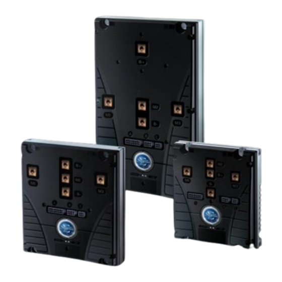
Frame Dimensions The Sigmadrive is constructed in three frame sizes – small, medium and large. This can be identified from the last character of the product code. For example, ACP425S is a Small frame size. Small Frame SK79647-02... -
Page 11: Medium Frame
PG D AC P – I RIVES ECHNOLOGY NSTALLATION Medium Frame SK79647-02... -
Page 12: Large Frame
AC P – I PG D NSTALLATION RIVES ECHNOLOGY Large Frame SK79647-02... -
Page 13: Mounting
It is suggested that the cables are mounted so that they loop up to the controller, therefore minimizing the flow of moisture into the connectors. Route wiring to keep lengths as short as possible, especially the high current motor and battery cabling. SK79647-02... -
Page 14: Wiring Guidance
AC P – I PG D NSTALLATION RIVES ECHNOLOGY Wiring Guidance SK79647-02... -
Page 15: Battery And Motor Connections
5.1.1 Tightening Torque for Battery and Motor Connections The medium and large frame sizes use M8 screws and these should be tightened to 11Nm. The small frame size uses M6 screws and these should be tightened to 9Nm. SK79647-02... -
Page 16: Battery And Motor Wire Size And Type Selection
16 way Pump Interface Connector 8 way Communications Connector 6 way Motor Feedback Connector Control Connection Wiring Use 0.5mm /20AWG wire gauge for all control connections. It is also recommended that Tri-rated wire with a 105ºC insulation rating is used. SK79647-02... -
Page 17: Control Connections Crimps And Tooling
It is the responsibility of the application’s manufacturer to ensure appropriate fuses, line contactors and emergency disconnect switches are used and that these devices are appropriately located. PGDT accepts no liability for losses of any kind if inappropriate devices or arrangements are used. SK79647-02... -
Page 18: Motor Connections
When closed, this input will activate the pump speed set by the programmable parameter, 1.6 Speed 3. Pin 4 – Pump Switch 4 Pump Switch 4 is typically used to operate an auxiliary pump function. When closed, this input will activate the pump speed set by the programmable parameter, 1.7 Speed 4. SK79647-02... -
Page 19: Pin 5 - Pump Switch 5
Accelerator 100% Voltage. The former parameter sets the voltage that relates to zero drive demand from the pump potentiometer while the latter parameter sets the voltage that relates to 100% drive demand from the potentiometer. For maximum safety, 5V to 0V voltage signals should always by connected to pin 8. SK79647-02... -
Page 20: Pin 10 - Keyswitch
A supply for the 5kΩ pump potentiometer that is the input to pin 9. Connector ‘B’ – Communications (8-way) Pin 1 – Not Used Not used. Pin 2 – Not Used Not used. Pin 3 – Flash Programming Mode (+12V) For use with the Flash Programmer. SK79647-02... -
Page 21: Pin 4 - Flash Programmer I/O
Type. Once the correct sensor type has been set, the parameter, 4.1 Motor Temperature Cutback, can then be used to set the temperature at which current foldback will begin. Pin 5 – +12V Supply A 12V supply with a maximum current of 20mA. This output can be used for the motor encoder supply. SK79647-02... -
Page 22: Pin 6 - 0V
The complete installation should be documented in detail and faithfully reproduced on all production versions. When making changes, consider their effect on compliance, ahead of other factors such as cost reduction. SK79647-02... -
Page 23: Chapter 2 - Adjustments
PG D AC P – A RIVES ECHNOLOGY DJUSTMENTS CHAPTER 2 – ADJUSTMENTS SK79647-02... - Page 24 AC P – A PG D DJUSTMENTS RIVES ECHNOLOGY SK79647-02...
-
Page 25: Adjustments
- n/a - 1.38 Not Used - n/a - 1.39 Not Used - n/a - 1.40 Not Used - n/a - 1.41 Not Used - n/a - 1.42 Not Used - n/a - 1.43 Not Used - n/a - SK79647-02... -
Page 26: Acceleration - (Accel)
Speed 3 and Speed 6. The pump motor will accelerate or decelerate to the new speed demand using the programmed Acceleration and Deceleration rates. The adjustable range is 0Hz to 255Hz in 1.0Hz steps. Speed 4 – (Pspeed4) This sets the pump speed when the switch wired to pin 4 of Connector A is active. SK79647-02... -
Page 27: Speed 5 - (Pspeed5)
Acceleration / Deceleration Speed 6 – (Paccel 6) When the power steer trigger is active, the controller uses this rate for acceleration and deceleration instead of those set by 1.1 Acceleration & 1.2 Deceleration. The adjustable range is 0.1s to 10.0s in 0.1s steps. SK79647-02... -
Page 28: Maximum Current - (Maxcurr)
This parameter is not applicable to Pump operation. 1.25 Not Used This parameter is not applicable to Pump operation. 1.26 Not Used This parameter is not applicable to Pump operation. 1.27 Not Used This parameter is not applicable to Pump operation. SK79647-02... -
Page 29: Not Used
This parameter is not applicable to Pump operation. 1.36 Not Used This parameter is not applicable to Pump operation. 1.37 Not Used This parameter is not applicable to Pump operation. 1.38 Not Used This parameter is not applicable to Pump operation. SK79647-02... -
Page 30: Not Used
This parameter is not applicable to Pump operation. 1.41 Not Used This parameter is not applicable to Pump operation. 1.42 Not Used This parameter is not applicable to Pump operation. 1.43 Not Used This parameter is not applicable to Pump operation. SK79647-02... -
Page 31: Chapter 3 - Diagnostics
PG D AC P – D RIVES ECHNOLOGY IAGNOSTICS CHAPTER 3 – DIAGNOSTICS SK79647-02... - Page 32 AC P – D PG D IAGNOSTICS RIVES ECHNOLOGY SK79647-02...
-
Page 33: Error Detection
The Programmer’s Status menu also allows both the current and previous error codes to be viewed. See section, Status, for more details. Lastly, the Sigmagauge display can signal an error, using specific icons. Refer to the Sigmagauge chapter for further details. SK79647-02... -
Page 34: Error Codes
Battery voltage too low. Charge battery or check its condition and connections. High-side MOSFET error in neutral or while pulsing. Check motor insulation and line contactor. If error persists, contact Service Agent. Low-side MOSFET error while pulsing. Check motor insulation. If error persists, contact Service Agent. SK79647-02... - Page 35 CAN error. A CAN node is not responding. Check all nodes and their connections. Over-speed or encoder error. Check encoder programming value 4.3 Number of Teeth is correct and ensure that 4.8 Motor Speed Maximum is higher than 1.4 Speed 1. SK79647-02...
-
Page 36: Status
Maximum permitted voltage for the current Stator Frequency 2.21 PGDT Use Only 2.22 PGDT Use Only 2.23 PGDT Use Only 2.24 PGDT Use Only *See section, Further Status Information. **The use of a current clamp or similar measuring device is recommended at lower levels. SK79647-02... -
Page 37: Further Status Information
AC Slip Limit, i.e. the maximum possible slip is being applied. The status information 2.12 Motor Voltage, also relays the current error code. This is in the form of an abbreviation as shown below. Fxx: Error Code, where ‘xx’ denotes the specific error. SK79647-02... -
Page 38: Test
0/1 0 = Off, 1 = On 5.22 Green LED 0/1 0 = Off, 1 = On 5.23 Contactor Driver Feedback 0/1 0 = No Contactor Driven, 1 = 1 Or More Contactors Driven 5.24 0/1 0=12V Internal Rail Low, 1= 12V OK SK79647-02... -
Page 39: Chapter 4 - Controller Set-Up
PG D AC P – C RIVES ECHNOLOGY ONTROLLER CHAPTER 4 – CONTROLLER SET-UP SK79647-02... - Page 40 AC P – C PG D ONTROLLER RIVES ECHNOLOGY SK79647-02...
-
Page 41: Controller Set-Up
Motor Temperature Sensor Type MTempTyp 3.14 Analogue Inputs Set-up Accel 8/9 3.15 Not Used - n/a - 3.16 Not Used - n/a - 3.17 CAN Node Number CAN node 3.18 Shared Line Contactor ShareLC 3.19 Last Sharing Node LstNode SK79647-02... -
Page 42: Accelerator Characteristic - (Lin/Curv)
If set to 1 (Hi), the input will be active when a switch connected to pin 7 is open. Pump Power-up – (Nchk/Chk) This sets whether or not the pump is checked at power-up. There are two programmable options – 0 and 1. SK79647-02... -
Page 43: Pot. & Switch - (Nosw/Sw)
Option 3 is not applicable to Pump operation. Option 4 is not applicable to Pump operation. If set to 5 (Motor Current), then the motor current in units of ‘A’ will be displayed, from 0 to the maximum rated current of the controller. SK79647-02... -
Page 44: Not Used
In a non-CANbus system, the controller(s) should have this parameter set to 0. This is particularly important if the BDI is used. As detailed above, the BDI will not work when set up as a slave controller. To set the CAN node number in a controller, it must be disconnected from the CANbus. SK79647-02... -
Page 45: Shared Line Contactor - (Sharelc)
For example, if there are four controllers connected and they have node numbers of 0, 1, 2 and 3, then this parameter should be set to 3. SK79647-02... - Page 46 AC P – C PG D ONTROLLER RIVES ECHNOLOGY SK79647-02...
-
Page 47: Chapter 5 - Motor Set-Up
PG D AC P – M RIVES ECHNOLOGY OTOR CHAPTER 5 – MOTOR SET-UP SK79647-02... - Page 48 AC P – M PG D OTOR RIVES ECHNOLOGY SK79647-02...
-
Page 49: Motor Set-Up
- n/a - 4.36 Current Threshold CurrTH 4.37 Lower Maximum Current ImaxLow 4.38 Threshold Timer IthTime 4.39 Not Used - n/a - 4.40 Not Used - n/a - 4.41 Not Used - n/a - 4.42 Not Used - n/a - SK79647-02... -
Page 50: Motor Temperature Cutback - (Tempstrt)
The controller then, in response to pump potentiometer position and speed feedback from the Motor Encoder, adjusts the voltage and slip values between their minimum and maximum values. The minimum voltage is 25% of the maximum motor voltage, whereas the slip has a theoretical minimum of zero. SK79647-02... -
Page 51: Motor Speed Minimum - (Spdmin)
200Hz is required, then this parameter should be set to at least 220Hz. The adjustable range is 0Hz to 255Hz in 1Hz steps. The four parameters detailed above are hierarchical – i.e. Motor Speed Base must never be set less than Motor Speed Boost or greater than Motor Speed Maximum. SK79647-02... -
Page 52: Minimum Voltage - (Vmin)
The adjustable range is 0Hz to 15.93Hz in 0.0625Hz steps. 1.17 Drive Slip Maximum – (D Smax) This sets the maximum slip that can be applied by the controller at the maximum speed setting. The adjustable range is 0Hz to 15.93Hz in 0.0625Hz steps. SK79647-02... -
Page 53: Motor Braking Set-Up Explained
The adjustable range is 0.1V to 88.5Vrms in 0.1Vrms steps. 1.21 Braking Voltage Maximum – (B Vmax) This sets the controller output voltage applied at the maximum speed setting during braking. The adjustable range is 0.1V to 88.5Vrms in 0.1Vrms steps. SK79647-02... -
Page 54: Braking Slip Minimum - (B Smin)
Proportional Gain for Voltage Change – (PgainV) This sets the PI gain factor for Voltage. The pump drives more smoothly at a lower value or more responsively at a higher value. The adjustable range is 1 to 16 in 1 step increments. SK79647-02... -
Page 55: Proportional Gain For Outer Speed Loop
‘threshold time’. If necessary, once this period has expired, the current can then be returned to its original level. 1.36 Current Threshold – (CurrTh) This sets the level of current, which if exceeded, will activate 4.38 Threshold Timer. The adjustable range is 50Arms to the maximum rating of the controller in 10Arms steps. SK79647-02... -
Page 56: Lower Maximum Current - (Imaxlow)
460Arms ACP445M 320Arms 320Arms 320Arms ACP425S 180Arms 150Arms 120Arms The values in the preceding table should never be exceeded. 1.39 Not Used Not used. 1.40 Not Used Not used. 1.41 Not Used Not used. 1.42 Not Used Not used. SK79647-02... -
Page 57: Chapter 6 - Motor Set-Up Example
PG D AC P – M RIVES ECHNOLOGY OTOR XAMPLE CHAPTER 6 – MOTOR SET-UP EXAMPLE SK79647-02... - Page 58 AC P – M PG D OTOR XAMPLE RIVES ECHNOLOGY SK79647-02...
-
Page 59: Example Set-Up Procedure
Motor Speed Maximum, set to 1.5 times Motor Speed Base value or 10% higher than the maximum motor rpm required, whichever is greater. In this example, the motor manufacturer’s data sheet indicated a maximum motor frequency of 114Hz. Therefore Motor Speed Maximum should be set to 125Hz (114+10%). SK79647-02... -
Page 60: Drive Voltage Set-Up
Slip Minimum is set to 70% of the Drive Slip Base value. The relationship between current and slip is not linear but this set-up is usually a good starting point for a safe first test. Therefore, in this example the settings would be as follows. Drive Slip Minimum: 1.57Hz Drive Slip Boost: 2.24Hz Drive Slip Base: 2.24Hz Drive Slip Maximum: 2.24Hz SK79647-02... -
Page 61: Motor Set-Up - Braking
Therefore, in this example the settings would be as follows. Braking Voltage Minimum: 1.7Vrms Braking Voltage Boost: 15Vrm Braking Voltage Base: 30Vrms Braking Voltage Maximum: 30Vrms By combining the braking values calculated so far, the following graph can be plotted. SK79647-02... -
Page 62: Fine-Tuning Drive
10Arms below the maximum allowed for the motor or the controller. Now you can increase the value of 4.14 Drive Slip Minimum. Again, ensure the measured motor current does not exceed the maximum rated value for the motor or controller. If the lift starts to lurch, the slip is too high and can be reduced. SK79647-02... -
Page 63: The Results After Fine-Tuning
Motor Speed Maximum: 125Hz Minimum Voltage: 0.6Vrms Drive Voltage Minimum: 3.8Vrms Drive Voltage Boost: 30.0Vrms Drive Voltage Base: 30.0Vrms Drive Voltage Maximum: 30.0Vrms Drive Slip Minimum: 1.50Hz Drive Slip Boost: 2.87Hz Drive Slip Base: 2.62Hz Drive Slip Maximum: 2.50Hz SK79647-02... -
Page 64: Final Checks
If any doubt exists, consult the vehicle’s operating manual for details of maximum operating conditions and to determine what constitutes safe operation in each of the scenarios above. PGDT accepts no liability for losses of any kind arising from failure to comply with this condition. SK79647-02... -
Page 65: Chapter 7 - Hand-Held Programmer
PG D AC P – H RIVES ECHNOLOGY HELD ROGRAMMER CHAPTER 7 – HAND-HELD PROGRAMMER SK79647-02... - Page 66 AC P – H PG D HELD ROGRAMMER RIVES ECHNOLOGY SK79647-02...
-
Page 67: Introduction
Programmer. For normal Sigmadrive programming and diagnostics, this switch must be set to position 2. Positions 1 and 3 are for Sigmadrive and Programmer software upgrades. Refer to the section Software Upgrades later in this manual for more details. SK79647-02... -
Page 68: Connection
This button is used to select a highlighted menu item, and to return to the main menu. This button is used to decrement the value of a highlighted parameter. This button is used to increment the value of a highlighted parameter. SK79647-02... -
Page 69: Programmer Map
This menu includes parameters specifically related to the type of motor being used. Refer to the Motor Set-up chapter for full details. 4.1.5 Test This menu allows you to select controller I/O status for display, such as the state of digital and analogue inputs, or contactor and LED outputs. Refer to the Diagnostics chapter for full details. SK79647-02... -
Page 70: 4.1.6 About
Software Upgrades The Programmer can be used to load revised software into the controller. Likewise, the Programmer’s own software can be revised. If either of these operations is required to be undertaken, PGDT will supply more detailed and specific instructions. SK79647-02... -
Page 71: Chapter 8 - Calibration
PG D AC P – C RIVES ECHNOLOGY ALIBRATION CHAPTER 8 – CALIBRATION SK79647-02... - Page 72 AC P – C PG D ALIBRATION RIVES ECHNOLOGY SK79647-02...
-
Page 73: Calibration
PGDT accepts no liability for losses of any kind arising from failure to comply with this condition. 1.2 – 1.7 Offset and Gain Settings These parameters are factory settings and should not be altered under any circumstances. SK79647-02... - Page 74 AC P – C PG D ALIBRATION RIVES ECHNOLOGY SK79647-02...
-
Page 75: Chapter 9 - Sigmagauge
PG D AC P – S RIVES ECHNOLOGY IGMAGAUGE CHAPTER 9 – SIGMAGAUGE SK79647-02... - Page 76 AC P – S PG D IGMAGAUGE RIVES ECHNOLOGY SK79647-02...
-
Page 77: Introduction
The controllers have their own separate counter. 1.1.6 Information Field A 2x9 character field to show customized text, e.g. vehicle OEM and type. The membrane buttons can be used in the Gauge Set-up menu to edit the text displayed. SK79647-02... -
Page 78: Connection
Before cutting the hole, ensure that enough room is available within the dash for the area of the module and the Securing Bracket. Access to the back of the dash will be required to secure the Sigmagauge. SK79647-02... -
Page 79: Configuring The Sigmagauge
3. Reset all pincodes Reset all pin codes Contact PGDT About SW version and date Indication of the software Indication only version and date Return Select to return to main Select with up & down arrows menu and confirm with ‘SEL’ SK79647-02... - Page 80 AC P – S PG D IGMAGAUGE RIVES ECHNOLOGY SK79647-02...
-
Page 81: Chapter 10 - Technical Specifications
PG D AC P – T RIVES ECHNOLOGY ECHNICAL PECIFICATIONS CHAPTER 10 – TECHNICAL SPECIFICATIONS SK79647-02... - Page 82 AC P – T PG D ECHNICAL PECIFICATIONS RIVES ECHNOLOGY SK79647-02...
-
Page 83: Electrical
The enclosure is protected to IP54 (varnished PCB). Vibration: 6G, 40-200Hz for 1 hour, in x, y and z planes. -30 o C to +40 o C ambient around controller. Operating Temperature: -40 o C to +70 o C. Storage Temperature: Humidity: 95% maximum, non-condensing. SK79647-02... -
Page 84: Mechanical
Small: 1.2Kg; Medium: 4.1Kg; Large: 6.1Kg. Always use a torque screwdriver when fixing the power terminals. Exceeding the maximum specified torque can cause serious damage to the controller and warranty may be void. Screws that are too long will damage the controller. SK79647-02...
Need help?
Do you have a question about the SK79647-02 and is the answer not in the manual?
Questions and answers