Table of Contents
Advertisement
Quick Links
Advertisement
Table of Contents

Related Manuals for Circutor SVG


Summary of Contents for Circutor SVG
- Page 1 Static var generator INSTRUCTION MANUAL (M190B01-03-18A)
- Page 2 Instruction Manual...
-
Page 3: Safety Precautions
DISCLAIMER CIRCUTOR, SA reserves the right to make modifi cations to the device or the unit specifi ca- tions set out in this instruction manual without prior notice. CIRCUTOR, SA on its web site, supplies its customers with the latest versions of the device specifi cations and the most updated manuals. www.circutor.com CIRCUTOR, recommends using the original cables and accessories that are supplied with the device. -
Page 4: Table Of Contents
3�6�1�- 30 kvar SVG: SVG-3Wx-30k ������������������������������������������������������������������������������������������������������������20 3�6�2�- 100 kvar SVG RACK-TYPE : SVG-3Wx-100kR �������������������������������������������������������������������������������22 3�6�3�- 100 kvar AND 200 kvar SVG CABINET-TYPE : SVG-3WF-100k and SVG-3WF-200k �����������������23 3�7�- CONNECTION DIAGRAMS ��������������������������������������������������������������������������������������������������������������������27 3�7�1�- 3-WIRE CONNECTION AND CURRENT MEASUREMENT ON THE MAIN SIDE� ��������������������������27 3�7�2�- 3-WIRE CONNECTION AND CURRENT MEASUREMENT ON THE LOAD SIDE�... - Page 5 10�2�1�- 30 kvar SVG : SVG-3Wx-30k ��������������������������������������������������������������������������������������������������������� 70 10�2�2�- 100 kvar SVG RACK-TYPE: SVG-3Wx-100kR ����������������������������������������������������������������������������� 72 10�2�3�- 100 kvar AND 200 kvar SVG cabinet-type : SVG-3WF-100k AND SVG-3WF-200k �������������������� 75 10�3�- FUSES ( Models SVG-3WF-100k and SVG-3WF-200k) ���������������������������������������������������������������������� 75 11�- TECHNICAL FEATURES ������������������������������������������������������������������������������������������������������������������������������� 76 12�- TECHNICAL SERVICE ����������������������������������������������������������������������������������������������������������������������������������...
-
Page 6: Revision Log
REVISION LOG Table 1: Revision log� Date Revision Description 12/17 M190B01-03-17A Initial Version Changes in sections: 02/18 M190B01-03-18A 1.1.- 1.2. - 2. - 3.2.1.2. - 3.2.1.3. - 3.4.2. - 3.4.3. - 3.5. - 3.6. - 3.8.2. - 4.2. - 5. - 6.1. - 7.5. - 9.2. - 10.2. - 10.3. - 11. SYMBOLS Table 2: Symbols�... -
Page 7: 1�- Verification Upon Reception
Check that it has been delivered with the following: - Instruction manual - Communication cable for connecting devices in parallel. - Trim panel (Cabinet-type SVG : SVG-3WF-100k and SVG-3WF-200k). - Bag with 5 rubber caps (SVG-3WF-30k). e) Perform an external and internal visual inspection of the device prior to connecting it. - Page 8 When unpacking the device, pay attention to prevent damaging the device if you are using cut- ting tools, such as cutters, scissors or knives. SVG 100 kvar (SVG-3WF-100k) and 200 kvar (SVG-3WF-200k) cabinets are delivered with the base removed to enable them to be transported with a pallet jack or similar.
-
Page 9: 1�3�- Storage
1.3.- STORAGE The device should be stored according to the following recommendations: Avoid placing them on uneven surfaces. Do not store them in outdoor areas, humid areas or areas exposed to splashing wa- ter. Avoid hot spots (maximum ambient temperature: 50ºC) Avoid salty and corrosive environments. -
Page 10: 2�- Product Description
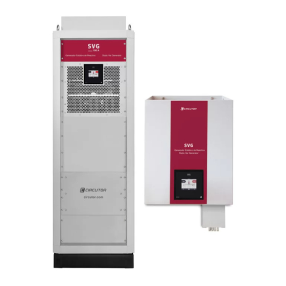
2�- PRODUCT DESCRIPTION The SVG static var generator can be used to correct the power factor. For both backward (in- ductive) and forward (capacitive) currents. There are different models of the device, for different currents: SVG 30 kvar, The device features: - 3-wire multifunction, for installation in three-phase mains (3 or 4 wires) up to 480 V~ - Parallel installation of up to 100 devices. - Page 11 There are three types of 100 kvar devices: - Rack-type master devices, with all of the features (SVG-3WM-100kR) - Rack-type slave devices, designed to operate as slaves in parallel multi-function SVG connections (SVG-3WS-100kR) - Cabinet-type devices, with all of the features (SVG-3WF-100k)
- Page 12 SVG 200 kvar, The 200 kvar model (SVG-3WF-200k) is a cabinet-type model with two 100 kvar devices con- nected in parallel. The device features: - 3-wire multifunction, for installation in three-phase mains (3 or 4 wires) up to 480 V~ - Parallel installation of up to 100 devices..
-
Page 13: 3�- Device Installation
Disconnect the main switch before starting any maintenance task on the SVG� Make sure the device is properly earthed before powering up. Any fault in the earth connection might cause a risk of electrocution to the user and damage to the device itself in the case of lightning or other transients. -
Page 14: 3�2�- Installation Location
To maintain the device’s performance, we recommend ensuring that the air circulates freely through the front panel of the SVG-3Wx-100kR, and that the rear is free of obstacles, with a gap of at least 300 mm. - Page 15 With deflectors installed. 3�2�1�3�- SVG cabinet-type: SVG-3WF-100k and SVG-3WF-200k The cabinet-type SVG uses a forced ventilation cooling system, with an air inlet on the front panel and an air outlet at the back of the device. The ventilation grille at the top must not be blocked, leaving enough space to the ceiling to allow the heat to dissipate.
-
Page 16: 3�3�- Storage For Long Periods
STOP mode 3.4.- INSTALLATION 3�4�1�- 30 kvar SVG: SVG-3Wx-30k The SVG of 30 kvar has a number of holes on the top and bottom of the device, Figure 4, facilitate transport and installation of the device. These holes can be used as attachment points for external manipulation tools, or a bar (not included) can be passed through them to improve transport and installation of the device. -
Page 17: 3�4�2�- 100 Kvar Svg Rack-Type: Svg-3Wx-100Kr
2�- Open or remove the door at the front of the cabinet. 3�- Place the SVG on the cabinet’s rails or shelves. Make sure that they are suitable for the weight of the device; use cross braces if necessary. -
Page 18: 3�4�3�- 100 Kvar And 200 Kvar Svg Cabinet-Type: Svg-3Wf-100K And Svg-3Wf-200K
3�4�3�- 100 kvar AND 200 kvar SVG CABINET-TYPE: SVG-3WF-100k AND SVG-3WF-200k The 100 kvar (SVG-3WF-100k) and 200 kvar (SVG-3WF-200k) models of the SVG are free-standing cabinets with 4 bearing supports on the floor. The mounting surface must be solid, support the device’s weight and be level. The cabinet must never be welded to the floor using arc welding, as this may destroy the electronic components. -
Page 19: 3�5�- Connection
3.5.- CONNECTION SVG-3Wx-30k and SVG-3Wx-100kR models: Use cables of a cross-section suitable for the nominal current of the SVG and that comply with the standards of the country in which they are being installed. The earth conductor must have at least the same cross-section as the phase conductors. -
Page 20: 3�6�- Device Terminals
3.6.- DEVICE TERMINALS 3�6�1�- 30 kvar SVG: SVG-3Wx-30k The connection terminals of the SVG-3Wx-30k model are located on the lower face of the de- vice. The SVG model without an EMI filter (SVG-3WS-30k) has a terminal cover on the main connection terminals. - Page 21 6: S, RS-485 communications 14: L2, Main connection L2 7: S1, Current input L1 15: L3, Main connection L3 8: S2, Current input L1 16: Earth connection 9 10 11 12 4 5 6 Figure 9:SVG terminals without EMI filter (SVG-3WS-30k). Instruction Manual...
-
Page 22: 3�6�2�- 100 Kvar Svg Rack-Type : Svg-3Wx-100Kr
4 5 6 Figure 10:SVG terminals with EMI filter (SVG-3WF-30k). 7 8 9 10 11 12 Note : SVG-3WF-30k device includes rubber caps to cover grid terminal screws, if required by installation environment 4 5 6 It is recommended to fix the connection cables to the holes that facilitate the... -
Page 23: 3�6�3�- 100 Kvar And 200 Kvar Svg Cabinet-Type : Svg-3Wf-100K And Svg-3Wf-200K
3�6�3�- 100 kvar AND 200 kvar SVG CABINET-TYPE : SVG-3WF-100k and SVG-3WF-200k There are sliding windows at the bottom of the cabinet so that the connection wiring can be slotted inside, . These windows can be removed and machined if it is considered nec- Figure 13 essary to use a cable gland. - Page 24 SVG-3WF-100k 1 2 3 4 5 6 Floor Figure 15: SVG-3WF-100k terminals part 1� Note: The dimensions of are in mm. Figure 15 SVG-3WF-200k 1 2 3 4 5 6 Floor Figure 16: SVG-3WF-200k terminals part 1� Note: The dimensions of are in mm.
- Page 25 6: S, 4 5 6 Figure 17: SVG terminals part 2 (SVG-3WF-100k and SVG-3WF-200k)� The connection cables should be passed through the cable grommet at the bottom of the cabinet. We recommend separating the communications cables from the power cables, to reduce interference.
- Page 26 Cables Figure 18: Running the cables along the side of the cabinet� When the wiring is complete, fit the cover at the back and the front covers (torque 5 Nm) Instruction Manual...
-
Page 27: 3�7�- Connection Diagrams
3.7.- CONNECTION DIAGRAMS 3�7�1�- 3-WIRE CONNECTION AND CURRENT MEASUREMENT ON THE MAIN SIDE� P2 P1 S1 S2 S1 S2 S1 S2 MCCB CARGA / LOAD RED/ MAINS P2 S1 Figure 19: Three-phase measuring with 3-wire connection and current measurement on the main side� Instruction Manual... -
Page 28: 3�7�2�- 3-Wire Connection And Current Measurement On The Load Side
3�7�2�- 3-WIRE CONNECTION AND CURRENT MEASUREMENT ON THE LOAD SIDE� P2 P1 S1 S2 S1 S2 S1 S2 MCCB CARGA / LOAD RED/ MAINS P2 S1 Figure 20: Three-phase measuring with 3-wire connection and current measurement on the load side� Instruction Manual... -
Page 29: 3�7�3�- 3-Wire Connection And 2 Current Transformers On The Main Side
3�7�3�- 3-WIRE CONNECTION AND 2 CURRENT TRANSFORMERS ON THE MAIN SIDE� P2 P1 S1 S2 S1 S2 S1 S2 MCCB CARGA / LOAD RED/ MAINS Figure 21: Three-phase measuring with a 3-wire connection and 2 current transformers on the main side� The connection of 2 current transformers is only possible in three-phase mains without neutral (3 wires). -
Page 30: 3�7�4�- 3-Wire Connection And 2 Current Transformers On The Load Side
3�7�4�- 3-WIRE CONNECTION AND 2 CURRENT TRANSFORMERS ON THE LOAD SIDE� P2 P1 S1 S2 S1 S2 S1 S2 MCCB CARGA / LOAD RED/ MAINS Figure 22: Three-phase measuring with a 3-wire connection and 2 current transformers on the load side� The connection of 2 current transformers is only possible in three-phase mains without neutral (3 wires). -
Page 31: 3�8�- Parallel Connection Of 2 To 100 Devices
3.8.- PARALLEL CONNECTION OF 2 TO 100 DEVICES The SVG devices can be arranged in parallel. Up to 100 devices can be arranged in parallel, either of the 30 kvar or 100 kvar models. In the case of installations with devices in parallel, a device must be defined as the “master”, while all others will have “slave” devices functions. The “master” will be responsible for measuring the network parameters, so only the current transformers will be connected to it. -
Page 32: 3�8�1�- Connecting Individual Devices
3�8�1�- CONNECTING INDIVIDUAL DEVICES Note: CIRCUTOR has devices that are factory-configured as slaves to enable devices to be connected in parallel. To connect multiple individual devices in parallel, follow these steps: 1�- Select the device that will operate as the “master”. Note: Devices that are factory-configured as “slaves” cannot perform this function. -
Page 33: 3�8�2�- Connecting Cabinets
3�8�2�- CONNECTING CABINETS Note: The 200 kvar (SVG-3WF-200k) devices are composed of 2 100 kvar devices in parallel. They are connected and configured in parallel in the factory. To connect multiple cabinets in parallel, follow these steps: 1�- Select the cabinet that is to contain the “master”... - Page 34 Slave Master (*) Connections already included in the cabinets SVG-3WF-100k Figure 26:Connecting 3 devices in parallel, using the communication cable (100 kvar master SVG)� Connect them using the communication cables ( Table 16 Table 16: Communication cable, devices in parallel�...
- Page 35 Connect them using the communication cables supplied ( Table 16 Note: The communication cable must be a CAT 5 cable. Maximum cable length 3 metres. 5�- Configure the installation in the “master” device (see “7.- CONFIGURATION” On the Installed devices ( ) screen you need to enter the number “7.5.- INSTALLED DEVICES”...
-
Page 36: 4�- Operation
Actively, by generating a current with the same magnitude as the active current to compensate, in the opposite phase. The SVG is a device included in the second group. It uses the current measured with external current transformers to generate a counter-phase current, with the magnitude required to ob- tain the cos Φ... -
Page 37: 4�2�- Display
ductive currents. In addition, its operation does not depend on the content of harmonics in the network, so it can be used in distorted networks, with no need to add filtering elements to the installation. 4.2.- DISPLAY The device features a 3.5” TFT display on the front part in order to be able to view and configure all of the parameters of the device. Figure 30: Display� The display enters the energy saving mode 10 minutes after the last action. To reactivate it, just touch the display. -
Page 38: 4�2�2�- Central Area
4�2�2�- CENTRAL AREA Figure 32: Central area� This area shows: The condition of the installation, All parameters and graphs of the device. symbol, when a warning has been generated. See section “ ” The 6.8.- WARNINGS And the necessary keys at each point, Table 17 Table 17: Central area keys� Function Restarts the device after an alarm. -
Page 39: 5�- Start
4�- Go back to the home screen of the device, , if there is no problem with the connec- Figure 34 tions, the upper area should show the message “Stop”. If there is a problem with the device connections or the configuration, the “Waiting for condi- tions” message appears. 5�- Press the key to start the SVG. If it has started correctly, the screen will show the message “Run”. Instruction Manual... -
Page 40: 6�- Display
STOP key is the start and stop key of the SVG. Use the keys to navigate through the different display screens. In the upper part of the screen, a message with the current status of the device is shown (... -
Page 41: 6�2�- Voltage, Current And Frequency
Table 19 (Cont�) : Status messages Status messages Description Configuring the device. Description Device is operating. Sync Description The SVG is synchronising with the main. Charging Bus DC Description Charging process of the internal bus prior to start-up. Stop Description Device stopped. Alarm An alarm has been generated. -
Page 42: 6.3.- Power And Cos ɸ Of Mains
6.3.- POWER AND COS ɸ OF MAINS shows the power and cos ɸ of the main. Figure 37 Figure 37: Display of the power and cos ɸ of the main. It shows: The Active Power, P. The Reactive Power, Q. The Apparent Power, S. The cos ɸ Note: The - sign in reactive power indicates that it is capacitive and the + sign that it is inductive. Note: If a system has been configured with devices in parallel, the values displayed for the device configured as the “master”... -
Page 43: 6.4.- Power And Cos ɸ Of Load
6.4.- POWER AND COS ɸ OF LOAD shows the power and cos ɸ of the load. Figure 38 Figure 38: Display of the power and cos ɸ of the load. It shows: The Active Power, P. The Reactive Power, Q. The Apparent Power, S. The cos ɸ. Note: The - sign in reactive power indicates that it is capacitive and the + sign that it is inductive. Note: If a system has been configured with devices in parallel, the values displayed for the device configured as the “master”... -
Page 44: 6�5�- Mains Phasors
6.5.- MAINS PHASORS In this screen, , the main phasors are shown. Figure 39 Figure 39: Main phasors� Use the keys to navigate through the different display screens. 6.6.- LOAD PHASORS In this screen, , the load phasors are shown. Figure 40 Figure 40: Load phasors�... -
Page 45: 6�7�- Alarms
Table 20:Alarm messages� Alarm messages Overcurrent L1/L2/L3 Description The SVG current is too high. Corrective This alarm may be associated with transients and noise in the power supply voltage. Check the action quality of the power supply voltage. If it continues, contact the Technical Assistance Service... -
Page 46: 6�8�- Warnings
On pressing the key; if there are active warnings, the screen shown in Figure 42 will be displayed and the user will be asked for confirmation to continue with the SVG start-up process. Figure 42: Confirm screen. This screen, , shows the active warnings. shows the warnings that can ap-... - Page 47 Figure 43: Warnings� Use the keys to navigate through the different display screens. Table 21: Warnings messages� Warnings messages Waiting for conditions Description The start-up conditions are not met. Corrective Check the alert messages. action Load polarity Description Detection of an error in the load polarity. Corrective Check the transformer connections.
- Page 48 Main current below the programmed level. Corrective Check the configuration. action Maximum load Description SVG working at full load Corrective No action is necessary. action Low power factor The power factor value measured is less than 0.7, which might indicate a connection error...
-
Page 49: 6�9�- Temperature
Figure 44 Figure 44: Temperature� Note: The temperature of the inductors and IGBTs can be high. The SVG is protected from these temperatures and they do not present any risk for the device. Note: If a system has been configured with devices in parallel,the “master” device’s temperature values are displayed on the “master”... -
Page 50: 6�11�- Device Information
6.11.- DEVICE INFORMATION In this screen, , the serial number, HMI and DSP versions of the device are shown. Figure 46 Figure 46: Device information� The touch panel of the display is calibrated from factory, but depending on the installation con- ditions, it may be necessary to recalibrate it. -
Page 51: 6�12�- Slave Device Status
6.12.- SLAVE DEVICE STATUS Note: This screen is only displayed if a system has been configured with devices in parallel and the device has been configured as the “master”. This screen, shows the status of each “slave” device. Figure 48, Figure 48: Slave device status screen (1)� The “slave”... -
Page 52: 7�- Configuration
7�- CONFIGURATION shows the main configuration screen. Figure 50 Figure 50: Main configuration screen. By pressing the key, the setup menu is accessed in display mode, i.e., all param- eters of the device are shown but they cannot be modified. By pressing the key, the setup menu is accessed in edit mode, i.e., the parame- ters of the device can be modified. In this case, before entering the setup menu it is necessary to enter the password, Figure 51... -
Page 53: 7�1�- Language
7.1.- LANGUAGE Note: This screen does not have to be configured if the device is going to operate as a slave. In this screen, , the language of the display is selected. Figure 52 Figure 52: Configuration screen: Language. ● Language, display language, the options are: ... -
Page 54: 7�3�- Operating Limits
Note: This screen does not have to be configured if the device is going to operate as a slave. In this screen, , the operating limits of the device are configured: Figure 54 Figure 54: Configuration screen: Operating limits. ● Min current The minimum load current to start the device is configured with this parameter. The SVG will stop when the load current is below the entered value and will start when it is higher. Instruction Manual... -
Page 55: 7�4�- Transformer Configuration
Range of values: Minimum value: 0 A Maximum value: 5000 A ● Current limit This parameter allows the maximum power of the SVG to be limited. The value is configured as a percentage with respect to the device's nominal power. Range of values: Minimum value: 20% Maximum value: 100% ●... - Page 56 Range of values: Minimum value: 5 A Maximum value: 5000 A ● Invert If you activate the Invert option, the SVG changes the direction of the current of the load meas- uring transformers, with the purpose of solving installation errors. Press the key to access the next configuration step...
-
Page 57: 7�5�- Installed Devices
● Type of device: Master / Single / Slave The type of device is the first parameter that must be selected, with the following possible op- tions: Single: select this option if the SVG does not have devices connected in parallel. Master: select this option if the SVG is going to be used as the “master” of a group of devices in parallel. -
Page 58: 7�6�- Communications
Range of values: Minimum value: 0 Maximum value: 100 Press the key to access the next configuration step Press the key to access the main screen of the device without saving the configuration values. 7.6.- COMMUNICATIONS Note: This screen does not have to be configured if the device is going to operate as a slave. The communication parameters are configured in this screen, Figure 57 Figure 57: Configuration screen: Communications. -
Page 59: 7�7�- Rs-485 Communications
7.7.- RS-485 COMMUNICATIONS The RS-485 communication parameters are configured in this screen, Figure 58 Figure 58: Configuration screen: RS-485 communications. ● Modbus device, modbus address. Press the key to access the next configuration step Press the key to access the main screen of the device without saving the configuration values. 7.8.- DATE / TIME Note: This screen does not have to be configured if the device is going to operate as a slave. The time parameters are configured in this screen, Figure 59 Figure 59: Configuration screen: Date / Time... -
Page 60: 7�9�- Save Data
By activating the Internet time option, the device synchronises with the time of the Web server to which it is connected. Press the key to access the next configuration step Press the key to access the main screen of the device without saving the configuration values. 7.9.- SAVE DATA The modified configuration values are saved in the final setup menu screen, Figure 60 Figure 60: Final setup menu screen� Press the key to save the modified data. -
Page 61: 8�- Rs-485 Communications
8�- RS-485 COMMUNICATIONS SVG devices have an RS-485 serial communication output with the MODBUS RTU ® commu- nications protocol. For an installation with devices in parallel, the RS-485 connection can be made on any device. 8.1.- CONNECTIONS The RS-485 cable must be wired with twisted pair cable with mesh shield (minimum 3 wires), with a maximum distance between the SVG and the master device of 1200 metres�... -
Page 62: 8�2�1�- Example Of Modbus Query
8�2�1�- EXAMPLE OF MODBUS QUERY Query: Value of the Load current of L1 Initial No� of Address Function register registers 0001 xxxx Address: 0A, Peripheral number: 10 in decimal. Function: 03, Read function. Initial Register: C8, register from which to start reading. No�... - Page 63 8�2�2�3�- Other parameters of the SVG Table 24:Modbus memory map: SVG parameters (Table 1)� Parameter Address Units Inductor Temperature ºC with 1 decimal Temperature of IGBTs ºC with 1 decimal Phase L1 - L2 voltage V with 1 decimal Phase L2 - L3 voltage...
- Page 64 Inductor temperature alarm 0x00080000 DC bus load error 0x00100000 Contactor faults 0x00200000 NTC 3 probe temperature alarm Table 29:Modbus memory map: SVG messages (Table 3)� Parameter Address Initial Conditions for which the device does not start up. Description 0x0001 Discharging DC bus...
-
Page 65: 9�- Ethernet Communications
For an installation with devices in parallel, the Ethernet connection can be made on any device. 9.1.- CONNECTION The SVG has an ethernet port. This type of communication creates an intranet with IP communications. If the device that connects to this port is a computer, the network cable must be a crossover... - Page 66 To modify the Configuration parameters, it is necessary to enter the User and Password in the Administrator section. There are two types of user: 1�- User with write access, admin: Table 31: Default username and password for a user with write access� Default User and Password User name admin...
-
Page 67: 10�- Maintenance
10�- MAINTENANCE The SVG requires minimum preventive maintenance. It is recommended to follow the notes described in this chapter to avoid prema- ture damage to the device's components. shows the maintenance jobs with their respective time intervals. Table 33 Table 33: SVG maintenance�... - Page 68 The points to be inspected are: 1�- Set the SVG in STOP mode and open the main switch (OFF position). 2�- Wait 1 minute for the capacitors to discharge. 3�- Clean the ventilation grilles, removing the dust. 4�- If there is a lot of dirt, remove the upper and lower fan covers and clean, removing the dust from the fans and the heatsink.
-
Page 69: 10�2�- Cooling Fans
The set of fans must be replaced if they have exceeded their useful life or show signs of dete- rioration. In such cases, Circutor will provide a spare part that consists of a set of fans so that the device can be repaired quickly and easily. -
Page 70: 10�2�1�- 30 Kvar Svg : Svg-3Wx-30K
10�2�1�- 30 kvar SVG : SVG-3Wx-30k To change the fan set: Figure 66: Location of the cooling fans� 1�- Put the SVG in STOP mode and open the main switch (OFF position). 2�- Wait 1 minute for the capacitors to discharge 3�- Loosen the 6 fixing screws of the fan grille (Phillips screwdriver). - Page 71 6 screws. Note: recommended torque: 1�5 Nm 6�- Power up and start the SVG. Check the correct operation of the fans. 7�- Check the correct operation of the fans. To do so, access the maintenance screen through the setup screen by pressing the key and entering the password used to access the maintenance screen (Maintenance pass- word: 8888).
-
Page 72: 10�2�2�- 100 Kvar Svg Rack-Type: Svg-3Wx-100Kr
8�- Reset the maintenance meter of the fans by pressing the key. 10�2�2�- 100 kvar SVG RACK-TYPE: SVG-3Wx-100kR To replace the fan assembly: 1�- Put the SVG in STOP mode and open the main switch (OFF position). 2�- Wait 1 minute for the capacitors to discharge 3�- Loosen the 6 fixing screws in the upper cover and remove the cover, Figure 70 Note: Torx 25 screws Figure 70: Loosen the 6 fixing screws and remove the back cover. - Page 73 Guide with display Fans cables Figure 71: Position of the guide with the cables from the screen and fans� 5�- Loosen the 2 fixing screws in the ventilation nozzle and remove the nozzle, Figure 72 Note: 8 mm hex screws Figure 72: Remove the ventilation nozzle� 6�- Loosen the fan’s 2 fixing screws (3 mm allen screws) and tilt it forwards to remove the fan, gently pull the cable away from the fan Figure 73 Figure 73: Remove the fan�...
- Page 74 Connect the fans’ cables to the connector. 9�- Install the device’s upper cover by tightening the 6 fixing screws. Note: Recommended tightening torque: 1�5 Nm 10�- Re-connect to the electrical network and start up the SVG. 11�- Check that the fans are working properly. To do this, go to the maintenance screen, via the configuration screen, by pressing the key and entering the password to log into the maintenance screen (Maintenance password : 8888).
-
Page 75: 10�2�3�- 100 Kvar And 200 Kvar Svg Cabinet-Type : Svg-3Wf-100K And Svg-3Wf-200K
10�2�3�- 100 kvar AND 200 kvar SVG cabinet-type : SVG-3WF-100k AND SVG-3WF-200k To replace the fan assembly: 1�- Put the SVG in STOP mode and open the main switch (OFF position). 2�- Wait 1 minute for the capacitors to discharge 3�- Access the 100 kvar modules via the front panel. -
Page 76: 11�- Technical Features
0.7 inductive ... 1 ... 0.7 capacitive Up to 100 devices of different calibres Parallel connection Connection of the transformers only in the Master device Protective component against short circuits (SVG-3WF-100k and SVG-3WF-200k) Fuse NH00 160A gG 120kA 500Vac I2t 265kA2/s RS-485 Communications... - Page 77 Relative humidity (with no condensation) 0 ... 95% Maximum altitude 2,000 m Protection degree IP20 Overvoltage category OVC III 300V SVG-3WF-100k and SVG-3WF-200k Pollution degree Impact resistance IK 10 Electromagnetic compatibility Installation in type-A environments Standards Electromagnetic compatibility (CEM)� Part 6-4: Generic standards� Emis- UNE-EN 61000-6-4:2007 sions standard for industrial environments�...
- Page 78 2.2 ... 2.4 Nm Connections Type Current 6-pole connector 2.5 mm 0.5 ... 0.6 Nm Flat 3 mm RS-485 3-pole connector 2.5 mm 0.5 ... 0.6 Nm Flat 3 mm Ethernet RJ-45 SVG-3WS-30k without EMI filters. Figure 76: Dimensions : Instruction Manual...
- Page 79 1.5 ... 1.8 Nm Current 6-pole connector 2.5 mm 0.5 ... 0.6 Nm Flat 3 mm RS-485 3-pole connector 2.5 mm 0.5 ... 0.6 Nm Flat 3 mm Ethernet RJ-45 SVG-3WF-30k with EMI filters. Figure 77: Dimensions : Instruction Manual...
- Page 80 Mechanical features: SVG-3Wx-100kR Dimensions (mm) Figure 78 Weight 70 kg Enclosure Galvanised steel 1.5 mm Noise < 65 dBA Connections Type Main M8 ring terminal 23 mm 8 ... 10 Nm Earth M6 ring terminal 10 ... 14 Nm Hex 17 mm...
- Page 81 Terminal strip with Main 35 mm 6 Nm Allen 6 mm cover Current 6-pole connector 2.5 mm < 0.8 Nm Flat RS-485 3-pole connector 2.5 mm 0.5 ... 0.6 Nm Flat 3 mm Ethernet RJ-45 Figure 79: Dimensions: SVG-3WF-100k� Instruction Manual...
- Page 82 Mechanical features: SVG-3WF-200k Dimensions (mm) Figure 80 Weight 276 kg Enclosure Free-standing sheet steel cabinet, for installation indoors, without removable parts. Noise < 65 dBA Connections Type Earth Ring terminal 12 mm 35 Nm Hex 13 mm Connections Type Terminal strip with...
-
Page 83: 12�- Technical Service
• CIRCUTOR accepts no liability due to the possible damage to the unit or other parts of the installation, nor will it cover any possible sanctions derived from a pos- sible failure, improper installation or “improper usage” of the unit. Consequently,... -
Page 84: 14�- Ce Certificate
14�- CE CERTIFICATE Instruction Manual... - Page 85 Instruction Manual...
- Page 86 Instruction Manual...
- Page 87 Instruction Manual...
- Page 88 CIRCUTOR, SA Vial Sant Jordi, s/n 08232 - Viladecavalls (Barcelona) Tel: (+34) 93 745 29 00 - Fax: (+34) 93 745 29 14 www.circutor.com central@circutor.com...
Need help?
Do you have a question about the SVG and is the answer not in the manual?
Questions and answers