
Related Manuals for Cold Jet AERO2 PLT60


Summary of Contents for Cold Jet AERO2 PLT60
- Page 1 Operator Manual Original Instructions [English] 2023-03-08 Click to go to Top of Document...
-
Page 2: Table Of Contents
Cold Jet and the client and remains the exclusive property of Cold Jet. If you find any problems in the documentation, please report them to us in writing. Cold Jet does not warrant that this document is error-free. - Page 3 The Compressed Air Supply ___________________________________________________________________________ 35 Starting the Machine __________________________________________________________________________________ 39 Shutting Down the Machine __________________________________________________________________________ 42 Additional Features ___________________________________________________________________________________ 44 Advanced Settings _____________________________________________________________________________________ 49 Cold Jet CONNECT® ___________________________________________________________________________________ 54 Maintenance ___________________________________________________________________________________________ 56 Troubleshooting _______________________________________________________________________________________ 57 Warranty Policy ________________________________________________________________________________________ 58 Technical Schematics __________________________________________________________________________________ 61...
-
Page 4: System Identification
System Identification Locate the data plate for this machine and record the information provided in the spaces below. To view documentation for your machine, scan the QR code: QR code ASSEMBLY No. SERIAL No. ELECTRICAL No. AC VOLTS PHASE FREQUENCY AMPS MAX OPERATION PRESSURE MOTOR KW... -
Page 5: Introduction
Supplier Responsible for the Cold Jet, LLC Phone: 1-800-777-9101 Equipment: 455 Wards Corner Road Website: www.coldjet.com Loveland, Ohio 45140 USA Introduction About This Manual This manual should be kept with the machine and be readily accessible to machine operators and •... -
Page 6: Safety
Safety General Safety Guidelines This machine is designed to comply with international design standards and the European • Machinery Directives. Using the machine does not pose a risk to the operator when the instructions in this manual are • followed. However, certain precautions must be followed during its use. To understand all the necessary precautions, the machine operator must read the entire manual before operating or performing maintenance on the machine. -
Page 7: Electrostatic Discharge
Replace any safety labels or warning signs if they become damaged, missing, or illegible. Contact Cold Jet’s customer service department to obtain replacement labels. 2023-03-08 Click to go to Top of Document... - Page 8 Symbol Definition Attention Cold Temperature Warning Pressurized Material Ejection Hazards Electrical Hazard Asphyxiation Warning Wear protective gloves Wear hearing protection Wear eye protection Read operator manual Do not operate without safety grate in place No foreign objects allowed inside machine is in use Protective Earth/Ground Frame/Chassis Ground Terminal...
-
Page 9: Cautions And Warnings
WARNING This machine has been designed for use with 3mm dry ice pellets recommended by Cold Jet. The use of other cleaning agents or chemicals may adversely affect the safety of the machine. WARNING High pressure blast streams can be dangerous if subject to misuse. - Page 10 High pressure hoses, fittings, and couplings are important for the safety of the machine. Use only hoses, fittings, and couplings supplied by Cold Jet. WARNING To ensure machine safety, use only original and replacement parts from Cold Jet. WARNING The applicator and applicator hose contain electrical connections. Do not immerse in water.
-
Page 11: Safety Label Locations
Safety Label Locations 2023-03-08 Click to go to Top of Document... -
Page 12: Steps For Conducting A Lockout Tagout Or "Lo/To
Steps for conducting a Lockout Tagout or “LO/TO” Throughout this manual, “Lockout Tagout” (LO/TO) will be referred to in instances when power • must be removed from the machine. There are (6) universally accepted basics to this procedure. They are listed below but may not be •... -
Page 13: Emergency Stop
Emergency Stop CAUTION - Do not use the emergency stop button to shut down the machine for anything other than an emergency. The Emergency Stop button is used if the machine must be shut down immediately. • If any event occurs that could cause harm to personnel or equipment, then use the Emergency •... - Page 14 Maximum Acoustic Emissions 2023-03-08 Click to go to Top of Document...
-
Page 15: System Description
System Description The standard machine package will be supplied with the performance kit. This kit includes: 3/4 in or 1 in Performance Applicator • Performance nozzle • Nozzle handle • 1 in air supply hose 25 ft (7.62 meters) • 3/4 in or 1 in Hybrid-Flex blast hose 20 ft (6.09 meters) •... -
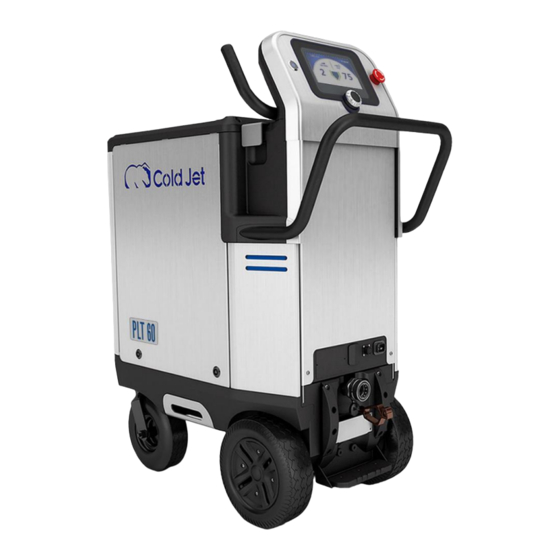
Page 16: Machine Components
Control/Display 7 in (17.7 cm) LCD screen with rotary encoder dial Communication IoT connectivity via a cellular service and Cold Jet CONNECT® capability Integration (Optional) Automation/Integration capable with PLC controlled system (integration upgrade is optional) Noise Level Noise level 60 dB(A) up to 137 dB(A) Compliance •... - Page 17 Hose Whip Check Air Supply Connection Typical Machine Setup Applicator Control Cable Air Supply Hose Nozzle Blast Hose Assembly Power Cord 2023-03-08 Click to go to Top of Document...
-
Page 18: Applicators
Applicators Performance Applicator Components 2023-03-08 Click to go to Top of Document... -
Page 19: Performance Applicator Nozzles
Specialty nozzles are also available. Contact Cold Jet's customer service department to determine the nozzle that may be most effective for your application. The tables below can be used to help with initial settings as you set up the machine for •... - Page 20 Low and Standard Flow Nozzles These straight nozzles have standard air consumption rate of 100 cfm or less at 80 psi. Nozzle Part # Blast Feed Length Material Comfort Consumption Swath rate Handle Part # 106S.6 5E0421 50cfm @ 80psi 0.6 in 1-3 lbs/min 6 in...
- Page 21 Specialty Nozzles These nozzles have various configurations for special applications and operation. Nozzle & Part # Air Consumption Blast Swath Feed rate Length Material Angle Swath Orientation Polymer 112HK 70cfm @ 80psi 0.25 in 1-3 lbs/min 12 x 2 in 2E0361 Coated SST (2.0m 3 /min @ 5.5 bar)
- Page 22 High Flow Nozzles These straight nozzles have air consumption rate of more than 100 cfm at 80 psi. Blast Handle Nozzle Part # Air Consumption Feed rate Length Material Swath Part # 165cfm @ 80psi 2 in 3-5 lbs/min 7 in 507S2 5E0141 Aluminum...
- Page 23 Variable Fragmenting Multiple Expansion Reflecting Nozzles (MERN) With patented MERN technology and variable fragmenting technology, you have the power to control aggression downstream of the nozzle throat for a full range of performance with maximum effectiveness, the most ever from a single nozzle. Nozzle Air Consumption Blast...
-
Page 24: Advanced Applicator Components
Advanced Applicator Components NOTE: uses the same nozzle selection as the Performance Applicator NOTE: Particle Size adjustment buttons are applicable to and only work on Aero PCS 60 machines Advanced Applicator’s feed rate / blast pressure Increase/decrease feed rate: This adjusts in increments of 0.2 lbs. (0.1kg) with each button click •... - Page 25 Once the settings are completed and after approximately (30) seconds, the screen on the control • panel will change to a screen saver with incoming air pressure, feed rate, set blasting pressure, and hopper level. • There are 2 screen states for the machine. o A blue screen (home screen) which is the system operating screen.
- Page 26 During operation, some items on the screen will indicate the level of dry ice in the hopper or • failure mode by changing colors. Color Meaning Image Green Normal Yellow or Orange Warning Critical – Needs Attention During operation, the numbers on the screen will change colors to indicate normal operation or •...
-
Page 27: Operation
It is recommended that only trained and qualified personnel use and move the machine. Contact Cold Jet Customer Service for proper disposal instructions at the end of the machine’s life. 2023-03-08 Click to go to Top of Document... - Page 28 Transport Methods • Do not strap over the console or above the upper handlebar as this could damage the screen and/or components for operating the machine. • Strap the machine as shown above to a (wall, floor, or pallet not shown). •...
-
Page 29: Personal Protective Equipment (Ppe)
Do not lift the machine using the front handlebar, upper handlebar, or WARNING the lower bumper as there will be no stability which could cause damage to equipment or harm to personnel. To store the machine, go to the “Shutting Down the Machine”... -
Page 30: Machine Setup
Machine Setup Improper installation of hoses and adapters can cause damage to WARNING the machine or the applicators Follow “Lock Out Tagout” procedures and always shut off the air WARNING pressure while attaching or disconnecting hoses or fitting to the machine. - Page 31 Machine Setup Procedure 1. Make sure the machine is not in motion. 2. Set the parking brake by pressing down on the center of the brake pad. Lock Unlock WARNING Always set the parking brake when the machine is still and not in motion.
- Page 32 Machine Setup Procedure 4. Attach Hoses: a. Align the male and female ends of the quick disconnect fittings (QDC). b. Ensure notch in the locking collar aligns with the lock and pull the spring-loaded collar back so that the male end of the QDC can be inserted into the female fitting.
- Page 33 Machine Setup Procedure 6. Attach an applicator to the blast hose and control cable using the two supplied wrenches. WARNING Do not use the applicator body or handle for leverage when tightening the applicator blast hose to the applicator. Always use two wrenches to prevent damaging the applicator and fittings.
- Page 34 Machine Setup Procedure 8. Attach Ground Reel to Article Being Cleaned. a. Pull out the ground reel to the distance needed to attach to the material being blasted. b. Relax the ground cable and it will lock into position. c. To retract the ground cable, quickly pull the Static electricity can build up on the article...
-
Page 35: The Compressed Air Supply
“Starting the Machine” section of this manual. The Compressed Air Supply Although Cold Jet dry ice equipment is designed and engineered to work under the most • demanding environments and conditions, the incoming air supply must be as free of oil, dirt/foreign particles, and water/moisture as possible. - Page 36 If these air quality specifications are not met, yet are continued to be used with Cold Jet, LLC equipment, the warranty will be nullified. Required Air Quality One micron = .00003in.
- Page 37 A Coalescent Air Filter, or CAF, (2M0039) is a good entry level tool to help separate water from compressed air. o Cold Jet’s aftercooler (P/Ns 2M0023-G1 / 2M0036) is the next best tool in separating water by cooling the compressed air. This causes moisture in gas or vapor forms to change state to physical water.
- Page 38 And, if it is possible to cool the air even further such as using a Cold Jet aftercooler, more moisture is turned to water that can be separated from the compressed air. The result is even less moisture, in any form, to negatively affect the dry ice blasting equipment.
-
Page 39: Starting The Machine
The machine has features to help reduce this problem. Later in this manual, there are instructions to keep the dry ice, free flowing by using the Advance Settings that control the Cold Jet SureFlow® system. Starting the Machine Ensure that the power cord, air supply hose, blast hose, and applicator control cord are properly connected and that all safety precautions are understood. - Page 40 2. Use the applicator to purge any Air-Only standing water from the system. a. Press the Air-Only button (I) once. The blue LED indicator light will come on. b. Pull the trigger for (2) minutes to purge the system. c. Push the Air-Only button once to deactivate applicator.
- Page 41 6. Load the hopper with 3 mm dry ice pellets to the bottom of the closed grate. Do not over fill the hopper; any ice above the closed grate is considered over-filling. 7. Close the lid. The machine is designed to keep the dry ice flowing with the help of an insulated hopper. Keep the •...
-
Page 42: Shutting Down The Machine
1. On the applicator, press the Air+Ice button (II) Air+Ice once. The green LED indicator light is ON. This will activate the applicator. 2. It is recommended to start blasting next to the target (but in a safe place) and move onto the target. 3. - Page 43 On the control panel, press the power button to turn off the machine. Refer to the Lockout/Tagout instructions. NOTE: Always remove any remaining dry ice from the hopper if shutting down the machine for more than 15 minutes to prevent the internal mechanics from freezing. 6.
-
Page 44: Additional Features
Additional Features How to Set a Screen Lock Password [Optional] - A three-digit password can be entered to lock the screen so that the blaster settings cannot be changed. On the home screen, use the rotary encoder dial to navigate to the settings icon and press the dial once to go to the settings screen. - Page 45 The display will return to the home screen. 5. Write the password down and keep it in a safe place. NOTE: If the password is lost, call Cold Jet’s customer service department for assistance. • 6. When the screen is locked, a red lock icon will be shown on the home screen.
- Page 46 Rotate clockwise to the next line & press the encoder dial. This accesses the second number of the password. Rotate the dial to the second digit of the password and press the encoder dial to enter it. Rotate clockwise to the next line and press the encoder dial.
- Page 47 3. On the recipe screen, use the rotary encoder dial to navigate to the blast pressure icon and press the dial once to activate. The button will be green and active. 4. Rotate the dial left or right as needed to adjust the blast pressure and press the dial once to select the desired blast pressure.
- Page 48 How to Select a Recipe [Optional] - Learn how to select a previously created recipe. 1. On the home screen, use the rotary encoder dial to navigate to the settings icon and press the dial once to go to the settings screen. 2.
-
Page 49: Advanced Settings
Advanced Settings The machine has a patented agitation system called “SureFlow”. It is comprised of vibration, • thumping, and a pair of ram-rods. When the machine is plugged in, SureFlow’s “Sleep Mode” is automatically enabled; however, the vibration and thumper/ramrods are NOT active: o “Enabled”... - Page 50 3. Use the rotary encoder dial to navigate to the agitation time icon and press the dial once. The button is now green and active. Rotate the rotary encoder dial to change the time (in seconds) between thumper and ramrod actuations and press the dial once to set the desired value.
- Page 51 4. If hopper vibration is on and the vibration time and time between vibrations are at the desired settings, go to the home screen . If these settings need to be changed go to step 5. 5. Hopper Vibration Time and Time Between Vibrations a.
- Page 52 How to Set Units of Measurement – US Standard (LB/PSI/F) or Metric (KG/BAR/C) 1. On the home screen, use the rotary encoder dial to navigate to the settings icon and press the dial once to go to the settings screen. 2.
- Page 53 Incoming/Outgoing Pressure *NOTE: Through the machine’s control panel, you can initiate Diagnostic Mode (7) when working with Cold Jet’s technical service personnel. This will send a sustained burst of more detailed operating data for help in evaluating technical issues. To initiate the diagnostic mode, hold the rotary encoder button down for (8) seconds.
-
Page 54: Cold Jet Connect
• In the increasingly smart connected world, technology makes it easier to support and maintain your Cold Jet equipment. As part of our commitment in the support of your dry ice blasting machine, it comes with its own personal support site through coldjetconnect.com. - Page 55 On-line manuals • Warranty information • Technical service contacts. • CONNECT ANALYTICS Your specific machine’s Cold Jet CONNECT® operational view. Click on CONNECT® ANALYTICS. Click on Machine Login. Enter your Authentication Code. Click on the Login button.
-
Page 56: Maintenance
NOTE: If you don’t know your Authentication code, request it by clicking the “click here” link located at the bottom of the page (circled in red in the image on the right). A form will be shown. Fill in and submit the form. An authentication code will be emailed to you. -
Page 57: Troubleshooting
Machine does not start switch once to turn ON the machine If problem is still not resolved Contact Cold Jet for support Is applicator set to Air-Only mode (I)? Set the applicator to to Air+Dry Ice (II) mode Machine blasts air but... -
Page 58: Warranty Policy
Optional Service Agreements Warranty Policy Cold Jet, LLC® (“CJ”) warrants its products (“Equipment”) provided under this Agreement to be free from defects in materials and workmanship for a period of 12 months (90 days for used equipment), under normal use, maintenance and service as stipulated in the Operator’s Manual, Commissioning, and Operator Training. - Page 59 Warranty service provided under this Agreement does not assume uninterrupted operation of the Equipment. The suitability of the equipment for the purpose intended is not included in the warranty. This warranty shall not apply and CJ shall not be responsible nor liable for: a) Consequential, collateral, or special losses or damages.
- Page 60 2023-03-08 Click to go to Top of Document...
-
Page 61: Technical Schematics
Technical Schematics Dimensional Drawing 2023-03-08 Click to go to Top of Document... - Page 62 Pneumatic Schematic 2023-03-08 Click to go to Top of Document...
- Page 63 2023-03-08 Click to go to Top of Document...
- Page 64 Electrical Schematic This pertains to all IoT protocols 2023-03-08 Click to go to Top of Document...
- Page 65 2023-03-08 Click to go to Top of Document...
- Page 66 2023-03-08 Click to go to Top of Document...
- Page 67 2023-03-08 Click to go to Top of Document...
- Page 68 2023-03-08 Click to go to Top of Document...
- Page 69 2023-03-08 Click to go to Top of Document...
-
Page 70: Contact Information
+81 3 6869 2665 Fax: +1 513-831-1209 Fax: +81 3 6869 2666 Belgium - Europe Headquarters China Cold Jet BVBA Cold Jet Dry Ice Equipment (Shanghai) Co., Ltd. Address: Address: Zone 1 Researchpark 330, B-1731 Room 111, Building 1 Zellik, Belgium Jindu Road No.
Need help?
Do you have a question about the AERO2 PLT60 and is the answer not in the manual?
Questions and answers