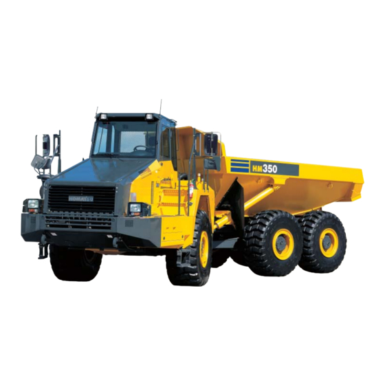
Summary of Contents for Komatsu ecot3 HM350-2
- Page 1 GEN00041-03 Field Assembly Instruction ARTICULATED HM350 DUMP TRUCK 2001 SERIAL NUMBERS and up...
-
Page 2: Table Of Contents
Contents 1 Drawings of removed units ............... 2 Dimensions of removed units ............1 3 Assembly procedure, necessary equipments, and schedule ..2 4 Necessary tools and equipments ............. 5 Assembly procedure No..............0100 Positioning bare machine ............0200 Installation of right and left mudgurds ........ -
Page 4: Drawings Of Removed Units
1 Drawings of removed units 1. Bare machine 2. Engine hood mirror Specifications of HM350-2 completed truck Related items Specifications Weight (kg) Overall length (mm) Overall width (mm) Overall height (mm) 31,060 3,700 Self-propelled travel 11,145 3,190 (Weight of machine) (When empty) 2 Dimensions of removed units Unit name... -
Page 5: Assembly Procedure, Necessary Equipments, And Schedule
3 Assembly procedure, necessary equipments, and schedule 1st day Hour Assembly unit (1) Positioning bare machine (4) Installing engine hood mirror (2) Installation of rear monitor (5) Adjusting N2 gas of front and rear suspensions (3) Installation of right and left mudguards Assembly procedure No. -
Page 6: Assembly Procedure No
Assembly procedure No. Positioning bare machine No.0100 1. Positioning bare machine Steering lock bar 1. Lower the bare machine from the trailer and position it on the flat ground. 2. Set the steering lock bar securely. Precautions Necessary tools Necessary equipment Name Q’ty Name... -
Page 7: Installation Of Right And Left Mudgurds
Assembly procedure No. Installation of right and left mudguards No.0200 1. Install mudguards to the right and left fenders. Part No. Part name Q'ty State of parts 56D-54-22950 GUARD, L.H. Mounted in cab 56D-54-22960 GUARD, R.H. Mounted in cab 56D-54-22970 PLATE Temporarily installed to fender 01024-81025... -
Page 8: Installation Of Rear Monitor
Assembly procedure No. Installation of rear monitor No.0300 1. Install the rear monitor assembly as shown in view Z. 2. Connect the rear monitor cable. 3. Fix the rear monitor cable as shown in view Y. Rear lamp bracket (To be fixed together with rear monitor assembly.) View Z View Y To be connected. -
Page 9: 0400 Installation Engine Hood Mirrors
Assembly procedure No. Installing engine hood mirror No.0400 1. Installing engine hood mirror Engine Hood Installed to engine hood temporarily View Z Installed to engine hood temporarily Part No. Part name Q'ty State of parts (1) 56B-54-2152A MIRROR, R.H. Mounted in cab 01024-81225 BOLT Installed to engine hood temporarily... -
Page 10: Adjusting N2 Gas Of Front And Rear Suspensions
Assembly procedure No. Adjusting N2 gas of front and rear suspensions No.0500 1. Adjusting N2 gas of front and rear suspensions Adjust the quantity of N2 gas (front and rear, 4 places). Air bleeding valve Installing position of suspension gas pouring tool N2 gas pouring valve Air bleeding hole Front... -
Page 11: A0100 Installation Of Antenna
Assembly procedure No. Installation of antenna No. A0100 1. Install antenna to top of cab. 1. KOMTRAX antenna : Install antenna to top of cab. 2. Radio antenna : Install antenna to left top of cab. Part No. Part name Q'ty State of parts (Parts list No.) 8A13-10-2100... - Page 12 Assembly procedure No. Mirror adjustment procedure Attached sheet...
- Page 14 List of check marks for inspection results ★ Carefully read the Operation and Maintenance Manual in advance to understand safety, : Acceptable : Unacceptable operation, machine operations and controls, and then carry out the following inspections. ) : Enter numeric values. : Uninspected : Not applicable : No check is required...
- Page 16 Inspection items Judgment procedures and criteria Check Remarks There should be no harsh shock when the dump body gets seated on Shock made when dump body is the frame (sensory check). lower to end *Perform this check after completing the calibration. Operate lever to RAISE position and check that it does not return to HOLD when released.
- Page 18 Inspection items Judgment procedures and criteria Check Remarks Flaw of tires (6 wheels) Tires must be free from flaw and tear. Hoist cylinders (Both sides) Plated surfaces must be free from rust, harmful flaw, spatter, paint, etc. Remarks(Reports) ・ Enter any problem found during the field inspection in this space. Calibration of dump body system Note: Before starting the calibration, make sure all adjustments of the dump body system and potentiometer have been satisfactorily completed.
- Page 19 HM350-2 ARTICULATED DUMP TRUCK Form No GEN00041-03...


Need help?
Do you have a question about the ecot3 HM350-2 and is the answer not in the manual?
Questions and answers