Table of Contents
Advertisement
Quick Links
Advertisement
Table of Contents

Subscribe to Our Youtube Channel
Related Manuals for Accuris AutoMATE 96

Summary of Contents for Accuris AutoMATE 96
- Page 1 Operation Manual V1.0 MP9604...
- Page 3 Please inspect the instrument as well as all included accessories when you first open the packaging. If you find anything damaged or missing, please contact Benchmark Scientific or your local distributor immediately. BENCHMARK SCIENTIFIC / ACCURIS INSTRUMENTS PO Box 709 Edison, NJ 08818 Phone: 908-769-5555 Website: www.benchmarkscientific.com / www.accuris-usa.com...
- Page 4 To prevent injury or voiding the warranty, the operator should not attempt to repair the instrument without explicit guidance from Accuris Instruments. If service is required, please contact Accuris Instruments or your local distributor for repair. Before powering on, confirm that the voltage used meets the electrical requirements of the instrument as stated on the rating plate.
- Page 5 Pull the connector plug from the electrical outlet immediately and contact the vendor in the event of: • Liquid entering the housing. • Abnormal operation: such as any abnormal sound or smell. • The instrument is dropped or there is any damage to the housing.
-
Page 6: Table Of Contents
Table of Contents Chapter 1 Introduction ..................... 8 1. Service Life ..............Error! Bookmark not defined. 2. Features ........................... 8 Chapter 2 Specifications ....................9 1. Product performance index ..................... 9 2. Outline Dimension ......................11 Chapter 3 Composition of Instrument ................12 1. - Page 7 2.2.2.4. Records ......................30 2.2.2.5. Preview ......................31 2.2.2.6. Running .............. Error! Bookmark not defined. 2.2.3. Settings ........................34 2.2.3.1. Parameters settings ................... 34 2.2.3.1.1. Liquid parameter ..................... 35 2.2.3.1.2. Speed parameter .................... 35 2.2.3.1.3. Default Tips ..................... 36 2.2.3.2. System ....................... 36 2.2.3.3.
-
Page 8: Chapter 1 Introduction
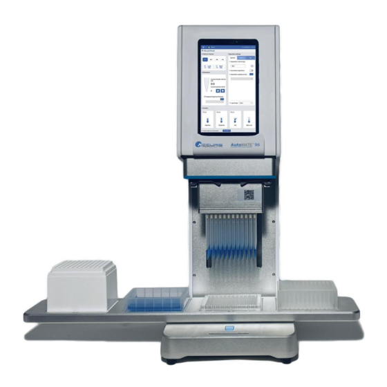
Three interchangeable heads allow for a pipetting range from 1.0µL to 1000µL. The AutoMATE 96 is compact enough to fit onto a standard lab bench or into a biosafety cabinet. 1. Key Features ➢... -
Page 9: Chapter 2 Specifications
Plate Automatic / motorized positioning Operation Tablet, basic mannual operation and progremmed operation interface Channels 8 / 96 Compatible Tips Accuris AutoMATE tips Operating Android Display 8 inch tablet, color display Instrument port USB B Power supply 100 to 240VAC, 50/60Hz, 100W... - Page 10 3. Pipetting Head Specifications MP9600-20PH MP9600-200PH MP9600-1000PH Pipette Head (20 µL) (200 µL) (1000 µL) Number of pipetting channels Pipetting 1~20 5~200 100~1000 range/µL 1µL: ≤±12% 5µL: ≤±5% 100µL: ≤±2.5% 2µL: ≤±5% 20µL: ≤±2% 500µL: ≤±1% Pipetting accuracy 10µL: ≤±1% 100µL: ≤±1% 1000µL: ≤±1% 20µL: ≤±1%...
-
Page 11: Outline Dimension
Dimensions Fig 1. Dimensions ─ ─... -
Page 12: Chapter 3 Composition Of Instrument
Chapter 3 Instrument Overview 1. Structure Fig 1. AutoMATE 96 Structure 1. Shell 2. Front casing 3. Tablet 4. Pipette 5. Front Head Plate 6. 4-position 7. Operational 8. SWITCH key 9. Instrument 10. USB motorized platform LED Indicator Base Inlet 11. -
Page 13: Replace Operation Of The Pipetting Module Structure
2. Pipette Head Installation / Replacement ① Push front casing up ② Remove the front edge ③ Loosen the locking .levers ④ Replace pipetting head ⑤ Tighten levers ⑥Replace front casing & front edge Fig 3. Pipette Head Replacement ─ ─... -
Page 14: To 384 Operation
During a program run, the AutoMATE 96 will dispense into two horizontal positions, and then instruct the user to move the 384-well microplate to the top left side of the adapter to dispense into the final 2 horizontal positions. -
Page 15: Chapter 4 Use Of Instrument
Packing List. If there are any questions about the condition of the instrument or included accessories, please make a detailed record and contact Accuris Instruments or your distributor. 1.2. Installation environment ①... - Page 16 ④ Connect the power cable to an appropriate electrical outlet and to the back power inlet on the instrument and turn on the power switch. ⑤ Power on the included tablet computer. Make sure that the battery is charged appropriately for use with the included adapter and cord. Open the Auto- Mate 96 series app on the tablet.
- Page 17 Packing List. Should there be any doubts or questions about the instrument or its accompanying accessories, such should be recorded and Accuris Instruments or the relevant distributor should be contacted. Before beginning any pipetting process, the following checklist should be completed: •...
-
Page 18: Software Usage Guide
2. Software Guide On the included Android Tablet, select the “AutoMATE™ 96” app icon to enter the application interface. Fig 4. AutoMATE™ 96 App Icon Select the user (Admin or other), enter the corresponding user password, and click “Login” to enter the main interface, as shown in the figure below. Fig 5. -
Page 19: Main Interface Of Software
Main Interface 2.1. After logging in, the main interface will display (Figure 8). On the main interface, choose one of the two pipetting modes: Manual Mode or Automated Program Mode, as shown in the figure below. Fig. 6 AutoMATE™ 96 Application Main Interface 2.1.1 Manual Mode... - Page 20 Choose "Manual mode" to enter the basic mode, as shown in the figure below. Fig. 7 Manual Mode Interface Platform Positions: The motorized platform has four positions: P1 corresponds to platform position 1, P2 corresponds to platform position 2, and so on. To change to another platform in the Manual Mode Interface, select a different platform position to highlight it blue (Figure 10);...
- Page 21 load / eject tips to the currently selected platform position. Fig. 9 Manual Mode: Tip Loading & Ejection Pipetting Functions In the Manual Mode Interface, users can toggle amongst settings for “Aspirate” , “Dispense”, and “Mix” (Figure 12). Fig 10 Manual Mode: Pipetting Functions Table 1 Legend: Manual Mode Pipetting Functions Aspiration volume Click the Aspirate volume text box, enter the volume of liquid to be...
-
Page 22: 3.Information
(µL) aspirated. Dispensation Click the Dispense volume text box, enter the volume of liquid to be volume (µL) dispensed. Mix volume (µL) Click the Mix volume text box, enter the volume of liquid to be mixed. Automatic Click on/off for the automatic aspiration function aspiration Automatic Click... - Page 23 As shown in the figure below, there are four Function Keys available : Aspirate, dispense, Mix and Blow out. The current set volume is shown in the upper left corner of each Operation button. If the Operation Setting has been set with automatic aspiration/dispense/mix with a position (mm) set, this set position will also be displayed in the upper left corner.
-
Page 24: New
Choose “Automated Program Mode” from the upper left menu to enter the Automated Program Mode, as shown in the figure below. Fig 13 Automated Program Mode Interface The Automated Program Mode offers four function buttons at the top right: New, Save as, Manage and Records. - Page 25 Fig 14 New protocol Fig 15 Select step The “Step Parameters” for the newly added step can now be set. Select a Position for the step (P1 to P4). Typically, “Load Tips” would be the first step, and for this the tips are usually positioned the at P1 (far left) position of the platform.
- Page 26 Fig 19 Labware list Fig 20 S1 P1 Load Tips After setting up the step parameters, click on “New Step” to add another step. The program can be saved by pressing the disk icon in the upper right of the screen. Steps can be modified by pressing any of the created steps in the upper left.
- Page 27 Automated Program Mode: Pause & Rinse Settings:...
-
Page 28: Save As
Automated Program Mode: Cycle Settings: 2.2.2.2. Save as To save an existing program under a new name, highlight the desired program, click the Save as option, and enter a new name. This will create a copy of the program with the new name, which can then be modified according to the user's requirements. -
Page 29: Manage
Fig 16 Save as protocol 2.2.2.3. Manage The Manage function enables users to manage the stored programs in the system. With it, they can select a program to modify, delete, or even export and import it to and from a USB flash drive. -
Page 30: Records
Fig 17 Manage interface 2.2.2.4. Records The Records function allows users to review, import, export, or delete usage data of the instrument. To view detailed usage data, users can double click on any record. If a user wants to delete a record or export/import it to/from a USB flash drive, they can click the check box on the left of the record. -
Page 31: Preview
Fig 18 Record interface This is in the wrong place: 2.2.2.5. Protocol Preview To Preview the detailed steps of a saved protocol, users can highlight the protocol and click the Preview button (as shown in Figure 37). From the preview screen, the user can click the Run button to start the protocol or press the <... -
Page 32: Running
Fig 19 Preview protocol interface Fig 20 Confirm prompt box before running 2.2.2.6. Running a protocol From the protocol list screen (Figure 20), click to highlight a single protocol, then click the “Run” button. A window will appear to confirm all consumables are placed properly before starting the run. - Page 33 Fig 21 Run interface Stop or Pause a Run During a protocol run, the user can Stop the process by clicking the Stop button. A window will appear to confirm the stopping of the run (as shown in Figure 40), and clicking OK will stop the current protocol.
-
Page 34: Settings
Fig 22 Stop prompt box Fig 23 Pause prompt box 2.2.2. Settings The Settings mode can be selected from the upper left menu. The settings interface includes three sections: parameter, system and maintenance. Fig 24 Settings 2.2.3.1. Parameters settings Parameters setting allows adjustments to Liquid parameter, Speed parameter and Default Tips, per figure 43,... -
Page 35: Liquid Parameter
Fig 25 Parameter interface 2.2.3.1.1. Liquid parameter settings Different liquids require different pipetting parameters for accurate aspiration and dispensing. The liquid parameter management interface allows adding or removing different liquids from the selection list, and adjusting parameters for the different liquids. Liquid parameters can also be imported from or exported to a USB drive. -
Page 36: Default Tips
Fig 27 Speed parameter The speed parameter interface allows adjusting the speed and acceleration values of the X axis (motorized platform) and Z axis (pipetting head). 2.2.3.1.3. Default Tips Fig 28 Default tips interface Default tips interface can set default for tips. 2.2.3.2. - Page 37 System settings are for selecting Language, Time, Screen brightness, Firmware Upgrades and Bluetooth options . For firmware upgrades, insert a USB drive with updated firmware files to perform updates (Fig 320.) Fig 29 System settings interface Fig 30 Time settings...
- Page 38 Fig 32 Bluetooth Settings Fig 31 Screen brightness settings...
-
Page 39: Maintenance
Fig 32 Upgrade settings Fig 33 Resert settings Fig 34 Bluetooth settings Fig 35 Restore the factory setting 2.2.3.3. Maintenance In the Settings mode, select “Maintenance” to enter the maintenance interface. Base calibration and Pipettor calibration adjustments should be performed by... -
Page 40: Labware
Contact the Accuris Technical Services or a local distributor for more information. To switch a pipetting heads, click Pipettor calibration and click the button “Replace module”. Follow the flow chart for pipettor head replacement in Section 2. Click... - Page 41 Fig 38 Labware main interface Fig 39 Labware management interface Fig 40 Labware new well plate interface To add a new consumable that can be selected during programming, choose the type of consumable listed under "Labware", then click the “new” box which is the box with the “+”...
- Page 42 consumable, the new brand will be automatically saved as an option for future selection (see Fig 40); Click the “Manage” button to delete a consumable. Or to import from or export to a USB drive. (see Fig 39); Basic parameters such as well shape, well volume, dimensions, and liquid levels, can be adjusted (see Fig 41, Fig 420, Fig 43).
-
Page 43: User Settings
2.2.4. User Settings Account Admin Switch User Fig 44 User settings interface Clicking on the user name in the upper left corner to see user options, including Account Administration and Switch User, as shown in the image above. 2.2.5.1. User settings Per Fig 44, the Account Admin icon to enter user settings interface. - Page 44 Fig 46 User manage interface Fig 47 Change username interface Fig 48 Reset password interface Fig 49 Delete interface...
-
Page 45: Change User
Fig 50 Add user interface Table 2 Function Click to change the current user name (maximum of 16 characters can be used); See Fig 47 Click to change the password for the user (maximum of 10 characters, including digits and case-sensitive letters) See Fig Click, to delete a user. -
Page 46: Switch Button Function
Fig 51 Change interface 2.2.5. SWITCH button function Fig 52. SWITCH button... -
Page 47: Chapter 5 Product Maintenance
The SWITCH button is located on the base of the instrument and has the following functions: 1. In Manual Mode, the switch button is used to Aspirate and Dispense. If the Current Pipette Volume is 0.0 (no liquid in the tips) then the SWITCH button will activate aspiration. -
Page 48: Regular Maintenance
If any screws have become loose, please tighten them. 4. Annual maintenance Contact the Accuris Instruments, your authorized distributor or authorized service provider for any necessary maintenance, including but not limited to the following items: 1) Check that the moving platform is level and operating smoothly. -
Page 49: Software Error Alarm List
Power Switch Tablet not Replace switch failure connecting to Instrument Fuse blown Replace fuse Contact distributor or Other Accuris Service Dept. File software Contact distributor or installation missing Accuris Service Dept. Contact distributor or Others Accuris Service Dept. Controller failure... - Page 50 E119 Over temperature. Short circuit in motor. E107 Failed to leave zero. E413 Failed to move to destination. E114 Failed to return zero. E403 Memory is damaged. E713 Motor data is lost. E723 Motor data error. E733 Calibration data is lost. E743 Calibration data error.
Need help?
Do you have a question about the AutoMATE 96 and is the answer not in the manual?
Questions and answers