
Related Manuals for PoolPak MPK Series


Summary of Contents for PoolPak MPK Series
- Page 1 Installation, Operation and Maintenance MPK Series FORM #: SVW07-MPKIOM-20170601 SUPERCEDES: SVW07-MPKIOM-20170331 UPDATED: JUNE, 2017 © 2017 PoolPak LLC. All rights reserved.
-
Page 2: Table Of Contents
With more than 45 years of experience in indoor pool dehumidification equipment manufacturing, PoolPak LLC is the most well-known brand in the ® industry. Our people and products work daily to improve the quality and comfort of indoor pool environments. PoolPak dehumidification solutions include ®... - Page 3 Remote Exhaust Fan Interlock (S Only) (20) ....................38 Auxiliary Pool Water Heating System (21) ....................38 Alarm Output (22) .............................39 Auxiliary Air Cooling System (23) .......................39 Auxiliary Air Heating System (24) .......................39 © 2017 PoolPak LLC. All rights reserved. MPK Series - Installation, Operation and Maintenance |...
- Page 4 Pool Water Piping and Installation .......................40 PoolPak Pool Water Circulation Loop ......................40 Auxiliary Water Heater (Field Supplied) .......................40 Main Pool Water Pump and PoolPak Pool Water Loop Pump Interlocks ............40 Pool Water Isolation Valves ........................40 Pool Water Pressure Transducer ........................40 Pool Water Piping Composition ........................
- Page 5 Table 4-1. Pipe Sizes for Remote Refrigerant Condensers ................47 Table 4-2. Remote ACC Refrigerant (R-410A) Charge ..................48 Table 4-3. Refrigerant (R-410A) Charge for Different Line Sizes ...............48 Table 5-1. Pool Water Chemistry .........................82 © 2017 PoolPak LLC. All rights reserved. MPK Series - Installation, Operation and Maintenance |...
- Page 6 Figure 5-26. Utilities Menu - Set Time and Date .....................73 Figure 6-1. PoolPak Control Panel ........................84 Figure 6-2. Multiple Unit Connection Schematic ....................85 Figure 6-3. Field Wiring - Communications ....................85 Figure 6-4. MPK Field Wiring ........................86 | MPK Series - Installation, Operation and Maintenance www.poolpak.com | 800-959-7725...
-
Page 7: Important
However, please check at the earliest opportunity that the product has arrived in good condition and that no damage occurred during shipping. If any damage is suspected, contact the carrier to file a claim. If the product is to sit in storage for a length of time before installation, contact PoolPak Service department for proper storage guidelines. -
Page 8: Section I: Indoor Pool Application
In its less obvious forms, moisture may penetrate walls and ceilings and cause rot that becomes noticeable only when large scale structural failure occurs. Humidity levels are also a major factor in the comfort of pool users. | MPK Series - Installation, Operation and Maintenance www.poolpak.com | 800-959-7725... -
Page 9: Indoor Air Quality
55 to 60 Therapy Pool 86 to 92 55 to 60 Whirlpools 99 to 104 55 to 60 Normally max 86°F to minimize overheating of occupants © 2017 PoolPak LLC. All rights reserved. MPK Series - Installation, Operation and Maintenance |... -
Page 10: Pool Water Chemistry
Pool water chemistry is a part of daily maintenance and it is recommended that the users follow the current National Spa Indoor Pool Water and Pool Institute standards. For more information, see the PoolPak Educational Library article ®... -
Page 11: Section Ii: Principles, Functions And Features
System’s major function is to dehumidify the pool enclosure air through a vapor compression cycle. During this cycle the PoolPak System recycles the sensible and latent heat and places it back into the pool water and air as needed. This recycling process saves money and keeps your pool environment efficient and safe. -
Page 12: Room Dew Point Control
See Figure 2-1 for reference. The CPCS uses dew point control to operate the PoolPak unit and maintain the moisture level below the setpoint. The space dry bulb temperature and relative humidity determine the dew point temperature. -
Page 13: Poolpak Operation
See Figure 2-2 to illustrate the following paragraphs. Refrigerant-Side Operation The PoolPak® draws in warm, moist air from the pool enclosure. This air passes through the evaporator (dehumidification) coil and gives up heat energy to the refrigerant which is in a cool, liquid state. This exchange of energy causes the air temperature to fall below its dew point, resulting in moisture condensation on the evaporator coil. - Page 14 Figure 2-2. MPK System Schematic | MPK Series - Installation, Operation and Maintenance www.poolpak.com | 800-959-7725...
-
Page 15: Cpcs Control Functions
Air Flow Monitoring and Control The best way to control building pressure is by measuring and controlling airflow rates. The PoolPak system employs factory mounted VFD or EC motors on the supply fan array, exhaust fan, and purge fans to modulate airflow. The controller receives feedback from fan inlet measuring stations and the outdoor air measuring station to continuously monitor the outside air, exhaust air, purge air, and supply air flows. -
Page 16: Humidity Control
Whenever available, the economizer mode brings in favorable outside air to satisfy the pool room requirements. When economizer is not available, the PoolPak unit performs mechanical dehumidification. The PoolPak provides full proportional control of relative humidity by staging unit capacity. The humidity controller energizes the compressor. -
Page 17: Cold Surface Temperature Hunidity Reset
100% outside air is drawn into the PoolPak. All the heat recovered in the PoolPak unit refrigerant is transferred to the supply air in the air reheat condenser. -
Page 18: Smart Pump Control (Optional)
During times when the pool water requires more heat than is available from the pool water condenser, the PoolPak® activates the auxiliary pool water heater. An auxiliary pool water heater must be supplied as part of the pool water pump and filter system. -
Page 19: Purge Mode (Sep)
Purge Mode (SEP) The PoolPak has a purge cycle to fully ventilate the natatorium at the airflow (CFM) specified for the unit’s supply fan. The purge cycle is programmable by the owner as necessary to ventilate the natatorium after shocking the pool. -
Page 20: Features And Options
• Integral air cooled condenser and associated refrigerant piping • Integral chilled water coil and valve • Remote exhaust fan control • Building automation system connection (LonWorks, Modbus, or BACnet) • Freeze protection • Smart Pump Control | MPK Series - Installation, Operation and Maintenance www.poolpak.com | 800-959-7725... -
Page 21: Optional Field Installed Features
• Remote exhaust fan Selection PoolPak unit selection software is more than an equipment sizing program. It is designed to accurately calculate the entire moisture load for your application. The program incorporates the key design parameters, including ASHRAE ventilation requirement, to help guide the user in meeting the necessary codes. The program also calculates the ventilation load with the outside air airflow requirement that is specified. -
Page 22: Section Iii: Sizing And Performance
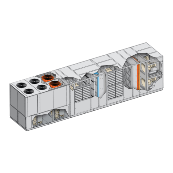
PoolPak Unit Dimensions and Weights Figure 3-1. MPK Dimensional Isometric View REAR RIGHT VIEW VIEW LEFT VIEW FRONT VIEW Refer to project specific unit drawings for dimensions and weights. | MPK Series - Installation, Operation and Maintenance www.poolpak.com | 800-959-7725... -
Page 23: Mpk Performance Summary
Circuit 3 B - cabinet B030 B035 B040 B045 B050 C - cabinet C035 C040 C045 C050 C060 C070 D - cabinet D060 D070 D080 D090 © 2017 PoolPak LLC. All rights reserved. MPK Series - Installation, Operation and Maintenance |... -
Page 24: Poolpak Remote Acc Specifications
575-3-60 22.8 23.8 Remote ACC product drawings are available on the PoolPak website in the MPK Product Drawings folder Non-PoolPak Provided Air-Cooled Consenser Selection Procedure The procedure for selecting an optional remote air-cooled condenser is: 1. Find the unit’s total heat rejection capacity from the MPK Unit Performance table. -
Page 25: Remote Cooling Tower Condenser Sizing And Performance
B - cabinet - B030, B035, B040, B045, B050; C - cabinet - C035, C040, C045, C050, C060, C070; D - cabinet - D060, D070, D080, D090 © 2017 PoolPak LLC. All rights reserved. MPK Series - Installation, Operation and Maintenance |... -
Page 26: Water Cooled Condenser Sizing And Performance
Model Water (ft) Water (ft) 1060 1220 1320 Maximum 90 °F EWT Maximum 55 °F EWT Cleanable, vented condenser Spiral, vented condenser Heat rejection at 120 °F Condensing Temperature | MPK Series - Installation, Operation and Maintenance www.poolpak.com | 800-959-7725... -
Page 27: Poolpak Pool Water Condenser
1320 Partial Water Condenser Cleanable, vented condenser (double wall) D-cabinet only. Spiral, vented condenser (double wall). Minimum required pool water flow measured at the unit. © 2017 PoolPak LLC. All rights reserved. MPK Series - Installation, Operation and Maintenance |... -
Page 28: Poolpak Auxiliary Gas Furnace Option
30.0 23.0 40.0 10.0 20.0 20.0 30.0 23.0 40.0 23.0 40.0 23.0 40.0 Actual airflow allowed is determined by the cabinet size (B, C or D) and model chosen | MPK Series - Installation, Operation and Maintenance www.poolpak.com | 800-959-7725... -
Page 29: Section Iv: Installation
If a field-furnished auxiliary space heating coil is installed, the control for this heater must be field wired to the PoolPak control panel as shown in the field wiring diagram (Figure 6-3). -
Page 30: Handling
Rigging PoolPak units require the use of spreader bars that are at least as wide as the unit. Care must be taken to prevent damage from the chains or slings used in rigging. In general, two to four lifting points are provided on each side of the unit, depending on the unit size and length. -
Page 31: Inspection
This power connection feeds the auxiliary electric heating coil. With this option, the contractor is required to supply and install a second fused disconnect. PoolPak MPK units are available in single and dual point power supply options. The 208V option is dual point power only. See illustrations. -
Page 32: Control Wiring
The condensate may be piped to a drain or returned to the pool if local codes allow. If returned to the pool, the condensate should be piped to the skimmer. PoolPak LLC recommends neither for, nor against, the practice of returning condensate to the pool. -
Page 33: Curb Mounting
Curbs have been designed specifically for the PoolPak® product line. Contact factory for roof curb dimensions. The outside dimensions of the curb are such that the base of the PoolPak® overhangs the edge of the curb on each side. This aids in preventing rain water, running down the sides of the unit, from getting between the base of the PoolPak and the curb. -
Page 34: Cpcs Controls Field Wiring
RIU in the natatorium will not be covered under warranty. The CPCS includes a 7-foot long, black RJ25 cable. If the RIU is to be mounted directly to the PoolPak unit, this cable can be plugged directly into port J10 on control module CM1 in the PoolPak® control panel. -
Page 35: Multi-Unit Network Connection (2)
Multi-Unit Network Connection (2) The CPCS utilizes a proprietary, private network to coordinate with other PoolPak units operating in the same space. This allows up to five PoolPak units to coordinate operation using a master/slave scheme. The PoolPak units are connected to each other by daisy-chaining the three terminals of T15. -
Page 36: Cold Surface Temperature Sensor (4)
Wire as shown on the field-wiring diagram. Electrical connection should be made with two-conductor (one shielded, twisted pair), 16-20 AWG copper cable. Connect the shield drain wire to ground at the PoolPak control panel end only. Supply Air Temperature Sensor (5) This sensor measures the air temperature leaving the PoolPak unit to provide indication of possible freeze damage to water coils in the unit. -
Page 37: Remote Exhaust Fan Status (9)
The CPCS provides a signal to control a proportional 3-way valve for an auxiliary air cooling system. Terminal block T12.1-3 provides the analog signal for control of a chilled water valve. © 2017 PoolPak LLC. All rights reserved. MPK Series - Installation, Operation and Maintenance |... -
Page 38: Auxiliary Hot Water Control Valve (17)
T12.4-6 provides the analog signal for control of a hot water or steam valve. Normally, this valve is factory-mounted and wired inside the PoolPak unit. However, if a remote valve is used, it can be connected directly to the PoolPak® control panel. Terminal block T12 provides 24 VDC power and a control signal. -
Page 39: Alarm Output (22)
The auxiliary heating system is normally factory-installed inside the PoolPak unit. In this case, all interface wiring between the CPCS and the heater is factory-installed. If the PoolPak® is not equipped with an auxiliary heating option, the CPCS provides contact closures to control three discrete stages of auxiliary air heating. The contacts may be directly connected to the heater’s control circuit provided it is 115 VAC maximum and the current does not... -
Page 40: Pool Water Piping And Installation
PoolPak® unit. Particular attention must be given to venting when the PoolPak® unit is installed above the level of the main pool water system. When designing a system that has over 20 to 30 feet of vertical rise, the system should be considered to be open (size pump accordingly, assuming no gravitational assistance). -
Page 41: Pool Water Piping Composition
35°F. Insulate all piping. Insulation must be sealed at all seams. NOTE Power for the field-installed heat tape must be supplied external to the PoolPak unit. Figure 4-5. Pool Water Piping Schematic POOL WATER... -
Page 42: Condensate Drains
35°F to protect against freezing. • For outdoor units, insulate all external condensate piping. Insulation must be sealed at all seams. • For additional questions or concerns regarding installation of condensate drains, please contact PoolPak Service. NOTE Power for the field-installed heat tape must be supplied external to the PoolPak unit. - Page 43 WITH SUITABLE PVC PLUG 1/2 INCH MINIMUM MAX POSITIVE STATIC PRESSURE (INCHES W.C.) + 1/2 INCH MINIMUM NOTE: NOT TO SCALE MINIMUM SCHEDULE 40 PVC © 2017 PoolPak LLC. All rights reserved. MPK Series - Installation, Operation and Maintenance |...
-
Page 44: Remote Air Cooled Condenser
Figure 4-9. Remote ACC Installation Around Walls or Obstructions AIR FLOW 6 FT MIN. | MPK Series - Installation, Operation and Maintenance www.poolpak.com | 800-959-7725... -
Page 45: Multiple Units
“Units in Pits”. Figure 4-12. Remote ACC Installation When Installing Units Near Decorative Fences AIR FLOW 6 FT 6 FT 1” MIN. MIN. MIN. © 2017 PoolPak LLC. All rights reserved. MPK Series - Installation, Operation and Maintenance |... -
Page 46: Field Installed Piping
• The highest point in the discharge line should be above the highest point in the condenser coil. • The hot gas line should loop toward the floor if the condenser is located above the PoolPak unit, especially if the hot gas riser is long. - Page 47 Above chart is for lineset length less than 100 ft and ACC located less than 50ft above unit or 20ft below unit. Failures due to a piping layout not within these limits nor receiving prior PoolPak Factory approval will not be covered under PoolPak warranty.
- Page 48 Refrigerant and Oil Charging: • PoolPak units are shipped with the required charge for self contained operation only. The remote ACC option does NOT provide the refrigerant charge or oil required for the ACC and line sets. • Refer to the below remote ACC and line size charging charts to calculate the additional charge required.
- Page 49 PoolPak MPK Series IOM ® Page Intentionally Left Blank © 2017 PoolPak LLC. All rights reserved. MPK Series - Installation, Operation and Maintenance |...
-
Page 50: Section V: Operation
Remote Interface Unit (RIU) Features The PoolPak CPCS control system includes a Remote Interface Unit (RIU) display/keypad panel that can be located remotely from the unit for the convenience of the owner. For wiring and installation, see the CPCS Controls Field Wiring section. -
Page 51: Cpcs Controller Features
See the Communications section for more details. • Unit Address (pLAN): This feature is for adjusting the controller address and is used specifically for CPCS Network Operation. © 2017 PoolPak LLC. All rights reserved. MPK Series - Installation, Operation and Maintenance |... -
Page 52: Multi-Unit Network Operation
When prompted “OK?”, select “Y” to save the configuration and to exit. The RIU will go blank and then beep several times before bringing up the normal status display. | MPK Series - Installation, Operation and Maintenance www.poolpak.com | 800-959-7725... -
Page 53: Communications
RAP. The RAP becomes active upon application of power at unit startup. The remote interface is then viewable by PoolPak service technicians to quickly handle any alarm conditions or to remotely troubleshoot the unit from the factory. -
Page 54: Fault Condition
Fault Condition When properly installed according to the instructions in this manual, the PoolPak control system will perform as designed and will provide a pool environment that is both comfortable and cost effective. However, in the unlikely event that the system does not function properly, the controller has many features that will help a service technician resolve the issue. -
Page 55: Controller Navigation
• ONLINE – Unit is connected to at least one other device on the network. This could be a keypad. • OFFLINE – Unit does not see any other network devices. © 2017 PoolPak LLC. All rights reserved. MPK Series - Installation, Operation and Maintenance |... -
Page 56: Detailed Status
• Sup Air = Supply Air Flow, Actual (Setpoint) kCFM • Exh Air = Exhaust Air Flow, Actual (Setpoint) kCFM • Pur Air = Purge Air Flow, Actual (Setpoint) kCFM | MPK Series - Installation, Operation and Maintenance www.poolpak.com | 800-959-7725... - Page 57 • Ax = Auxiliary Stages Requested (Available) for Heating, Cooling, or Dehumidification • Mx = Mixing Box Stages Requested (Available) for Cooling or Dehumidication • Tot = Total Stages Requested (Available) for Heating, Cooling, or Dehumidification © 2017 PoolPak LLC. All rights reserved. MPK Series - Installation, Operation and Maintenance |...
-
Page 58: Set Point
• Min Out Air Amt = Minimum Outside Air Amount: default – 25%, range: 0-100% • Max Out Air Amt = Maximum Outside Air Amount: default – 100%, range: 0-100% | MPK Series - Installation, Operation and Maintenance www.poolpak.com | 800-959-7725... -
Page 59: Schedules
Contact factory before changing these settings as improper settings may cause equipment damage. Digital Inputs Figure 5-15. Digital Inputs - Smoke Purge screen © 2017 PoolPak LLC. All rights reserved. MPK Series - Installation, Operation and Maintenance |... - Page 60 • Pool1 Aux Water Heat • Pool2 Aux Water Heat • Smart Pump Output 1 • Cpr1 ACC Fan Enable • Cpr2 ACC Fan Enable • Cpr3 ACC Fan Enable | MPK Series - Installation, Operation and Maintenance www.poolpak.com | 800-959-7725...
- Page 61 – Some of the sensors have this additional parameter. This is for additional sensor calibration/dampening. Do not change this value except under the instruction of PoolPak® authorized service technician. In addition, the Supply, Purge, and Exhaust air flow sensor screens display the below parameters for help during initial air balancing.
- Page 62 Tol = 005.0, Min = 000.0, Max = 069.2 • PoolB Wtr PD - Water Pressure Drop for condenser section “PoolB” (ft of water) Tol = 005.0, Min = 000.0, Max = 069.2 | MPK Series - Installation, Operation and Maintenance www.poolpak.com | 800-959-7725...
-
Page 63: History
POOL T – Pool Water Temperature (°F) MIXBOX – Mixing Box Position (%) AUX HEAT – Auxiliary Heat Stages AUX COOL – Auxiliary Cool Stages © 2017 PoolPak LLC. All rights reserved. MPK Series - Installation, Operation and Maintenance |... - Page 64 CODE – Factory Use Only DISCH P – Discharge Refrigerant Pressure (psi) SUCT P – Suction Refrigerant Pressure (psi) LIQ T – Liquid Refrigerant Temperature (°F) SUCT T – Suction Refrigerant Temperature (°F) | MPK Series - Installation, Operation and Maintenance www.poolpak.com | 800-959-7725...
-
Page 65: Unit Configuration
Max Ctl Spd – Maximum Control Speed – 1950 RPM (Range 0 to 3000) Contact Factory before adjusting the below values: • Ctl Dband – Control Deadband – 00.0 kCFM (Range 0 to 10.0) © 2017 PoolPak LLC. All rights reserved. MPK Series - Installation, Operation and Maintenance |... - Page 66 • Maximum kCFM – Maximum Airflow – 21.6 kCFM (Range 0 to 99.9) • Run Cur Tol – Fan Proof Current – 002.5 A (Range 0 to 999.9) D cabinet only | MPK Series - Installation, Operation and Maintenance www.poolpak.com | 800-959-7725...
- Page 67 • Ctl Dband – Control Deadband – 00.0 kCFM (Range 0 to 99.9) • Ctl Upd Time – Control Update Time – 05000 ms (Range 0 to 32767) • Ctl Anti-Bump – Control Anti-Bump? Off or On © 2017 PoolPak LLC. All rights reserved. MPK Series - Installation, Operation and Maintenance |...
- Page 68 • Pool2 Aux DB – On/Off Deadbands for Auxiliary Pool Water Heating of Pool 2 – 0.7 /-0.2 (Range -9.9 to 9.9) Aux Air Heating – Auxiliary Air Heating Configuration • Sys Type – Type of Auxiliary Heating System Installed • None – No Aux Heat Installed | MPK Series - Installation, Operation and Maintenance www.poolpak.com | 800-959-7725...
- Page 69 • Aux Cool First – Yes or No – This parameter determines if the Auxiliary Cooling system or compressor is the first stage of space cooling. On a call for both space cooling and dehumidification, compressor will always be first. © 2017 PoolPak LLC. All rights reserved. MPK Series - Installation, Operation and Maintenance |...
- Page 70 Space Temp Ctl – Space Temperature Control Setting • F/W Cool - Flywheel Air Cooling mode - 00.0 (Range 00.0 to 30.0) - This parameter controls the PoolPak flywheel air conditioning feature. A setting of 00.0 disables flywheel cooling. A setting of 05.0 or greater activates flywheel cooling.
-
Page 71: Manual Mode
See below review of each screen. Manual Mode Overview - Screen 1 Figure 5-24. Manual Mode Screen 1 - Overview © 2017 PoolPak LLC. All rights reserved. MPK Series - Installation, Operation and Maintenance |... - Page 72 • % Open – The percent of outside air in the supply air (Range 0 to 100.0) • Exh Loc – Exhaust Location B4Evp (Before Evaporator) or AftEvp (After Evaporator) | MPK Series - Installation, Operation and Maintenance www.poolpak.com | 800-959-7725...
-
Page 73: Utilities
The Utilities menu is holds the following additional system settings: • Set Time and Date – Calibrating the local time and date for the PoolPak unit is important since this information is used in the Fault History log and will give the exact time a fault has occurred. -
Page 74: Airflow Balancing
The controller airflow parameters can be adjusted to properly balance the airflow entering and leaving the MPK unit. PoolPak recommends that this procedure be done at unit startup and therefore a full procedure is part of the PoolPak MPK Start Up Procedure. - Page 75 5. DC Undervolt – DC bus voltage in VFD is too low. Check for low incoming line voltage. Must be in range shown on dataplate. © 2017 PoolPak LLC. All rights reserved. MPK Series - Installation, Operation and Maintenance |...
-
Page 76: Cprfaultname
The voltage at this terminal should be between 20 and 30 VDC. The DC current in the sensor loop should be between 4 and 20 mA. • If the value is greater than the max value in the analog input configuration screen, this indicates a failed | MPK Series - Installation, Operation and Maintenance www.poolpak.com | 800-959-7725... -
Page 77: Sensorname
The controller detected a lower than expected suction pressure. This is detected by either the pressure transducer and/or the “loss of charge” low pressure switch. Please contact PoolPak Service for assistance in troubleshooting this fault condition. MotorTmp = Compressor Temperature failure The controller detected an alarm signal from the compressor protection module. -
Page 78: Fault History Log
AC proof). ANALOG INPUT In addition to the digital and analog outputs, each analog input of the CPCS controller can be configured or | MPK Series - Installation, Operation and Maintenance www.poolpak.com | 800-959-7725... -
Page 79: Digital And Analog Output Configuration
This checklist determines that the space conditions and unit condition will be suitable for startup. If the checklist is completed satisfactorily, startup and owner training can be accomplished in a single day. This pre-startup checklist will be given at the time of order acknowledgement. It can also be found in the PoolPak website, www.poolpak.com, under the Start-up and Warranty Information section of the Parts &... -
Page 80: Owner Training
If special access is required to access the site, PoolPak service must be made aware of special access requirements at the time of 2 week notice. PoolPak Service will also ask for site contact information to provide to the startup technician. -
Page 81: Maintenance
1. Daily logging of pool water chemistry is typically required by local state health codes and may be requested by PoolPak in order to determine proper pool water chemistry maintenance. These logs should include both free chlorine and total chlorine measurements at a minimum. -
Page 82: Monthly Maintenance
200 - 400 1000 Calcium Acid (ppm) 30 - 50 30 - 50 For more information on pool water chemistry, see the PoolPak Educational Library article “Indoor Pool Water Chemistry”. Monthly Maintenance Perform the following on a monthly basis: NOTE To prevent personal injury, disconnect all electrical power to the unit prior to performing any of the following maintenance procedures. -
Page 83: Semi-Annual Maintenance
VFD. The main goal of VFD maintenance is to keep it clean, keep it dry, and keep the connections tight. The below are the general PoolPak recommended tips for maintaining your VFD. -
Page 84: Section Vi: Wiring
CATEGORY 5 AUTOMATION TWISTED PAIR SYSTEM (BAS) - 3 WIRES - 24 GAUGE MIN - 500 FT MAX LENGTH SPECIAL CABLE (BY POOLPAK) MULTIPLE UNIT NETWORK REMOTE INTERFACE UNIT CONNECTION | MPK Series - Installation, Operation and Maintenance www.poolpak.com | 800-959-7725... -
Page 85: Multiple Unit Control Schematic
TWISTED PAIR - 3 WIRES - 24 GAUGE MIN - 500 FT MAX LENGTH MPK Field Wiring - Communications Figure 6-3. Field Wiring - Communications © 2017 PoolPak LLC. All rights reserved. MPK Series - Installation, Operation and Maintenance |... -
Page 86: Mpk Field Wiring
MPK Field Wiring Figure 6-4. MPK Field Wiring | MPK Series - Installation, Operation and Maintenance www.poolpak.com | 800-959-7725... - Page 87 PoolPak MPK Series IOM ® Page Intentionally Left Blank © 2017 PoolPak LLC. All rights reserved. MPK Series - Installation, Operation and Maintenance |...
- Page 88 With more than 45 years of experience in indoor pool dehumidification equipment manufacturing, PoolPak LLC is the most well-known brand in the ® industry. Our people and products work daily to improve the quality and comfort of indoor pool environments. PoolPak dehumidification solutions include ®...
Need help?
Do you have a question about the MPK Series and is the answer not in the manual?
Questions and answers