Advertisement
Quick Links
Advertisement

Related Manuals for U-Line U-2260DWRINT-00A


Summary of Contents for U-Line U-2260DWRINT-00A
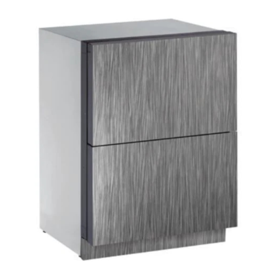
- Page 1 USER GUIDE & SERVICE MANUAL Model: U-2260DWRINT-00A...
- Page 2 USER GUIDE & SERVICE MANUAL Click on any section below to jump directly there Table of Contents Installation Integrated Panel Dimensions Integrated Panel Installation Integrated Grille Dimensions Grille / Plinth Installation...
- Page 3 U-Line has captivated those with an appreciation for the finer things with exceptional functionality, style, inspired innovations to preserve the right product, in the right place, at the right temperature. Since 2014, U-Line has been part of the Middleby and attention to even the smallest details. We are known and respected for our unwavering dedication to product design, family of brands.
- Page 4 USER GUIDE SAFETY • INSTALLATION & INTEGRATION • OPERATING INSTRUCTIONS • MAINTENANCE • SERVICE Integrated Panel Dimensions NOTICE Metric measurements rounded and optimized. When applying an integrated panel to a unit, ensure that both sides are finished in order to STANDARD PANELS prevent warping.
- Page 5 3-1/2" (89 mm) NOTE: Many cabinet manufacturers provide a ready solution for a handleless, integrated design that can be easily applied to your U-Line 3000 Series model. Consult your cabinet manufacturer for applicable design and Wooden Insert installation details. The cabinet manufacturer’s solution to...
- Page 6 USER GUIDE SAFETY • INSTALLATION & INTEGRATION • OPERATING INSTRUCTIONS • MAINTENANCE • SERVICE Handleless Integrated Panel Dimensions 1/8" (3 mm) Top Design 1/4" (6 mm) 7/8" (22 mm) Ref. R 5/8" 2-3/8" (R 16 mm) (60 mm) 23-1/2" (595 mm) Insert Notch Wooden Insert Notch Depth: 1/8"...
- Page 7 USER GUIDE SAFETY • INSTALLATION & INTEGRATION • OPERATING INSTRUCTIONS • MAINTENANCE • SERVICE EXTENDED INTEGRATED PANELS NOTICE Due to differences in surrounding cabinetry the panel may not perfectly align with drawer. The procedure below is designed to provide a finished panel that seamlessly integrates with surrounding cabinetry.
- Page 8 USER GUIDE SAFETY • INSTALLATION & INTEGRATION • OPERATING INSTRUCTIONS • MAINTENANCE • SERVICE Integrated Panel/Integrated Frame Integrated Panel U-Line U-Line Cabinet Unit Unit 3-5/16" (89 mm) 3-5/16" (89 mm) > 3-5/16" 4-5/16" (114 mm) 4-5/16" (114 mm) (> 89 mm)
- Page 9 USER GUIDE SAFETY • INSTALLATION & INTEGRATION • OPERATING INSTRUCTIONS • MAINTENANCE • SERVICE Extended Integrated Panel Dimensions Top Drawer 3/4" BACK SURFACE MUST HAVE AMPLE FLAT SURFACE (20 mm) TO MOUNT OVERLAY PANEL FLAT AND WITHOUT INTERFERENCE 23-1/2" (595 mm) 14-15/16"...
- Page 10 3. Apply double sided tape to the backside of the integrated grill (plinth strip/base fascia). Use the diagram below for reference. U-Line recommends ™ ™ tape, a high strength bonding tape.
- Page 11 USER GUIDE SAFETY • INSTALLATION & INTEGRATION • OPERATING INSTRUCTIONS • MAINTENANCE • SERVICE Integrated Panel Installation 6. Using a Phillips screwdriver, place one screw into each of the 6 pilot holes and screw down. Do not overtighten 1. Fully open drawer. screws.
- Page 12 USER GUIDE SAFETY • INSTALLATION & INTEGRATION • OPERATING INSTRUCTIONS • MAINTENANCE • SERVICE Grille - Plinth Installation REMOVING AND INSTALLING GRILLE (PLINTH STRIP/BASE FASCIA) WARNING Disconnect electric power to the unit before removing the grille (plinth strip/base fascia). When using the unit, the grille (plinth strip/base fascia) must be installed.
Need help?
Do you have a question about the U-2260DWRINT-00A and is the answer not in the manual?
Questions and answers