
Related Manuals for ESI AC64v

Summary of Contents for ESI AC64v
- Page 1 AC64v Access Device Quick Install Guide This guide instructs on installation and basic door unlocking settings of the ESI AC64v Access Device. Page 1 of 13 0455-0322 Rev A...
-
Page 2: Package Contents
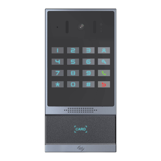
Package Contents Physical Specifications Model Device size AC64v 7 x 3.47 x 1.43 inches (177.4 x 88 x 36.2 mm) Front Panel Page 2 of 13 0455-0322 Rev A... - Page 3 Wiring Interface Open the rear case of the device, there is a row of terminal blocks for connecting the power supply, electric lock control, etc. The connections are as follows: Reference Description Number Ethernet interface: standard RJ45 interface, 10/100M adaptive, Cat5e network cable or better is recommended.
-
Page 4: Wiring Instructions
Wiring Instructions NO: Normally Open Contact COM: Common Contact NC: Normally Close Contact. Driving Mode Electric Lock Mode No electrical Electrical Connections Passive path when path when open open √ √ Electric lock (normally open type) No electrical path to open door. √... -
Page 5: Installation Diagram
Installation Diagram Panel Main Body Back Shell Wall Bracket Wall mounting Step 1: Installation preparation Check the following contents: • KM3*6 screws x3 TA4*30mm screws x5 6*30mm screw anchors x5 PM4*16mm screw x3 TM6#*20/ screw x3 Tools that may be required: •... - Page 6 Step 3: Removing hanging bracket and back shell. Detach the wall bracket downward from the device and loosen the four screws on the rear cover using a screwdriver, as shown below. Step 4: Install the wall bracket, wiring and casing 1.
- Page 7 2. Pass all the wires through the silicone plug in the middle of the bottom case. All lines should be reserved for 15~20CM length, as shown below. Note: The outlet hole of the bottom case faces down 3. Connect the cables of RJ45, power, and electric-lock to the motherboard socket as mentioned in connectors description (refer to Section 2).
-
Page 8: Flush Mounting
Flush mounting Step 1: Installation preparation Check the following contents: • PM3*3mm screws x5 PM3*4mm screws x5 6*30mm screws anchors x5 KB3*10mm screws x3 TA4*30mm screws x5 Tools that may be required: • Phillips screwdriver, hammer, RJ45 crimper Electric impact drill with an 8mm drill bit Drywall saw Flush mounting the device requires a box to be recessed into the wall as shown in the diagram below. -
Page 9: Accessing Web Interface
Step 1: Log in the access device Input IP address (e.g. http://192.168.1.128) into address bar of PC’s web browser. For eSIP, default user and password are admin/admin. For eCloud, default user and password are admin/SIPstn@ESI. Step 2: Add the SIP account. - Page 10 Step 3: Setting DSS key Set the DSS key as shown below for a quick start. Click “Apply” to save this setting. Type: Memory Key. Number 1: The DSS Key will dial to this Number 1. Number 2: If Number 1 is unavailable, it will be forwarded to Number 2. Line: Working line. Subtype: Speed dial Step 4: Access Device Setting Page 10 of 13...
- Page 11 Door Unlocking Settings RFID Card •Step 1: Access control settings on web page>EGS Setting>Add Card Rule. Select "Type" ("Normal" card provides door opening function, “Add” card and “Del” card provides add and delete card function, Default “Normal” card) •Step 2: Enter your name and card number (just enter the first 10 digits of the card number), and click "Add"...
- Page 12 Remote Password Step 1: Set access control on the web page. Go to EGS Setting>Password>Add password rule. • Select "Remote” Step 2: Enter the Name, Password and Number, Press Add to Password Table. • Step 3: The owner answers the access control call and presses " * " (default password) or "123456" •...
- Page 13 Local Password Step 1: Configure access on Web>EGS Setting>Password>Add password rule. Select "Local" (only • the AC64v supports local password access). Step 2: Enter the Name and Password, Press Add to Password Table. • Step 3: Owners and visitors can open the door by entering "6789" (default password) or "123456"...
Need help?
Do you have a question about the AC64v and is the answer not in the manual?
Questions and answers