Table of Contents
Advertisement
Available languages
Available languages
Quick Links
Advertisement
Chapters
Table of Contents

Summary of Contents for Spohn & Burkhardt VCS0
- Page 1 Joystick VCS0 Joystick VCS0 Betriebsanleitung Operating Instructions...
- Page 2 Sprachen/Languages Deutsch – Originalbetriebsanleitung ............3 English – translation of the German original ......... 51 Impressum Spohn & Burkhardt GmbH & Co. KG Web: www.spobu.de Tel.: +49 7344 171-0 Mauergasse 5 Mail: info@spobu.de 89143 Blaubeuren Germany Schutzvermerk (DIN ISO 16016:2017-08) Weitergabe sowie Vervielfältigung dieses Dokuments, Verwertung und Mitteilung seines Inhalts sind verboten, soweit nicht ausdrücklich gestattet.
-
Page 3: Table Of Contents
4.4.3. Joystick VCS0 Antrieb ........................11 4.4.4. Joystick VCS0 – Schaltspiele ......................12 4.5. Maßbilder ........................13 4.5.1. Joystick VCS0 – Grundausführung ..................13 4.5.2. Joystick VCS0 S1 – Ausführung mit Stulpenhalterrosette ..........14 Montage .......................15 5.1. Mechanische Montage ....................15 5.1.1. Maße Einbauöffnung ........................15 5.1.2. Joystick VCS0… mit Rosettenhalter ..................16 5.1.3. - Page 4 Reparatur ......................30 Demontage ....................31 9.1. Elektrische Anschlüsse lösen ................31 9.2. Mechanische Demontage ..................31 9.2.1. Joystick VCS0… mit Rosettenhalter ..................31 9.2.2. Joystick VCS0… mit Gummistulpe S3 ..................32 9.2.3. Joystick VCS0 S1… ........................33 10. Entsorgung ....................33 11. Mitgeltende Dokumente ................33 12. Ersatzteile .....................34 Anhang A.
-
Page 5: Sicherheit
1. Sicherheit 1.1. Dokumentation Die vorliegende Betriebsanleitung ist Teil des Produktes und enthält alle Informationen zur mechani- schen Montage, zum elektrischen Anschluss sowie zu Betrieb und Wartung des Gerätes. Die Betriebsan- leitung muss während der Lebensdauer des Gerätes dem jeweiligen Benutzer stets in einem leserlichen Zustand zugänglich sein. -
Page 6: Sicherheitshinweise
Vor jeder Arbeitsaufnahme muss die ordnungsgemäße Funktionsfähigkeit des Gerätes geprüft werden. Vorsicht! Achten Sie darauf, dass keine zu große Kraft auf den Joystick VCS0 ausgeübt werden kann. Der Joystick VCS0 darf nicht als Körperstütze oder Einstiegshilfe verwendet werden. Vorsicht! Achten Sie bei der Montage des Joysticks VCS0 darauf, dass ein ergonomisches Bedienen des Joysticks VCS0 gewährleistet ist. -
Page 7: Transport, Verpackung Und Lagerung
Achtung! Achten Sie darauf, dass alle Leitungen ordnungsgemäß ohne Knicke und Scheuerstellen verlegt sind. Achten Sie darauf, dass die Leitungsmarkierer nicht entfernt werden bzw. markieren Sie neue Leitungen, sodass eine Zuordnung möglich ist. Fassen Sie die Leitungen ggf. mit Ka- belbindern zusammen. -
Page 8: Beschreibung
Abbildung 1. Joystick VCS0 – Typenschlüssel 4.2. Varianten Das Baukastensystem für den Joystick VCS0 ermöglicht eine optimale Konfiguration für den individuelle Einsatz und die Anforderungen des Betreibers. Varianten und Kombinationsmöglichkeiten, siehe Anhang A. „Beispiele für Varianten und verfügbare Ein- bauten“, Seite 41. -
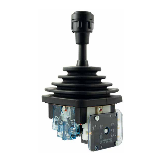
Page 9: Übersicht
4.3. Übersicht 5; 22 20.1; 20.2 10.1; 10.2 Abbildung 2. Joystick VCS0 – Übersicht Pos. Bezeichnung Pos. Bezeichnung Griff* ; Oberteil Isolierhülse Griff* ; Unterteil Buchse Griffstange Mutter Gummistulpe Sicherungsscheibe Frontplatte (nicht dargestellt, nur bei Vari- Lochscheibe anten mit Frontplatte) -
Page 10: Technische Daten
4.4. Technische Daten 4.4.1. Joystick VCS0 Umgebungstemperatur - 20° C bis +60° C Bemessungsbetriebsspannung (Ue in V) Bemessungsbetriebsstrom (Ie) in A AC 12 (ohm'sche Last) 50 Hz – 60 Hz AC 15 (induktive Last) 50 Hz – 60 Hz DC 12 (ohm'sche Last) 12 V 24 V – 42 V 115 V – 230 V DC 13 (induktive Last) -
Page 11: Joystick Vcs0 Antrieb
Fehlt die Angabe der Ausführung, wird Anordnung U geliefert. Antrieb/Drive E Antrieb/Drive V Anordnung/Layout: N U Y X Anordnung/Layout: N U Y X VCS0 - - AK E VCS0 - - AK V Anbaurichtung Potentiometer/Geber Mounting direction potentiometer/encoder Abbildung 3. Joystick VCS0 … – Antrieb Spohn + Burkhardt... -
Page 12: Joystick Vcs0 - Schaltspiele
4.4.4. Joystick VCS0 – Schaltspiele Schaltspiele Schaltstück – Lebensdauer mit AG-Kontakten AC 24 V im Mio. (ohmsche Last AC 230 V VCS0 Strom in A Abbildung 4. Joystick VCS0 … – Schaltspiele in Mio. Spohn + Burkhardt... -
Page 13: Maßbilder
4.5. Maßbilder Für weitere Varianten, siehe Anhang A. „Beispiele für Varianten und verfügbare Einbauten“, Seite 41. 4.5.1. Joystick VCS0 – Grundausführung 107,76 Abbildung 5. Joystick VCS0 Grundausführung mit Standardgriff G41 und Gummistulpe-Halterkombination S3 – Maßbild (Maße in mm) Spohn + Burkhardt... -
Page 14: Joystick Vcs0 S1 - Ausführung Mit Stulpenhalterrosette
4.5.2. Joystick VCS0 S1 – Ausführung mit Stulpenhalterrosette Abbildung 6. Joystick VCS0 S1… – Maßbild (Maße in mm) Spohn + Burkhardt... -
Page 15: Montage
Die Montage erfolgt von unten durch die Einbauplatte. Bei Varianten mit großen Griffen (z. B. T-Griff ) muss der Griff demontiert werden. 5.1.1. Maße Einbauöffnung VCS096, S3 VCS0 S1 … VCS0 72 VCS0 S0 VCS0 S Abbildung 7. Joystick VCS0 …: Maße Einbauöffnungen (Maße in mm) Spohn + Burkhardt... -
Page 16: Joystick Vcs0
Die Stärke der Schalttafel darf maximal 5 mm betragen. 7; 8 Abbildung 8. Joystick VCS0 mit Rosettenhalter –Montage Vorarbeiten 1. Schalten Sie die Anlage spannungsfrei. 2. Bereiten Sie ggf. den Einbauraum vor, siehe Abbildung 7 „Joystick VCS0 …: Maße Einbauöffnungen (Maße in mm)“, Seite 15. Spohn + Burkhardt... - Page 17 8. Öffnen Sie den Einbauraum. Montage 1. Drücken Sie die Gummistulpe (3) zusammen und schieben Sie den Joystick VCS0 von unten durch die Einbauöffnung. 2. Drücken Sie die Gummistulpe (3) zusammen und ziehen Sie die Frontplatte (4), die Dichtung (5) und den Rosettenhalter (6) vorsichtig über die Gummistulpe (3).
-
Page 18: Joystick Vcs0
6. Öffnen Sie den Einbauraum. Montage 1. Drücken Sie die Gummistulpe (3) zusammen und schieben Sie den Joystick VCS0 von unten durch die Einbauöffnung. 2. Drücken Sie die Gummistulpe (3) zusammen und ziehen Sie den Stulpenhalter (22) über die Gum- mistulpe (3). -
Page 19: Joystick Vcs0 S1
Joystick VCS0 S1… –Montage Vorarbeiten 1. Schalten Sie die Anlage spannungsfrei. 2. Bereiten Sie ggf. den Einbauraum vor, siehe Abbildung 7 „Joystick VCS0 …: Maße Einbauöffnungen (Maße in mm)“, Seite 15. 3. Ziehen Sie die Gummistulpe (3) vorsichtig von der Stulpenhalterrosette (21). - Page 20 Montage 1. Drücken Sie die Gummistulpe (3) zusammen und schieben Sie den Joystick VCS0 mit der Stulpen- halterrosette (21) von unten in die Einbauöffnung. 2. Verschrauben Sie den Joystick VCS0 mit dem Stulpenhalterrosette (21) in der Einbauplatte. 3. Ziehen Sie die Gummistulpe (3) über die Stulpenhalterrosette (21).
-
Page 21: Elektrischer Anschluss
Joystick VCS0 – Elektrischer Anschluss 1. Stellen Sie den elektrischen Anschluss gemäß der jeweiligen Variante und des Einsatzbereiches her. 2. Schließen Sie den Einbauraum. 3. Nehmen Sie den Joystick VCS0 gemäß Kapitel 6. „Inbetriebnahme“, Seite 22 in Betrieb. Spohn + Burkhardt... -
Page 22: Inbetriebnahme
Beschädigte Joysticks VCS0 dürfen nicht betrieben werden. Prüfen Sie die Schaltpositionen/Funktionen des Joysticks VCS0 gemäß den Anforderungen des Betrei- bers. Sollten Sie Fehlfunktionen feststellen, tauschen Sie den Joystick VCS0, (siehe Kapitel 9. „Demontage“, Sei- te 31 und Kapitel 5. „Montage“, Seite 15). Spohn + Burkhardt... -
Page 23: Wartung
• Entfernen Sie ggf. vorhandene Verschmutzungen. 2. Prüfen Sie den Joystick VCS0 und seine Komponenten auf Beschädigungen. • Tauschen Sie beschädigte Joysticks VCS0, (siehe Kapitel 9. „Demontage“, Seite 31 und Kapitel 5. „Montage“, Seite 15). • Tauschen Sie beschädigte Komponenten. -
Page 24: Bewegliche Teile Fetten
Abbildung 12. Joystick VCS0 – Bewegliche Teile fetten – Schematische Darstellung Vorarbeiten 1. Schalten Sie die Anlage spannungsfrei. 2. Demontieren Sie den Joystick VCS0 gemäß Kapitel 9. „Demontage“, Seite 31. 3. Demontieren Sie die Schaltelemente gemäß Abschnitt 7.6 „Kontaktelement tauschen“, Seite 27. Bewegliche Teile fetten 1. -
Page 25: Standardgriff G41 Tauschen
Joystick VCS0 – Standardgriff tauschen Vorarbeiten 1. Schalten Sie die Anlage spannungsfrei. 2. Demontieren sie ggf. den Joysticks VCS0, siehe Kapitel 9. „Demontage“, Seite 31. Griff demontieren 1. Lösen Sie die Befestigungsschraube (11) am Griff (1). 2. Schrauben Sie das Griffoberteil (1.1) ab. -
Page 26: Gummistulpe Tauschen
Abbildung 14. Joystick VCS0 – Gummistulpe tauschen Hinweis Der Joystick VCS0 muss für den Tausch des Gummistulpe (3) nicht demontiert werden! Hinweis Im folgenden wird der Tausch der Gummistulpe (3) bei der Standardausführung des Joy- sticks VCS0 mit dem Griff (1) G41 beschrieben. -
Page 27: Kontaktelement Tauschen
4. Montieren Sie den Griff gemäß Abschnitt „Griff montieren“, Seite 25. 5. Ziehen Sie die Gummistulpe (3) über den Stulpenhalter. 6. Montieren sie ggf. den Joysticks VCS0, siehe Kapitel 5. „Montage“, Seite 15. 7. Führen Sie eine Inbetriebnahme gemäß Kapitel 6. „Inbetriebnahme“, Seite 22 durch. -
Page 28: Nockenscheibe Tauschen
Nockenscheibe tauschen Achtung! Bei Joysticks VCS0 mit Rastung sollte der Joystick VCS0 ab diesem Arbeitsschritt nicht mehr gedreht oder aufgestellt werden, da sonst Bauteile aus ihrer Position fallen könnten. 1. Entfernen Sie die Schrauben (20.1) und die darunter liegenden Sicherungsscheiben (20.2). -
Page 29: Reibbremse: Bremskraft Einstellen/Bremsscheibe Tauschen
7.8. Reibbremse: Bremskraft einstellen/Bremsscheibe tauschen Hinweis Die nachfolgende Abbildung ist ein Beispiel für einen Joystick vom Typ VCS0 mit Reib- bremse. Der Joystick vom Typ VCS0 ist in unterschiedlichen Varianten, mit einer oder zwei Nockenscheiben erhältlich. Abbildung 17. Joystick VCS0 – Reibbremse: Bremskraft einstellen/Bremsscheibe tauschen Bei nachlassender Bremskraft, kann die Reibbremse über die Schraube (24) eingestellt werden. -
Page 30: Reparatur
17 „Joystick VCS0 – Reibbremse: Bremskraft einstellen/Bremsscheibe tauschen“, Seite 29). 4. Ziehen Sie die Schraube (24) mit einem Anziehdrehmoment von 0,5 Nm fest. 5. Montieren Sie den Joystick VCS0 gemäß Kapitel 5. „Montage“, Seite 15. 6. Führen Sie eine Inbetriebnahme durch, (siehe Kapitel 6. „Inbetriebnahme“, Seite 22). -
Page 31: Demontage
1. Schalten Sie die Anlage spannungsfrei. 2. Öffnen Sie den Einbauraum. 3. Lösen Sie den Stecker bzw. die elektrischen Anschlüsse. 9.2. Mechanische Demontage 9.2.1. Joystick VCS0… mit Rosettenhalter 7; 8 Abbildung 18. Joystick VCS0 – Demontage 1. Ziehen Sie die Gummistulpe (3) vorsichtig von der Rosette (8). -
Page 32: Joystick Vcs0
Frontplatte (4) über die Gummistulpe (3). 6. Öffnen Sie den Einbauraum. 7. Drücken Sie die Gummistulpe (3) zusammen und ziehen Sie den Joystick VCS0 nach unten aus dem Einbauraum. 9.2.2. Joystick VCS0… mit Gummistulpe S3 Abbildung 19. Joystick VCS0 Grundausführung –Demontage 1. -
Page 33: Joystick Vcs0 S1
1. Ziehen Sie die Gummistulpe (3) vorsichtig von der Stulpenhalterrosette (21). 2. Lösen Sie die Schrauben. 3. Öffnen Sie den Einbauraum und ziehen Sie den Joystick VCS0 nach unten aus der Einbauöffnung. 10. Entsorgung Das Gerät ist gemäß den nationalen und internationalen Gesetzen und Vorschriften zu entsorgen. -
Page 34: Ersatzteile
12. Ersatzteile Hinweis Diese Dokumentation beschreibt nur die Standardausführung des Joysticks VCS0. In der nachfolgenden Tabelle finden Sie die Ersatzteile für alle Ausführungen. Weitere Informationen zu Montage und Demontage der Ersatzteile für die jeweilige Aus- führung entnehmen Sie der zugehörigen Dokumentation. - Page 35 1x NS0 ES106 Sicherungsblech für Muttern am Griffstängel Ø 8 mm 1x Mutter Griffoberteil HDV G41 47193 für VNS0 & VCS0 mit HDV-Taste für Hupe dicht versenkt 1x NS0 ES41D-02 Griff G41 mit Schraube für NS0 und ST1 1x NS0 ES2 Mitnehmerbuchse 1x Scheibe Lochscheibe für Griff G41...
- Page 36 Gummistulpe 54160 HS2-27 UGD für VNS0 & VCS0 1x Gummistulpe S3 für Griff UGD Gummistulpe 47177 V041N Standard für VNS0 & VCS0 & CS1 & NS3 1x Gummistulpe Gummistulpe 51999 V041K für VNS0 & VCS0 & CS1 1x Gummistulpe Gummistulpe 52000 V040KE2 für VCS0 &...
- Page 37 Ersatzteil Bezeichnung/Lieferumfang Gummistulpe 54161 HS2-27 UG / UGN für VNS0 & VCS0 1x Gummistulpe S3 für Griff UG und UGN Gummistulpenhalter komplett 54088 mit Dichtung 1x V048R2D Gummistulpenhalter komplett mit Dichtung, Rosette S3 5x Gewindefurchende Schraube 5x W1451 M4x16 TX20 Stahl 10.9 verzinkt(A3K) Linsenkopfschraube mit Flansch und Innen sechsrund für thermoplastische Kunststoffe...
- Page 38 37263 (PD550/PW55) für VCS0-Joystick 1x CS071 F Poti-Kammer für CS0 Potis Bxx, PQxx, PDxx, PBxx 1x ZR.01.014.010 Zahnrad M=1 Z=14 für VCS0 mit Poti PW55 1x CS071 FC Lagerplatte kpl für Poti PQ VCS0 1x Abdeckplatte PVC hart glasklar 2x ISO 7045 M3x10 Stahl 4.8 verzinkt Linsenschraube mit Kreuzschlitz H 2x Sicherungsscheibe S3 geschwärzt Federstahl, blank...
- Page 39 1x Dichtung 1x V0028R Rosettenhalter für VCS0 Rosette Alu 72×72 1x V0044 Rosette 72 x 72 mm Alu schwarz für VCS0 und CS1 5x W1423 4×16 10.9 A3K TX20 Senkkopfschraube mit Innensechsrund 5x DIN 7985 M3x4 Edelstahl A2 blank H Linsenschraube mit Kreuzschlitz H Rückzughebel...
- Page 40 Ersatzteil Bezeichnung/Lieferumfang Stulpenhalterrosette 47179 für VNS0 & VCS0 1x Stulpenhalter 5x Gewindefurchende Schraube 5x ISO 7380-1 M6x10 Stahl 10.9 verzinkt, blau passiviert (A2K) Schraube abgeflachter Halbrundkopf und Innensechskant Spohn + Burkhardt...
-
Page 41: Anhang A. Beispiele Für Varianten Und Verfügbare Einbauten
A.1. Joystick VCS0 – mit Potentiometer Ausführung mit • Standardgriff G41 Standardgriff • Gummistulpe V041N • Potentiometer PD550 Abbildung 21. Joystick VCS0 Ausführung mit Potentiometer PD550 – Maßbild (Maße in mm) A.1.1. Verfügbare Potentiometer für den Joystick VCS0 Potentiometer Technologie Leistung Anschluss... - Page 42 Schraubanschluss A.2. Joystick VCS0 – mit optoelektronischem Absolutwertgeber Ausführung mit • Absolutwertgeber OGF Abbildung 22. Joystick VCS0 Ausführung mit optoelektronischem Absolutwertgeber und Standardgriff G41 – Maß- bild (Maße in mm) A.2.1. Verfügbare optische Geber für den Joystick VCS0 Optischer Geber...
- Page 43 A.3. Joystick VCS0 96… Ausführung mit • Standardgriff G41 • Gummistulpe V041N • Rosette V048K3 • Rosettenhalter V048R1 Abbildung 23. Joystick VCS0 96… – Maßbild (Maße in mm) Spohn + Burkhardt...
- Page 44 A.4. Joystick VCS0 72… Ausführung mit • Standardgriff G41 • Gummistulpe V040KE2 • Rosette V0044 • Rosettenhalter V028R Abbildung 24. Joystick VCS0 72…mit Standardgriff G41 – Maßbild (Maße in mm) Spohn + Burkhardt...
- Page 45 A.5. Joystick VCS0 SO… Ausführung mit • Standardgriff G41 • Gummistulpe V040KE2 • Stulpenhaltering CS092 V0044 • Schlauchband ZY72x5 Abbildung 25. Joystick VCS0 SO… mit Standardgriff G41 – Maßbild (Maße in mm) Spohn + Burkhardt...
-
Page 46: Anhang B. Griffe Und Verfügbare Einbauten
Anhang B. Griffe und verfügbare Einbauten B.1. Griffe für den Joystick VCS0 G4T-WT G13-Z G19-Z G21-Z G21-ZV G22-V G22-ZV Standard Spohn + Burkhardt... - Page 47 G41D Rastung/ G41H G41HD G41HDFZ G41DR Selbstrückgang G41HDV G41HDVZ G41HDZ G41T G41TY G41TZ KG40 Spohn + Burkhardt...
- Page 48 KG50 KG56-IKKZ KG56-IKZ Spohn + Burkhardt...
- Page 49 Modul Hinweis Für weitere Kombinationsmöglichkeiten, siehe Kapitel 11. „Mitgeltende Dokumente“, Sei- te 33, „Produktdatenblatt VCS0“ oder kontaktieren Sie die Firma Spohn & Burkhardt GmbH & Co. KG (Kontaktdaten siehe Impressum, Seite 2). B.3. Verfügbare Bussysteme für den Joystick VCS0...
-
Page 50: Anhang C. Konformitätserklärung
Anhang C. Konformitätserklärung Spohn + Burkhardt... - Page 51 4.4.4. Joystick VCS0 – switching cycles ....................60 4.5. Dimension drawings ....................61 4.5.1. Joystick VCS0 – basic version ....................61 4.5.2. Joystick VCS0 S1 – version with boot holder escutcheon ..........62 Installation ....................63 5.1. Mechanical installation ...................63 5.1.1. Dimensions of installation opening ..................63 5.1.2.
- Page 52 Removal .......................79 9.1. Undoing electrical connections ................79 9.2. Mechanical removal ....................79 9.2.1. Joystick VCS0… with escutcheon holder ................79 9.2.2. Joystick VCS0… with rubber boot S3 ..................80 9.2.3. Joystick VCS0 S1… ........................81 10. Disposal ......................81 11. Reference documents ................81 12. Spare parts ....................82 Appendix A.
-
Page 53: Safety
1. Safety 1.1. Documentation These operating instructions are part of the product and contain all the information about the me- chanical installation, the electrical connection, as well as the operation and servicing of the device. The operating instructions must always be available, in a legible condition, to the related user for the service life of the device. -
Page 54: Safety Instructions
Caution! Make sure that an excessively high force cannot be applied to the joystick VCS0. The joystick VCS0 is not allowed to be used to support the body or as an entry aid. Caution! While installing the joystick VCS0, make sure that ergonomic operation of the joystick VCS0 is ensured. -
Page 55: Transport, Packaging And Storage
Attention! Make sure all cables are laid correctly without kinks or points where they can chafe. Make sure the cable markers are not removed and mark new cables so they can be iden- tified. Fasten together the cables using cable ties, if necessary. While laying cables, pay attention to any bending radii specified by the manufacturer. -
Page 56: Description
Potentiometers and encoders can be attached with a shaped fit by means of the use of a simple plug-in coupling or directly instead of a double contact element. Along with numerous applications in the bespoke equipment sector, the joystick VCS0 is used in cranes, control stands and in portable control consoles due to its low weight. -
Page 57: Overview
4.3. Overview 5; 22 20.1; 20.2 10.1; 10.2 Figure 2. Joystick VCS0 – overview Item Name Item Name Knob* ; top part Insulating sleeve Knob* ; bottom part Bush Stick Rubber boot Locking washer Front plate (not shown, only for variants... -
Page 58: Technical Data
4.4. Technical data 4.4.1. Joystick VCS0 Ambient temperature - 20° C to +60° C Rated operating voltage (Ue in V) Rated operating current (Ie) in A AC 12 (ohmic load) 50 Hz – 60 Hz AC 15 (inductive load) 50 Hz – 60 Hz DC 12 (ohmic load) 12 V 24 V –... -
Page 59: Joystick Vcs0 Drive
If there is no information about the version, layout U is supplied. Antrieb/Drive E Antrieb/Drive V Anordnung/Layout: N U Y X Anordnung/Layout: N U Y X VCS0 - - AK E VCS0 - - AK V Anbaurichtung Potentiometer/Geber Mounting direction potentiometer/encoder Figure 3. Joystick VCS0 … – drive Spohn + Burkhardt... -
Page 60: Joystick Vcs0 - Switching Cycles
4.4.4. Joystick VCS0 – switching cycles Switching cycles Contact – service life with AG contacts AC 24 V in millions (ohmic load AC 230 V) VCS0 Current in A Figure 4. Joystick VCS0 … – switching cycles in millions Spohn + Burkhardt... -
Page 61: Dimension Drawings
For other variants, see Appendix A. "Examples for variants and available fittings", page 89. 4.5.1. Joystick VCS0 – basic version 107,76 Figure 5. Joystick VCS0 basic version with standard knob G41 and rubber boot-holder combination S3 – dimen- sion drawing (dimensions in mm) Spohn + Burkhardt... -
Page 62: Joystick Vcs0 S1 - Version With Boot Holder Escutcheon
4.5.2. Joystick VCS0 S1 – version with boot holder escutcheon Figure 6. Joystick VCS0 S1… – dimension drawing (dimensions in mm) Spohn + Burkhardt... -
Page 63: Installation
Installation is from below though the mounting plate. It is necessary to remove the knob on variants with large knobs (e.g. T-knob). 5.1.1. Dimensions of installation opening VCS096, S3 VCS0 S1 … VCS0 72 VCS0 S0 VCS0 S Figure 7. Joystick VCS0 …: dimensions of installation openings (dimensions in mm) Spohn + Burkhardt... -
Page 64: Joystick Vcs0
Joystick VCS0 with escutcheon holder - installation Preparatory work 1. Disconnect the system from the supply of electrical power. 2. Prepare the installation space, see Figure 7 "Joystick VCS0 …: dimensions of installation openings (di- mensions in mm)", page 63. Spohn + Burkhardt... - Page 65 2. Press together the rubber boot (3) and pull the front plate (4), the seal (5) and the escutcheon hold- er (6) carefully over the rubber boot (3). 3. Fasten the joystick VCS0, the front plate (4), the seal (5) and the escutcheon holder (6) using the 4 screws M4 x 14.
-
Page 66: Joystick Vcs0
2. Press together the rubber boot (3) and pull the boot holder (22) over the rubber boot (3). 3. Fasten the joystick VCS0 to the mounting plate through the boot holder (22) using the 4 screws M4 x 14. 4. Pull the rubber boot (3) over the boot holder (22). -
Page 67: Joystick Vcs0 S1
Preparatory work 1. Disconnect the system from the supply of electrical power. 2. Prepare the installation space, see Figure 7 "Joystick VCS0 …: dimensions of installation openings (di- mensions in mm)", page 63. 3. Carefully pull the rubber boot (3) off the boot holder escutcheon (21). - Page 68 Installation 1. Press together the rubber boot (3) and push the joystick VCS0 with the boot holder escutcheon (21) through the installation opening from below. 2. Fasten the joystick VCS0 with the boot holder escutcheon (6) to the mounting plate.
-
Page 69: Electrical Connection
Joystick VCS0 – Electrical connection 1. Make the electrical connection as per the related variant and the application. 2. Close the installation space. 3. Undertake setup on the joystick VCS0 as per chapter 6. "Setup", page 70. Spohn + Burkhardt... -
Page 70: Setup
1. Disconnect the system from the supply of electrical power. 2. Check all the switching functions of the joystick VCS0. If you detect malfunctions, replace the joystick VCS0 (see chapter 9. "Removal", page 79 and chapter 5. "Installation", page 63). 6.1.2. Electrical function test Danger! The electrical function test is undertaken with the system switched on. -
Page 71: Servicing
1. Check the joystick VCS0 and its components for soiling. • If necessary, remove any soiling. 2. Check the joystick VCS0 and its components for damage. • Replace damaged joysticks VCS0 (see chapter 9. "Removal", page 79 and chapter 5. "Installation", page 63). • Replace damaged components. -
Page 72: Grease Moving Parts
Preparatory work 1. Disconnect the system from the supply of electrical power. 2. Remove the joystick VCS0 as per chapter 9. "Removal", page 79. 3. Remove the switching elements as per section 7.6 "Replacing contact element", page 75. Grease moving parts 1. -
Page 73: Replacing Standard Knob G41
Joystick VCS0 – replacing standard knob Preparatory work 1. Disconnect the system from the supply of electrical power. 2. If necessary, remove the joystick VCS0 see chapter 9. "Removal", page 79. Removing knob 1. Undo the fastening screw (11) on the knob (1). -
Page 74: Replacing Rubber Boot
Figure 14. Joystick VCS0 – replacing rubber boot Note The joystick VCS0 does not need to be removed for the replacement of the rubber boot (3)! Note In the following the replacement of the rubber boot (3) on the standard version of the joystick VCS0 with the knob (1) G41 is described. -
Page 75: Replacing Contact Element
4. Install the knob as per section "Installing knob", page 73. 5. Pull the rubber boot (3) over the boot holder. 6. If necessary, install the joystick VCS0 see chapter 5. "Installation", page 63. 7. Undertake setup as per chapter 6. "Setup", page 70. -
Page 76: Replacing Cam Disk
4. Remove the contact element (10) as per section 7.6 "Replacing contact element", page 75. Replacing cam disk Attention! On joysticks VCS0 with detent mechanism, from this work step onward the joystick VCS0 should no longer be rotated or positioned because otherwise components could fall out of position. -
Page 77: Friction Brake: Adjusting The Braking Force/Replacing The Brake Disc
7.8. Friction brake: Adjusting the braking force/replacing the brake disc Note The following figure is an example of a type VCS0 joystick with friction brake. The joystick type VCS0 is available in different variants, with one or two cam disks. -
Page 78: Repair
Make sure that the cam disks (26) are in the correct position, Figure 17 4. Tighten the screw (24) with a tightening torque of 0.5 Nm. 5. Install the joystick VCS0 as per chapter 5. "Installation", page 63. 6. Undertake setup (see chapter 6. "Setup", page 70). -
Page 79: Removal
1. Disconnect the system from the supply of electrical power. 2. Open the installation space. 3. Disconnect the connector or the electrical connections. 9.2. Mechanical removal 9.2.1. Joystick VCS0… with escutcheon holder 7; 8 Figure 18. Joystick VCS0 – removal 1. -
Page 80: Joystick Vcs0
5. Open the installation space. 6. Press together the rubber boot (3) and pull the joystick VCS0 out of the installation space from be- low. 9.2.2. Joystick VCS0… with rubber boot S3 Figure 19. Joystick VCS0 basic version – removal 1. -
Page 81: Joystick Vcs0 S1
1. Carefully pull the rubber boot (3) off the boot holder escutcheon (21) 2. Undo the screws. 3. Open the installation space and pull the joystick VCS0 out of the installation space from below. 10. Disposal The device is to be disposed of as per the national and international laws and regulations. -
Page 82: Spare Parts
12. Spare parts Note This document describes only the standard version of the joystick VCS0. In the following table you will find the spare parts for all versions. For further information on installing and removing the spare parts for the related version, refer to the related documentation. - Page 83 1x NS0 ES106 locking plate for nuts on the stick Ø 8 mm 1x nut Top part of the knob HDV G41 47193 for VNS0 & VCS0 with HDV button for horn, sealed, recessed 1x NS0 ES41D-02 knob G41 with screw for NS0 and ST1 1x NS0 ES2 drive bush 1x washer, perforated washer for knob G41 1x NS0 ES106 locking plate for nuts on the stick Ø 8 mm 1x nut...
- Page 84 54160 HS2-27 UGD for VNS0 & VCS0 1x rubber boot S3 for knob UGD Rubber boot 47177 V041N standard for VNS0 & VCS0 & CS1 & NS3 1x rubber boot Rubber boot 51999 V041K for VNS0 & VCS0 & CS1...
- Page 85 5x W1451 M4x16 TX20 steel 10.9 galvanized (A3K) pan head screw with flange and hexalobular socket for thermoplastic materials Clip 53534 for 2 contact elements for VCS0 5x clip for the connection of two CS0 double contact elements Clip 53536 for 3 contact elements for VCS0...
- Page 86 (PD550/PW55) for VCS0 joystick 1x CS071 F potentiometer clip for CS0 potentiometers Bxx, PQxx, PDxx, PBxx 1x ZR.01.014.010 gearwheel M=1 Z=14 for VCS0 with potentiometer PW55 1x CS071 FC bearing plate compl. for potentiometer PQ VCS0 1x cover plate PVC hard crystal clear 2x ISO 7045 M3x10 steel 4.8 galvanized pan head screw with cross head H...
- Page 87 Spare part Name/items supplied Cam disk 51895 for direction contact for VCS0 & CS1 1x CS061A cam disk programmed for VCS0 and CS1 for direction contact with potentiometer 2x DIN 921 M3x6 5.8 VZ TX10 flat head screw Zero contact 51903...
- Page 88 Spare part Name/items supplied Boot holder escutcheon 47179 for VNS0 & VCS0 1x boot holder 5x self-tapping screw 5x ISO 7380-1 M6x10 steel 10.9 galvanized, blue passivated (A2K) screw flattened domed head and hex socket Spohn + Burkhardt...
-
Page 89: Appendix A. Examples For Variants And Available Fittings
Version with • Standard knob G41 standard knob • Rubber boot V041N • Potentiometer PD550 Figure 21. Joystick VCS0 version with potentiometer PD550 – dimension drawing (dimensions in mm) A.1.1. Available potentiometers for the joystick VCS0 Potentiometer Type Technology Power... - Page 90 DC 24 V D-Sub connector Note For accessories for the optical encoders, see chapter 11. "Reference documents", page 81, "Product data sheet VCS0" or contact Spohn & Burkhardt GmbH & Co. KG (for contact data see Imprint, page 2). Spohn + Burkhardt...
- Page 91 A.3. Joystick VCS0 96… Version with • Standard knob G41 • Rubber boot V041N • Escutcheon V048K3 • Escutcheon holder V048R1 Figure 23. Joystick VCS0 96… – dimension drawing (dimensions in mm) Spohn + Burkhardt...
- Page 92 A.4. Joystick VCS0 72… Version with • Standard knob G41 • Rubber boot V040KE2 • Escutcheon V0044 • Escutcheon holder V028R Figure 24. Joystick VCS0 72…with standard knob G41 – dimension drawing (dimensions in mm) Spohn + Burkhardt...
- Page 93 A.5. Joystick VCS0 SO… Version with • Standard knob G41 • Rubber boot V040KE2 • Boot holder CS092 V0044 • Hose clip ZY72x5 Figure 25. Joystick VCS0 SO… with standard knob G41 – dimension drawing (dimensions in mm) Spohn + Burkhardt...
-
Page 94: Appendix B. Knobs And Available Fittings
Appendix B. Knobs and available fittings B.1. Knobs for the joystick VCS0 G4T-WT G13-Z G19-Z G21-Z G21-ZV G22-V G22-ZV Standard Spohn + Burkhardt... - Page 95 G41D detent mecha- nism/ G41H G41HD G41HDFZ G41DR self-return G41HDV G41HDVZ G41HDZ G41T G41TY G41TZ KG40 Spohn + Burkhardt...
- Page 96 KG50 KG56-IKKZ KG56-IKZ Spohn + Burkhardt...
- Page 97 Note For further possible combinations, see chapter 11. "Reference documents", page 81, "Prod- uct data sheet VCS0" or contact Spohn & Burkhardt GmbH & Co. KG (for contact data see Imprint, page 2). B.3. Available bus systems for the joystick VCS0...
-
Page 98: Appendix C. Declaration Of Conformity
Appendix C. Declaration of conformity Spohn + Burkhardt... - Page 99 Spohn + Burkhardt...
- Page 100 Spohn & Burkhardt GmbH & Co. KG Web: www.spobu.de Tel.: +49 7344 171-0 Mauergasse 5 Mail: info@spobu.de 89143 Blaubeuren Germany...
Need help?
Do you have a question about the VCS0 and is the answer not in the manual?
Questions and answers