Table of Contents

Summary of Contents for Weber Alpha HSM
- Page 1 Original instructions Alpha HSM Material number of the documentation 40058725 (GB) English Version: 12.19.17 /OKR 40058725 Weber Marking Systems GmbH Maarweg 33 D-53619 Rheinbreitbach E-Mail: info@webermarking.de http://www.webermarking.de...
- Page 2 Blank page...
-
Page 3: Table Of Contents
Content 40058725 BTA Alpha HSM Table of contents General ........................7 Overview ........................... 7 Limitation of liability ......................7 Warranty conditions ......................7 Copyright ........................... 7 Purpose and overview of the operating instructions............8 Notes regarding the operating instructions use ..............8 Service Hotline ........................ - Page 4 Content 40058725 BTA Alpha HSM Installation ........................36 Requirements regarding the installation location ................. 36 Positioning of the labeler ......................36 Attachment of the labeler....................37 Connecting the labeler ....................37 Overview of the connections on the labeler ..............38 Connection to the mains voltage ....................
- Page 5 Content 40058725 BTA Alpha HSM Presentations and operation of the menus .................. 72 Password protection ........................73 Menu structure ..........................74 Status menu ........................76 Manual feed ..........................77 Temporary setting options......................78 “Countdown“ (Set Count Down) ....................78 Configuration menu ......................79 Configuration selection.........................
- Page 6 Content 40058725 BTA Alpha HSM Mechanical errors ......................102 Correct the settings after the labeling result ..............104 Proper labeling ........................... 104 Error during the labeling ......................104 Error and warning messages ..................106 Error acknowledgment ....................... 106 Error messages .......................... 107 Warnings ............................
-
Page 7: General
This documentation or parts of the document may only be copied, photocopied, reproduced or translated into other languages for personal use. Reproduction for disclosure to third parties is not permitted without prior written consent from Weber Marking Systems GmbH. Page 7 of 112... -
Page 8: Purpose And Overview Of The Operating Instructions
Chapter 1 General 40058725 BTA Alpha HSM Purpose and overview of the operating instructions These operating instructions are designed to introduce the labeler and to facilitate its in- tended use. It contains important information for the user to ensure that the labeler is operated safely and correctly. -
Page 9: Service Hotline
Chapter 1 General 40058725 BTA Alpha HSM Messages which are shown on the display are presented in a box: Status: Label 89x36 mm Number: 0 Rest.: Fig.: 1-1 Example for display content Service Hotline The technical Service-Hotline is available 24 hours a day from Monday to Friday. In case of emergencies, a shipment of parts is possible until approx. -
Page 10: Explanation Of The Technical Terms Used
Chapter 1 General 40058725 BTA Alpha HSM Explanation of the technical terms used Technical term Explanation (Application) stroke Distance covered by the dispensing tamp when it is extended towards the product. Adhesive strips Leaked adhesive at the label edge can cause the label to adhere to the carrier paper. - Page 11 Chapter 1 General 40058725 BTA Alpha HSM Technical term Explanation Dispensing tamp (tamp) Unit that picks the label through vacuum, transports it to the product and places it there Dispensing tamp (tamp) Unit that picks the label through vacuum, transports it to the product and applies it there.
- Page 12 Chapter 1 General 40058725 BTA Alpha HSM Technical term Explanation Labeler Application system for the automatic application of labels. Labeling mode Corresponds to normal operation. The labeler is ready to dispense labels. See “Leading edge”. Leading Edge Leading edge The leading edge of a product/label is used to start a process (see “Edge detection”).
- Page 13 Chapter 1 General 40058725 BTA Alpha HSM Technical term Explanation Tamp-blow Contact-free application mode, during which the dispensing tamp takes over the printed label through vacuum, conveyed to the product and blown onto the product Tamp-on Application mode, during which the dispensing tamp takes over the label through vacuum, conveys it to the product and presses it onto the product.
-
Page 14: Safety Regulations
Chapter 2 Safety regulations 40058725 BTA Alpha HSM 2. Safety regulations Behaviour in case of emergencies The operating personnel must be familiar with handling and the locations of safety, acci- dent reporting, first-aid and rescue equipment. What to do in case of an emergency? ... -
Page 15: Intended Use
Chapter 2 Safety regulations 40058725 BTA Alpha HSM Intended use The operation reliability of the labeler is only guaranteed when used as intended. An intended use will be considered as such, if … the labeler is exclusively used for automatic labeling of moving or stationary prod- ucts. -
Page 16: Reasonably Foreseeable Improper Use
Chapter 2 Safety regulations 40058725 BTA Alpha HSM Reasonably foreseeable improper use A different use other than specified under "intended use", or any other additional use will be considered as improper use! For damages caused by improper use shall be the sole responsibility of the operator, ... -
Page 17: Sources Of Danger On The Labeler
Chapter 2 Safety regulations 40058725 BTA Alpha HSM Sources of danger on the labeler Fig. 2-1: Sources of danger on the standard labeler (LH) The following assemblies pose a risk of crushing and being drawing in: Drive unit (label feed) ... -
Page 18: Protective Devices
Chapter 2 Safety regulations 40058725 BTA Alpha HSM Protective devices Danger points can develop at the transition areas of the customer-side conveying sys- tems. Appropriate protection measures according to the machinery directive 2006/42/EG must be implemented. Separating and non-separating protective devices The labelling system doesn't require any additional protective device for the operation. -
Page 19: Safety Instructions
Chapter 2 Safety regulations 40058725 BTA Alpha HSM Safety instructions Danger through a direct or indirect contact with live parts. DANGER TO LIFE If persons come into contact with parts that have become ener- gized through malfunctions, this can lead to death. -
Page 20: Residual Risks
Chapter 2 Safety regulations 40058725 BTA Alpha HSM Risk of breakage. RISK OF INJURY Risk of material fatigue during operation due to the addition of ad- ditional weights (label rolls, tools, etc.) to the system. - Do not fasten or deposit additional weights to the system. -
Page 21: Obligations Of The Operator
Technical personnel are operators who have completed a technical training (electrical technician, mechanic). have successfully completed a training course of the Bluhm-Weber-Group. Technical personnel are entitled to to carry out repair and maintenance work on the labeler and its components in accordance with its professional qualifications. -
Page 22: Personal Protective Equipment
Chapter 2 Safety regulations 40058725 BTA Alpha HSM Personal protective equipment When working on the machine, the following protective equipment must be worn: SAFETY SHOES To protect against slipping and falling parts. PROTECTIVE WORK WEAR Tight-fitting clothing with tight sleeves and a low tensile strength, with- out protruding parts. -
Page 23: Workplaces For Operating Personnel
Chapter 2 Safety regulations 40058725 BTA Alpha HSM Workplaces for operating personnel The labeler is a fully automated system, and does not require any operator intervention for the labeling operation. Only one person is required to refill the labels. During troubleshooting (e.g. label removal...), maintenance work and repairs, operation from all sides of the system is possible, as long as this does not expose the person to any other hazards (conveying systems...). -
Page 24: Technical Specifications
Chapter 3 Technical Specifications 40058725 BTA Alpha HSM 3. Technical Specifications Dimensions min. 580 x 310 x 590 (depending on the configuration) (H x W x D in mm): Weight: 16 - 48 kg (depending on configuration, without label roll) -
Page 25: Performance Data
Chapter 3 Technical Specifications 40058725 BTA Alpha HSM max. 500 mm Performance data up to 2000 labels/min (depending on label size and configu- Application cycle rate ration) +/- 0.3 mm (relative to the repetition accuracy at the peel Application accuracy... -
Page 26: Description Of The Labeler
Depending on the type and dimensions of the product, different label formats can be used. Versions The modular concept allows for different configurations. The Alpha HSM is used as a right hand (RH) or left hand (LH) version; i.e. the label comes out of the dispenser on the right (RH) or left hand (LH) side. -
Page 27: General Overview
General overview The labeler shown here is a configuration example and can deviate from the version supplied (see also Module overview, page 28). Fig. 4-1:Alpha HSM-LH in the front view Designations UNWINDER Module for receiving and unwinding of label rolls DANCER ARM Keeps the label material evenly tensioned and regulates the unwinding speed. -
Page 28: Module Overview
Entering commands to the labeler and displaying operating states and error messages. Module overview The Alpha HSM can be configured to meet customer requirements in several ways. Below are some examples of modules: Fig. 4-2: Module examples (LH version) Page 28 of 112... - Page 29 Chapter 4 Description of the labeler 40058725 BTA Alpha HSM Module Design Unwinder Standard unwind (UM) Mechanical unwinding Unwinder Advanced (UMA) Unwinder for special installation position Unwinder Performance (UMP) Strong unwinder with quick-release axle Servo motor driven unwinder with quick-...
-
Page 30: Identification Of The Labeler Via The Nameplate
Chapter 4 Description of the labeler 40058725 BTA Alpha HSM Rewinder The rewinder unit accepts the empty carrier material. If the label liner moves, this will lead to an oscillating movement of the dancer arm, and thus control the rewinding speed. -
Page 31: Transport
Chapter 5 Transport 40058725 BTA Alpha HSM 5. Transport Delivery If the labeler is delivered by a freight carrier, please check the packaging for any damage. If any irregularities are detected, a complaint should immediately be issued to the freight carrier and also noted on the delivery note. - Page 32 Chapter 5 Transport 40058725 BTA Alpha HSM Remove the packaging material and the transport security mecha- nism only at the deployment site. Transport the labeler in its origi- nal packaging to the "labeling location". An unsecured labeler can easily tip over during transport.
-
Page 33: Storage Conditions
Chapter 5 Transport 40058725 BTA Alpha HSM Instruction This is how to transport the labeler to its utilisation site Step Approach Transport the labeler to its utilisation site (within a vicinity of 3 m). The accu- rate positioning will be carried out during the course of the installation by Bluhm Weber Group technicians. -
Page 34: Installation And Connection
Chapter 6 Installation and connection 40058725 BTA Alpha HSM 6. Installation and connection Safety instructions Danger through a direct or indirect contact with live parts. DANGER TO LIFE! If persons come into contact with parts that have become ener- gized through malfunctions, this can lead to death. - Page 35 Chapter 6 Installation and connection 40058725 BTA Alpha HSM Risk of tripping through connection cables. RISK OF INJURY! Connecting cables for power, compressed air, as well as data and signal lines are potential tripping hazards and can cause se- rious injuries.
-
Page 36: Installation
Since this specific expertise can not be fully conveyed by the operating instructions, it is required that the installation of the labeler is performed by a Bluhm Weber Group techni- cian, or an approval is issued through a final inspection. Damage or consequential dam- age which is attributable to improper installation without the necessary fine-tuning, shall not be covered by the warranty. -
Page 37: Attachment Of The Labeler
Fig. 6-1: Suspension: Left - example basic module, right -example adapter module System mounting on a Bluhm Weber Group base! If the system is mounted on a base of the Bluhm Weber Group, please follow the installa- tion instructions. Prerequisites ... -
Page 38: Overview Of The Connections On The Labeler
Chapter 6 Installation and connection 40058725 BTA Alpha HSM Overview of the connections on the labeler Before switching on the machine, check that all necessary sensors are firmly connected. All plugs are secured with a union nut. Do not tilt them when unscrewing to avoid damaging the thread. Will Completely unscrew the union nut to ensure permanent and safe contact. -
Page 39: Connection To The Mains Voltage
Chapter 6 Installation and connection 40058725 BTA Alpha HSM Connection to the mains voltage Danger through a direct or indirect contact with live parts. DANGER TO LIFE! If persons come into contact with parts that have become ener- gized through malfunctions, this can lead to death. -
Page 40: Connection An Compressed Air
Chapter 6 Installation and connection 40058725 BTA Alpha HSM Connection an compressed air No. Designations CONTROL KNOB SLIDE PLATE VALVE COUPLING PLUG CONNECTION FITTING (TO THE LABELER) COMPRESSED AIR PRESSURE GAUGE COLLECTING TANK DRAIN VALVE Fig. 6-4: Maintenance unit *² only with an appropriately equipped labeler. -
Page 41: Connection Hmi-Display (X10)
Chapter 6 Installation and connection 40058725 BTA Alpha HSM Connection HMI-Display (X10) The HMI display is connected via an M12 5-pin plug at the flange socket X10. For further information on the HMI display see page71. Fig. 6-5: HMI display Label sensor connection (optical sensor) (X7) The label sensor is used to detect the label gap by scanning the opacity. - Page 42 Chapter 6 Installation and connection 40058725 BTA Alpha HSM Prerequisites Label liner is inserted. No product transport The labeler is turned off. Instruction How to position the sensor. Step Approach Loosen the clamping screw (pos. 1, Fig. 6-6 and move the sensor on the axis so that it can detect the gap between the labels.
-
Page 43: Connection Label Sensor (Ultrasonic Sensor) (X7)
Chapter 6 Installation and connection 40058725 BTA Alpha HSM Connection label sensor (ultrasonic sensor) (X7) The ultrasonic sensor detects the label gap by scanning the backing tape, and is also used for transparent labels. For information on positioning of the sensor see page41. -
Page 44: Product Detector Connection (X2)
Chapter 6 Installation and connection 40058725 BTA Alpha HSM Product detector connection (X2) The connection of sensors which are not included in the scope of delivery, require an expert knowledge and may only be performed by qualified personnel. A trigger signal is sent from a product sensor (option) to the labeler to trigger a labeling process. -
Page 45: Rotary Encoder Connection (X5)
X20. Via the Ethernet interface the labeler can be connected to the Weber service software for data exchange, error diagnosis, re- mote control or setting of all parameters. It is also possible to communicate with and operate the labeler from a higher-level control system (PLC) via this interface. -
Page 46: End Of Roll Warning Connection (Low Label)
Chapter 6 Installation and connection 40058725 BTA Alpha HSM End of roll warning connection (low label) Through the end of roll pre-warning an upcoming label roll change can be indicated at an early stage. Depending on the module version, the end of roll pre-warning function is available in two versions. -
Page 47: Aux In Connector (X11)
Chapter 6 Installation and connection 40058725 BTA Alpha HSM Step Approach Reduce the sensitivity. Turn the screw in anticlockwise direction until the status LED goes off. Check the setting, for example by moving a pin in the scan area. The pin must always touch the label roll. -
Page 48: I/O Signal Interface (X9)
Chapter 6 Installation and connection 40058725 BTA Alpha HSM I/O signal interface (X9) The I/O signal interface provides inputs and outputs to a higher-level controller (e.g. PLC). The connection is established as a 8-pin M12 socket. Designations OUTPUT SIGNAL: READY... -
Page 49: Settings And Commissioning
Chapter 7 Settings and commissioning 40058725 BTA Alpha HSM 7. Settings and commissioning Safety instructions Hazards from moving parts. RISK OF INJURY! Entanglement and risk of being crushed through pneumatically or mechanically-powered labeler components. Movements or rota- tions can start suddenly and abruptly in labeling mode. -
Page 50: Unwinder (Performance)
Chapter 7 Settings and commissioning 40058725 BTA Alpha HSM Unwinder (Performance) Dancer arm adjustment Depending on the label format, the retraction force of the dancer arm can be reduced or increased. If, under certain circumstances, very narrow label material tears or stretches to such an extent that the dispensing accuracy fluctuates, it is advisable to reduce the force of the dancer arm. -
Page 51: Adjust The Pressure Roller
Chapter 7 Settings and commissioning 40058725 BTA Alpha HSM Adjust the pressure roller The label liner is transported by the drive, which consists of drive roller and pressure roll- er. The pressure roller has a special design which ensures a permanent force transmis- sion without slippage on the carrier paper. -
Page 52: Adjusting The Label Liner Brake
Chapter 7 Settings and commissioning 40058725 BTA Alpha HSM Adjusting the label liner brake The liner brake is used to adjust the label liner tension to optimise the peeling behaviour of the labels. The braking force has already been set at the factory. It only needs to be re- adjusted if necessary (e.g. -
Page 53: Pressure Application Device Setting
Chapter 7 Settings and commissioning 40058725 BTA Alpha HSM Pressure application device setting The pressure application device (roller, brush or spatula) have the task to push the ap- plied label firmly to the product. Information about the adjustment of the pressure roller The pressure application device is located so far behind the dispensing edge that it does not come into contact with the peeler plate. -
Page 54: Loading The Label Material
Chapter 7 Settings and commissioning 40058725 BTA Alpha HSM Loading the label material Before inserting the label material, make sure that the la- beler is switched off. A system-specific threading pattern is affixed to each labeler, and this must always be considered as a priority. -
Page 55: Unwinder (Performance And Motorized)
Chapter 7 Settings and commissioning 40058725 BTA Alpha HSM Step Approach Open the clamping of the clamping bar (pos. 1, Fig. 7-6) and pull it off. Place the label roll on the adapter ring (pos. 2, Fig. 7-6). Replace the clamping bar on the mounting axle (pos. 4, Fig. 7-6) and lock it with the clamping. -
Page 56: Label Liner Brake
Chapter 7 Settings and commissioning 40058725 BTA Alpha HSM Label liner brake Designations WEB BRAKE ENCLOSURE Fig. 7-8: Label liner brake, inserting labels Step Approach Press the liner brake (pos. 1, Fig. 7-8) to the enclosure (direction A) to re- lease it. -
Page 57: Drive
Chapter 7 Settings and commissioning 40058725 BTA Alpha HSM Drive Designations LEVER PRESSURE ROLLER DRIVING ROLLER GUIDE Fig. 7-10: Drive unit, insert labels Step Approach Press the lever (pos. 1, Fig. 7-10) downwards, so that the pressure roller (pos. 2, Fig. 7-10) is free. -
Page 58: Rewinder (Motorized)
Chapter 7 Settings and commissioning 40058725 BTA Alpha HSM Rewinder (motorized) Designations STAR GRIP DANCER ARM DEFLECTION ROLLERS SLOT (WINDING AXLE) Fig. 7-12: Motor-driven rewinder, insert labels To open the clamp, use the star knob (pos. 1, Fig. 7-12) and turn it counter- clockwise until it clicks into place. -
Page 59: Perform Label Calibration
Chapter 7 Settings and commissioning 40058725 BTA Alpha HSM Perform label calibration The labeler has a calibration function. With this, the labeler automatically recognizes the label length and the label stop position (the label stops at the dispensing edge). The cali- bration function is executed with the HMI display. - Page 60 Chapter 7 Settings and commissioning 40058725 BTA Alpha HSM Step Approach 4 - 5 Password query? (otherwise continue with step 6.) Enter the password by turning (selecting) or pressing the rotary knob (comp. page73). Confirm your input with a tick.
-
Page 61: Initial Commissioning
This means, that you have created the appropriate conditions, but without time pressure and using sample products. Only perform the initial commissioning with technicians from the Bluhm Weber Group. Prerequisites Control of the product supply. -
Page 62: Zerodowntime And Alternating Operation
Chapter 7 Settings and commissioning 40058725 BTA Alpha HSM ZeroDownTime and alternating operation For these two operating modes, there are two labelers in the production line in succes- sion, which are connected to each other via their network connection. The ZeroDownTime function guarantees a continuous labelling of all products in the event of a system failure, for example, a label roll end event. -
Page 63: Function
Chapter 7 Settings and commissioning 40058725 BTA Alpha HSM Function The labelers receive their starting signal via the product sensors (see Fig. 7-15). Product sensor 1 detects the product which is then labelled by the master system. The slave system receives a corresponding information and ignores the already la- belled product if this is detected by the product sensor 2. - Page 64 Chapter 7 Settings and commissioning 40058725 BTA Alpha HSM The following settings are conducted on both labelers using the HMI display. Prerequisites The initial commissioning (see page 61) has been completed successfully. Labelers are supplied with voltage and label material.
- Page 65 Chapter 7 Settings and commissioning 40058725 BTA Alpha HSM Step Approach Navigate to the menu page "IP Address" and assign your IP address to the labelers. IP address 192,168. 8. 234 IP-Addr IP-Mask 255,255,255. Fig. 7-17: IP address Only with the master labeler: Navigate to the menu page "Link IP_Address"...
-
Page 66: Twin Label Mode
Chapter 7 Settings and commissioning 40058725 BTA Alpha HSM Twin label mode In the Twin-Label mode, two labels of different lengths can be applied one after the other on the label liner with a trigger signal (e.g. on the front and back of a product). This ar- rangement (short-long label or long-short label) must be repeated continuously. -
Page 67: Operation
Chapter 8 Operation 40058725 BTA Alpha HSM 8. Operation Safety instructions Hazards from moving parts. RISK OF INJURY! Entanglement and risk of being crushed through pneumatically or mechanically-powered labeler components. Movements or rotations can start suddenly and abruptly in label- ing mode. -
Page 68: Labeling Operation Start
Chapter 8 Operation 40058725 BTA Alpha HSM Labeling operation start Prerequisites The initial commissioning (see page61) has been completed successfully. The labeler is supplied with voltage and possibly with compressed air and label material. Instruction This is how to start labeling mode. -
Page 69: Decommissioning The Labeling System
Chapter 8 Operation 40058725 BTA Alpha HSM Decommissioning the labeling system In case of downtimes which last several hours, the label liner must be removed from the dispenser to avoid errors during the restart. The label material receives a curvature in the bend area of the deflection rollers, which can lead to errors during the dispensing operation. -
Page 70: Indicator Lamps Control Unit
Chapter 8 Operation 40058725 BTA Alpha HSM Indicator lamps control unit In addition to the symbols shown here, there are three light emitting diodes on the control units, which light up in different colours de- pending on the operating state. -
Page 71: Hmi Display
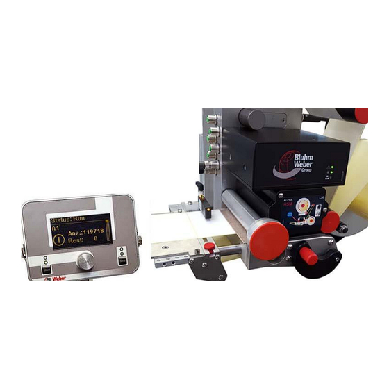
Chapter 8 Operation 40058725 BTA Alpha HSM HMI display Designations LC-DISPLAY (4-LINE) ADJUSTMENT KNOB STATUS LEDs START BUTTON STOP BUTTON Fig. 8-6: HMI display The HMI display can be used to enter data and to start and stop the labeler. The operation is menu-driven. -
Page 72: Status Leds
Chapter 8 Operation 40058725 BTA Alpha HSM Status LEDs The [Start] and [Stop] buttons each have two green control LEDs positioned above them. When the lower LED above the [Start] button is lit up, "labeling readiness" is indicated. When the upper LED flashes in addition, a trigger process has been initiated. When the upper LED is lit up, a trigger signal is pending, but the process has not been initiated. -
Page 73: Password Protection
There is a risk of damage through incorrect parametrisation. Incorrect parametrisation can lead to process and function errors that can also cause mechanical damage. - Only trained specialists and technicians from the Bluhm Weber Group are authorized to make changes. The password will be provided during training. -
Page 74: Menu Structure
Chapter 8 Operation 40058725 BTA Alpha HSM Menu structure Select the number Manual feed Temporary adjustment options (no permanent storage) Temporary speed Temp. Trigger delay Temporary label position. Configuration Service System Training Configuration Speed Counter reset PLC version Operational data... - Page 75 Chapter 8 Operation 40058725 BTA Alpha HSM The menu pages "Unwind" and "Wind" are only displayed for mod- ules with servo drive. From the menu pages "Machine parameters”,”Unwinder" and “Rewinder" you can access the submenus by pressing the setting knob briefly, which include all machine parameters of the labeler.
-
Page 76: Status Menu
Chapter 8 Operation 40058725 BTA Alpha HSM Status menu After switching on the labeler (and an initialization phase) or after prolonged input gaps (5 minutes), the display shows the "Status" menu page. The status page shows the most important status information and can at any time be reached by pressing the adjustment button for a long time (>3 seconds). -
Page 77: Manual Feed
Chapter 8 Operation 40058725 BTA Alpha HSM Manual feed The "Manual advance" menu can be reached from the status menu by turning the adjust- ment button. Here you have the possibility to dispense a label manually. This is also possible in the la- beler's stop mode. -
Page 78: Temporary Setting Options
Chapter 8 Operation 40058725 BTA Alpha HSM Temporary setting options Temporary changes to the parameters are only used to correct the settings while the dispenser is running. Permanent storage of the parameters determined must manually be performed on the "Con- figuration"... -
Page 79: Configuration Menu
Chapter 8 Operation 40058725 BTA Alpha HSM Configuration menu The configuration menu can be reached from the status menu by pressing the adjustment button for a short time and turning it in the clockwise direction. This menu includes settings for the labeler configuration that determine the progression of the application cycle. -
Page 80: Speed
Chapter 8 Operation 40058725 BTA Alpha HSM Loading a parameter set After selecting an inactive parameter set, you can load this parameter set into the control- ler and activate (allocate) (see Fig. 8-22) or delete it (see Fig. 8-23). Delete configuration? Set config? Fig. -
Page 81: Label Length
Chapter 8 Operation 40058725 BTA Alpha HSM Label Length This parameter is used to set the label length. The Label Length adjustment range is 5 – 9999 mm. With the calibration function "Teach-in" this value is determined automatically (see page86). -
Page 82: Label Skip
Chapter 8 Operation 40058725 BTA Alpha HSM Label skip The labeler can automatically recognise the posi- Label skip tion of missing labels on the carrier material and compensate for it. In the case of a gap, the label Number liner is advanced to the next available label. -
Page 83: Stop Ramp
Chapter 8 Operation 40058725 BTA Alpha HSM Stop ramp The stop ramp is set as a percentage of the ramp. Stop ramp The explanations regarding the "Ramp" parameter (Page 82) also apply for the "Stop ramp" and must therefore be considered. The adjustment range is 10-200 %. -
Page 84: Sync Length
Chapter 8 Operation 40058725 BTA Alpha HSM Sync Length This parameter is used to set the impulse length of Sync Length the Sync signal, which is provided at the I/O inter- face. If the value is set to "0", the Sync Signal will be event-driven (BUSY signal). -
Page 85: Pre Feed
Chapter 8 Operation 40058725 BTA Alpha HSM Pre Feed The pre feed position is a value that ensures that a Pre Feed label is pre-dispensed to a defined position by us- ing the "Trigger 2" (optional) input before it is finally applied to the product using the regular product detector. -
Page 86: Service Menu
Chapter 8 Operation 40058725 BTA Alpha HSM Service menu The service menu can be reached from the status menu by pressing the adjustment but- ton for a short time and turning it in the clockwise direction. This menu includes some basic settings of the labeler. Briefly press the adjustment button to get to the sub-menus. -
Page 87: Reset Lab. Counter
Chapter 8 Operation 40058725 BTA Alpha HSM Reset Lab. Counter Here you have the option of resetting the label Reset Lab. Counter counter back to "0". “ “ means to reset the counter reading, “X” maintains the counter reading. -
Page 88: Diagnosis (Io-Status)
Chapter 8 Operation 40058725 BTA Alpha HSM Diagnosis (IO-status) All of this data is purely for Diagnostics and requires a high degree of expertise for the correct interpretation. The following menu pages show current signal states of the base module. -
Page 89: System Menu
Chapter 8 Operation 40058725 BTA Alpha HSM System menu The system menu can be reached from the status menu by pressing the adjustment but- ton for a short time and turning it in clockwise direction. This menu includes some basic system settings of the labeling system. Briefly press the adjustment button to get to the sub-menus. -
Page 90: Ip Address Link
Chapter 8 Operation 40058725 BTA Alpha HSM IP address link When the *Zero-Down-Time function is used, the IP address link "Master" labeler is allocated the IP address of the "Slave" labeler. 192,168. 0,206 The input options for the IP mask are presented IP-Addr... -
Page 91: Metric / Imperial
Chapter 8 Operation 40058725 BTA Alpha HSM Metric / Imperial Here you can set the measurement units ("met- Metric / Imperial rical" or "imperial") of the labeling system. Metric Fig. 8-62: Measuring unit system Machine parameters Incorrect parametrisation can lead to process and function errors that can also cause mechanical damage. -
Page 92: Maintenance And Repair
Chapter 9 Maintenance and repair 40058725 BTA Alpha HSM 9. Maintenance and repair Safety instructions Danger through a direct or indirect contact with live parts. DANGER TO LIFE If persons come into contact with parts that have become ener- gized through malfunctions, this can lead to death. -
Page 93: Recommended Cleaning Agents
Label remover (* 21800771) Alcohol (* 21800915) or roller cleaner (* 21800977) Lint-free cloth (* 21800978) * Product recommendation! Can be obtained from the Bluhm Weber Group using the 8-digit item number. Instruction How to perform the daily maintenance/repair. Step Approach Clean the drive roller with a roller solvent on a daily basis or after changing the label roll. -
Page 94: Weekly Repair/Maintenance (After Approx. 40 Operating Hours)
Lint-free cloth (* 21800978) Compressed air spray (* 21800768) Soft brush * Product recommendation! Can be obtained from the Bluhm Weber Group using the 8-digit item number. Instruction How to perform the weekly maintenance/repair . Step Approach Clean all paper-carrying parts of adhesive deposits. To do this, use label remover or alcohol. -
Page 95: Half-Yearly Maintenance/Repair (After Approx. 1000 Operating Hours)
Chapter 9 Maintenance and repair 40058725 BTA Alpha HSM Half-yearly maintenance/repair (after approx. 1000 operating hours) Prerequisites Labeler is separated from the voltage and compressed air. No product handling. Instruction How to perform the biannual maintenance/repair. Step Approach Check that all sensors are firmly seated. -
Page 96: Cleaning Instructions
Chapter 9 Maintenance and repair 40058725 BTA Alpha HSM Cleaning instructions CLEANING AFTER CLEANING AFTER EACH EACH ROLL EXCHANGE! ROLL EXCHANGE! ORDER RECEPTION ORDER PROCESSING FRIKTIONSEINHEIT / FRICTION UNIT PRINT HEAD DESKTOP PRINTER DESKTOP PRINTER PLATEN ROLLERS SENSORS PEEL BARS... -
Page 97: Cleaning Of Sensors
Tools required Compressed air spray (* 21800768) Soft brush * Product recommendation! Can be obtained from the Bluhm Weber Group using the 8-digit item number. Instruction How to clean the light switches and sensors. Step Approach Do not use the operational compressed air supply for the subsequent clean- ings, since this is sometimes insufficiently dry (oil/water residues). -
Page 98: Cleaning Of The Deflection Rollers
Labeler is separated from the voltage and compressed air. No product handling. Tools required Label remover (* 21800771) or alcohol (* 21800915). * Product recommendation! Can be obtained from the Bluhm Weber Group using the 8-digit item number. Instruction How to clean the deflection rollers. Step Approach Manually pull out the deflection rollers. -
Page 99: Empty The Water Separator Of The Compressed Air Supply
Chapter 9 Maintenance and repair 40058725 BTA Alpha HSM Empty the water separator of the compressed air supply Damage caused by condensation water Condensation water can penetrate into the pneumatic system and damage the pneumatic components. - Check and if necessary drain the water trap regularly. -
Page 100: Spare Parts
Chapter 9 Maintenance and repair 40058725 BTA Alpha HSM Instruction How to empty the water separator. Step Approach Loosen the drain valve (pos. 6, Fig. ), until condensation of water discharges. Close the drain valve, after the collection container (pos. 5, Fig. -
Page 101: 10. Troubleshooting
Chapter 10 Troubleshooting 40058725 BTA Alpha HSM 10. Troubleshooting The chapter is divided into 2 areas, "Mechanical errors" and "Messages on the display". Instructions for performing the troubleshooting is only intended for trained profes- sionals. If the maintenance personnel cannot solve the fault, please contact our Service Hotline (see page 9). -
Page 102: Mechanical Errors
Chapter 10 Troubleshooting 40058725 BTA Alpha HSM Mechanical errors Problem Potential reason Solution Backing tape rips Label roll is damaged: Replace label roll. Indentations in the label liner. Pressure marks or dam- age to the label roll side. The paper width varies greatly. - Page 103 Chapter 10 Troubleshooting 40058725 BTA Alpha HSM Problem Potential reason Solution Web brake set too stiffly. Check the setting. With a mechanical label Newly insert the label liner as stop scanning: required or check the position Label is not correctly recog- of the label sensor.
-
Page 104: Correct The Settings After The Labeling Result
Chapter 10 Troubleshooting 40058725 BTA Alpha HSM Correct the settings after the labeling result Based on the labeling result, it is possible to draw conclusions regarding the necessary settings. Proper labeling If the labeling is performed correctly, the label will be ... - Page 105 Chapter 10 Troubleshooting 40058725 BTA Alpha HSM The label is crooked on the product. Fig. 10-3: Product with a crooked label The labeling result must be corrected as follows: Step Approach The inclination of the peeler plate could be set incorrectly. Check and correct the inclination of the peeler plate.
-
Page 106: Error And Warning Messages
Chapter 10 Troubleshooting 40058725 BTA Alpha HSM Error and warning messages As soon as there is a fault on the labeler, this is indicated immediately on the HMI display ("Error" or "Warning"). The top LED above the [Stop] button is flashing in addition. -
Page 107: Error Messages
Chapter 10 Troubleshooting 40058725 BTA Alpha HSM Error messages Motor starting fault This message implies that the internal zero-compensation could not be performed. Switch off the labeler at the mains switch and wait until the display has gone off. Thereafter, switch the labeler back on. -
Page 108: Warnings
Chapter 10 Troubleshooting 40058725 BTA Alpha HSM Warnings Initialisation phase After switching on, this message indicates the operating state of the labeler during the ini- tialization phase. Label number reached This message indicates that the "Countdown" function has run to the end and has reached the end value "000". -
Page 109: 11. Index
Chapter 11 Index 40058725 BTA Alpha HSM 11. Index Keywords from A to Z adapter module ..........37 disclosure ............7 adjustment button ..........74 display mode ........... 75 adjustments ............. 50 Donation ............ 11, 29 advance speed .......... 80, 83 drive .............. - Page 110 Chapter 11 Index 40058725 BTA Alpha HSM Label skip............85 peeling behaviour ..........53 labeling operation ..........71 PLC..............66 labeling result ..........107 PLC IP address ..........93 liability ............7, 16 pneumatics diagram ........103 light emitting diodes ......... 73 pre-dispensing ..........
- Page 111 Chapter 11 Index 40058725 BTA Alpha HSM thread ............... 56 Warning notices ..........18 threading pattern ..........56 warranty ..............7 time belts ............98 Web break ............. 110 transport............33 Web end ..........46, 111 trigger suppression .......... 85 weekly maintenance ........97 Twin Label ............
-
Page 112: 12. Declaration Of Conformity
Chapter 12 Declaration of Conformity 40058725 BTA Alpha HSM 12. Declaration of Conformity EC Declaration of Conformity , in accordance with the EC machinery directive 2006/42/EC, annex II 1. A EC DECLARATION OF CONFORMITY , according to EC Machinery Directive 2006/42/EC, Appendix II 1. A DECLARATION DE CONFORMITE CE conforme à...
Need help?
Do you have a question about the Alpha HSM and is the answer not in the manual?
Questions and answers