Table of Contents
Advertisement
Available languages
Available languages
Designed and Manufactured 100% in Italy
MANUALE DI ISTRUZIONI
ITA
Montaggio, Utilizzo & Manutenzione
INSTRUCTIONS MANUAL
ENG
Assembly, Operation & Maintenance
Istruzioni Originali / Translate of Original Instructions
Modello / Model: ASSO 950 / ACE 950
Codice / Code: 1390045 – 1390056 – 1390095
Documento / Document: DOC0103 A00
Data / Date: 28/02/2023
Chiossi e Cavazzuti s.r.l.
Via Costituzione 50/D - 42015 Correggio (RE) Italy
Tel: +39 0522 637224 - Email: support@chiossiecavazzuti.com
www.chiossiecavazzuti.com
Advertisement
Table of Contents

Related Manuals for CHIOSSI E CAVAZZUTI ASSO 950


Summary of Contents for CHIOSSI E CAVAZZUTI ASSO 950
- Page 1 Montaggio, Utilizzo & Manutenzione INSTRUCTIONS MANUAL Assembly, Operation & Maintenance Istruzioni Originali / Translate of Original Instructions Modello / Model: ASSO 950 / ACE 950 Codice / Code: 1390045 – 1390056 – 1390095 Documento / Document: DOC0103 A00 Data / Date: 28/02/2023 Chiossi e Cavazzuti s.r.l.
-
Page 3: Table Of Contents
INDICE INDICE 1.INTRODUZIONE ................................4 2. SICUREZZA ..................................6 3. DICHIARAZIONE DI CONFORMITÁ CE ..........................9 4. CARATTERISTICHE ..............................10 5. MOVIMENTAZIONE ............................... 12 6. INSTALLAZIONE ................................13 7. PANNELLO DI CONTROLLO ............................16 8. AVVIO E REGOLAZIONE PLC ............................17 9. -
Page 4: Introduzione
• I dati presenti in questo documento erano validi nel momento della pubblicazione e potrebbero cambiare senza preavviso. Chiossi e Cavazzuti srl si riserva il diritto di modificare i prodotti e cambiare le loro specifiche in ogni momento. • È vietato senza previa autorizzazione da Chiossi e Cavazzuti srl copiare, modificare, alterare, pubblicare, distribuire, vendere o trasferire questo materiale. - Page 5 1. INTRODUZIONE 1.2 ATTREZZATURA RICHIESTA Per una corretta installazione e manutenzione munirsi preventivamente della seguente attrezzatura: - avvitatore/trapano a batteria - bit a croce PH1 - bit a croce PH2 - cacciavite a lama piatta larghezza 3-5-8mm - cacciavite a croce n° 1-2 - chiave a forchetta regolabile - serie chiavi a forchetta 7-8-10-13-17-19-24-30 - serie chiavi a forchetta 7-8-10-13-17-19-24-30...
-
Page 6: Sicurezza
2. SICUREZZA 2. SICUREZZA 2.1 USO PREVISTO La macchina è concepita e costruita per una essiccazione di inchiostri all'acqua o Plastisol su indumenti e tessuti, previa verifica con il costruttore. 2.2 CONDIZIONI PREVISTE DI NON USO • La macchina è concepita e costruita per una essiccazione di inchiostri all'acqua o Plastisol su indumenti e tessuti, previa verifica con il costruttore. - Page 7 2. SICUREZZA 2.5 PRECAUZIONI PER LA SICUREZZA ELETTRICA Si raccomanda di non collegare la macchina alla rete elettrica fino a che non sia stata collocata correttamente nel luogo previsto. Prima di collegare la macchina alla rete occorre avere verificato che l’impianto elettrico di alimentazione risponda ai seguenti requisiti di sicurezza necessari.
- Page 8 3) Comunicare i dati aziendali compresi di indirizzo, P.Iva e codice SDI, nel caso non siano intercorsi rapporti commerciali negli ultimi anni con Chiossi e Cavazzuti, per velocizzare le operazioni di spedizione e fatturazione. PER COMUNICARE LE INFORMAZIONI RICHIESTE, SCRIVERE A: support@chiossiecavazzuti.com...
-
Page 9: Dichiarazione Di Conformitá Ce
3. DICHIARAZIONE DI CONFORMITA’ CE 3. DICHIARAZIONE DI CONFORMITÁ CE DICHIARAZIONE DI CONFORMITÁ CE La Ditta costruttrice: Chiossi e Cavazzuti s.r.l. Via Costituzione 50/D 42015 Correggio (RE) – Italia Dichiara che la macchina: Matricola n°: …........... Anno di fabbricazione: …........... -
Page 10: Caratteristiche
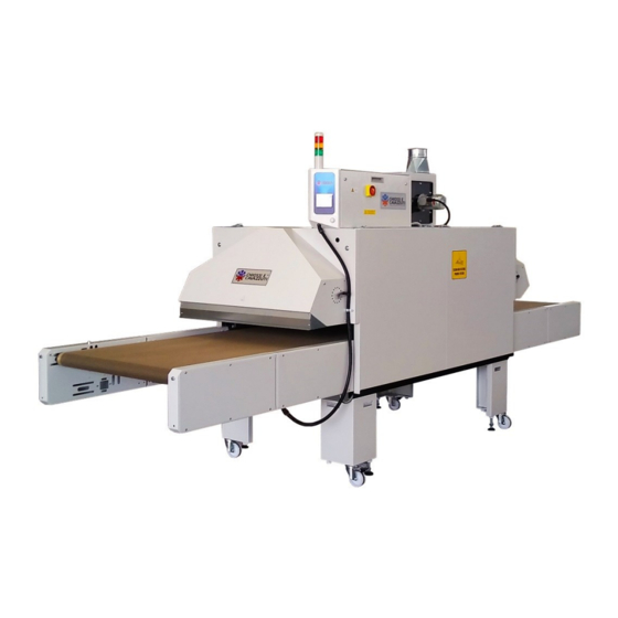
4. CARATTERISTICHE 4. CARATTERISTICHE 4.1 DESCRIZIONE E SCOPO DELLA MACCHINA “ASSO” è un forno a tunnel a elevata circolazione d’aria. È stato studiato per essiccare e polimerizzare tessuti stampati con stampanti digitali che utilizzano inchiostri a base acquosa. Non è utilizzabile con inchiostri che contengono solventi infiammabili. - Page 11 4. CARATTERISTICHE 4.4 IDENTIFICAZIONE DELLE PARTI 1) Interruttore generale 7) Manopola serranda 2) Semaforo 8) Ruota con freno 3) Nastro trasportatore 9) Apertura pannelli laterali 4) Vite centranastro 10) Uscita fumi esausti 5) Vite tensione nastro 11) Motore ventilazione 6) Ruota regolazione altezza nastro Pag.
-
Page 12: Movimentazione
5. MOVIMENTAZIONE 5. MOVIMENTAZIONE 5.1 SOLLEVAMENTO Effettuare il sollevamento con elevatore idoneo: Portata 20 quintali Lunghezza forche MAGGIORE larghezza forno. Posizionare il forno in un ambiente coperto, con una pavimentazione in piano con portata di almeno 400 Kg/mq. Mantenere una distanza dalle pareti di almeno 1 metro. Non spostare il forno su pavimenti sconnessi o cedevoli. -
Page 13: Installazione
6. INSTALLAZIONE 6. INSTALLAZIONE 6.1 COLLEGAMENTO ELETTRICO Si raccomanda di non collegare la macchina alla rete elettrica fino a che non sia stata collocata correttamente nel luogo previsto. Prima di collegare la macchina alla rete occorre avere verificato che l’impianto elettrico di alimentazione risponda ai requisiti di sicurezza necessari. - Page 14 6. INSTALLAZIONE 6.3 ALTEZZA PASSAGGIO NASTRO TRASPORTATORE Il volantino posto all’uscita del forno permette di variare la luce di passaggio. Quando il prodotto lo permette è utile tenere la minor possibile distanza tra il piano soffiante e il nastro per evitare dispersioni di calore. IMPORTANTE: non forzare il volantino di sollevamento del nastro trasportatore! Durante il trasporto il sistema di sollevamento del nastro trasportatore viene bloccato per evitare danni dovuti al libero movimento della struttura.
- Page 15 6. INSTALLAZIONE 6.5 CAPPE DI ASPIRAZIONE FUMI ESAUSTI L’aspiratore di scarico fumi si accende automaticamente quando la temperatura richiesta è prossima ad essere raggiunta in modo da rendere più rapido il riscaldamento ed evitare di sprecare energia. E’ possibile variare manualmente il flusso di fumi esausti agendo sulle serrandine e sulle valvole delle cappe di aspirazione.
-
Page 16: Pannello Di Controllo
• Assenza di fase o eventuale guasto elettrico • Assenza di raffreddamento, causata da motore ostruto o sporco • Motore difettoso o montato in modo errato. ELEMENTI DISPLAY 1) Chiossi e Cavazzuti logo (sotto menù) 2) Indicatore messaggi di Allarme 3) Ventilazione On/Off 4) Regolazione aspirazione scarico... -
Page 17: Avvio E Regolazione Plc
8. AVVIO E REGOLAZIONE PLC 8. AVVIO E REGOLAZIONE PLC Accertarsi che Il macchinario sia correttamente collegato alla linea elettrica. 8.1 ACCENSIONE DEL FORNO Ruotare l’interruttore generale giallo e rosso su ON. La spia bianca di linea si illumina confermando la presenza di tensione all’interno della cassetta elettrica. In pochi secondi segue l’accensione del display. - Page 18 Alla fine del ciclo di lavoro la macchina ha una impostazione di spegnimento automatico quando viene raggiunta la temperatura di “Auto Off” (50°C di default). Per cambiare questo parametro è necessario entrare nel sottomenù “General Options” premendo l’icona “Chiossi e Cavazzuti”. Inoltre è possibile impostare la lingua del sistema operativo tra Italiano e Inglese.
-
Page 19: Centraggio Del Nastro
9. CENTRAGGIO DEL NASTRO 9. CENTRAGGIO DEL NASTRO 9.1 OPERAZIONI PRELIMINARI Per ottenere una buona centratura del nastro è necessario innanzitutto verificare che il forno sia livellato orizzontalmente. Utilizzare i piedini di registro vicini alle ruote per correggere i disallineamenti del pavimento. Aprire i pannelli laterali e utilizzare come riferimento il telaio del forno. - Page 20 9. CENTRAGGIO DEL NASTRO 9.3 CENTRANASTRO AUTOMATICO Il centranastro automatico è a comando elettrico ed è composto di due dispositivi: un sollevatore e un tastatore. Il sollevatore agisce solo su uno dei due tubi. Il secondo tubo è da regolare manualmente regolando le viti di registro, solo al momento dell’installazione, in modo che il nastro tenda a sbandare verso il tastatore, quando il tubo movimentato è...
-
Page 21: Manutenzione E Smaltimento
10. MANUTENZIONE 10. MANUTENZIONE E SMALTIMENTO IMPORTANTE: Verificare sempre che il senso di rotazione del motore ventilanti segua la freccia rossa riportata sopra al motore. In caso contrario invertire due delle fasi di alimentazione. 10.1 PULIZIA FILTRI La principale manutenzione del forno si effettua con la pulizia dei filtri di cui è dotato. Procedere con qualsiasi intervento di manutenzione solo a macchinario spento e a temperatura ambiente. -
Page 22: Utilizzo E Dismissione
11. UTILIZZO E DISMISSIONE 11. UTILIZZO E DISMISSIONE 11.1 UTILIZZO E POSIZIONE DI LAVORO Prima di attivare qualunque operazione con la macchina, accertarsi che intorno all'area di lavoro non siano presenti persone o altri ostacoli che potrebbero essere fonte di pericolo. •... - Page 23 Montaggio, Utilizzo & Manutenzione INSTRUCTIONS MANUAL Assembly, Operation & Maintenance Istruzioni Originali / Translate of Original Instructions Modello / Model: ASSO 950 / ACE 950 Codice / Code: 1390045 – 1390056 – 1390095 Documento / Document: DOC0103 A00 Data / Date: 28/02/2023 Chiossi e Cavazzuti s.r.l.
-
Page 25: Index
INDEX INDICE 1.INTRODUZIONE ................................4 2. SICUREZZA ..................................6 3. DICHIARAZIONE DI CONFORMITÁ CE ..........................9 4. CARATTERISTICHE ..............................10 5. MOVIMENTAZIONE ............................... 12 6. INSTALLAZIONE ................................13 7. PANNELLO DI CONTROLLO ............................16 8. AVVIO E REGOLAZIONE PLC ............................17 9. -
Page 26: Introduction
1. INTRODUCTION 1. INTRODUCTION Dear Customer, Congratulations on your choice. In so doing you have joined a long list of other customers of Chiossi and Cavazzuti products. With this equipment you will be able to obtain results of the highest quality. To this end and before using the machine we invite you to carefully read this instruction manual. - Page 27 1. INTRODUCTION 1.2 EQUIPMENT REQUIRED To properly install and maintain the Dryer you will need this equipment in advance: - cordless screwdriver/drill - Phillips bit PH1 - Phillips bit PH2 - flat-blade screwdrivers width 3-5-8 mm - Phillips screwdrivers n ° 1-2 - adjustable spanner wrench - fork spanner set 7-8-10-13-17-19-24-30 - tube spanner set 7-8-10...
-
Page 28: Safety
2.SAFETY 2. SAFETY 2.1 INTENDED USE • The machine is designed and built for drying water-based inks or Plastisol on clothing and fabrics, subject to verification with the manufacturer. 2.2 PROVIDED CONDITIONS OF NON-USE • The end user is responsible for damage caused by use other than that specified in this manual and with materials other than those for which the machine has been designed. - Page 29 2.SAFETY 2.5 PRECAUTIONS FOR ELECTRICAL SAFETY It is recommended not to connect the machine to the power supply until it has been correctly placed in the intended place. Before connecting the machine to the network, make sure that the electrical system meets the following safety requirements.
- Page 30 2.SAFETY 2.10 RISK DUE TO SOUND EMISSIONS The machine is designed and built so as to reduce the sound emission level at the source. The sound power level of the machine is less than 70 dB (A) and is well tolerated by the operator and by the people close to him.
-
Page 31: Ce Declaration Of Conformity
3. CE DECLARATION OF CONFORMITY 3. CE DECLARATION OF CONFORMITY CE DECLARATION OF CONFORMITY The Manufacturer: Chiossi e Cavazzuti s.r.l. Via Costituzione 50/D 42015 Correggio (RE) – ITALY Declares that the machine: Serial No............Manufacturing Year: ............Trade name: “ACE 950”... -
Page 32: Features
4. FEATURES 4. FEATURES 4.1 DESCRIPTION AND PURPOSE OF THE MACHINE “ACE” is an elevated circulation hot air tunnel dryer. It has been designed to dry and polymerize fabrics printed with digital printers using water based inks. Do not use with inks containing flammable solvents. Electric heating was chosen because it involves fewer installation and maintenance problems. - Page 33 4. FEATURES 4.4 PARTS IDENTIFICATION 1) Main Switch 7) Shutter knob 2) Indicator lights 8) Caster with brake 3) Belt conveyor 9) Panel blocking hooks 4) Belt centering screw 10) Exhaust fumes extractor 5) Belt tensioning screw 11) Ventilation motor 6) Conveyor belt raising wheel Pag.
-
Page 34: Handling
5. HANDLING 5. HANDLING 5.1 LIFTING The lifting must be carried out with a suitable forklift: Capacity 20 quintals Forks Length GREATER than Dryer Width. Place the Dryer in a covered area, with a floor covering with a capacity of at least 400 Kg/sqm and keep a distance of at least 1 meter from walls. -
Page 35: Installation
6. INSTALLATION 6. INSTALLATION 6.1 ELECTRICAL CONNECTION It is recommended not to connect the machine to the power supply until it has been correctly placed in its final position. Before connecting the machine to the power line, make sure that the electrical system meets the following safety requirements. - Page 36 6. INSTALLATION 6.3 LIFTING BELT HANDWHEEL The handwheel at the output of the machine is used to adjust the height of the belt conveyor. Where permitted by the product it is useful to keep the passage distance between the blowers and the conveyor belt as small as possible. This causes the air speed to be at a maximum.
- Page 37 6. INSTALLATION 6.5 EXHAUST FUMES FLOW The fumes extraction ventilator fan starts automatically when the set temperature is about to be reached. This means that heating is more rapid and less energy is wasted. The exhaust fumes ventilation can be adjusted manually moving the shutter and the sunction lever on the extraction hoods.
-
Page 38: Control Panel
• Electrical failure (missing phase, wrong motor direction) • Cooling failure, produced by dirt in the motor • Defective or poorly installed motor 7.2 DISPLAY ELEMENTS 1) Chiossi e Cavazzuti logo (hidden menu) 2) Alarm indicator 3) Ventilation On/Off icon... -
Page 39: Start Up And Plc Adjustmen
8. START UP AND PLC ADJUSTMEN 8. START UP AND PLC ADJUSTMEN Make sure the machine is properly connected to the electrical line. 8.1 TURN ON THE DRYER Turn the main power switch ON. The white voltage indicator will turn on, confirming the presence of voltage inside the electrical cabinet. Within seconds follows the boot of the display. - Page 40 At the end of the working cycle the machine has an automatic turning Off feature when the “Auto Off” temperature is reached (50°C by default). To change this parameter it is necessary to enter the “General Options” menu, pressing the “Chiossi e Cavazzuti-shaped” icon. Furthermore it is possible to change the language between Italian and English.
-
Page 41: Belt Centering
9. BELT CENTERING 9. BELT CENTERING 9.1 PRELIMINARY OPERATIONS In order to obtain a precise belt centering, the first thing to do is to verify that the dryer is on level. Use the leveling feet near the casters to correct any unevenness to the floor. Open the lateral panels and use the frame of the dryer as a reference. - Page 42 9. BELT CENTERING 9.3 AUTOMATIC BELT CENTERING The automatic belt centering system is electrically controlled and comprises two devices: a lifter and touch sensor. The lifter acts only upon one of the two tubes. At installation the second tube needs to be manually adjusted such that the belt tends to veer towards the side where the touch sensor is installed and when the tube has been moved downwards (4).
-
Page 43: Maintenance
10. MAINTENANCE 10. MAINTENANCE IMPORTANT: Always verify that the sense of rotation of the ventilation motors follows the red arrow on top. If not, switch two of the main phases. 10.1 CLEANING THE FILTERS The main maintenance of the dryer is carried out by cleaning the filters it is equipped with. Proceed with any maintenance operation only if the machine is switched off and it is at room temperature. -
Page 44: Usage And Dismission
11 USAGE AND DISMISSION 11. USAGE AND DISMISSION 11.1 USAGE AND WORKING POSITION Before activating any operation with the machine, make sure that there are no people or other obstacles around the work area that could be a source of danger.? Check that the work area is well lit and that the deposit of the material to be processed and the one worked is handy and well ordered. -
Page 45: Disegni
12. DISEGNI / DRRAWINGS 12. DISEGNI DRAWINGS Pag. 45 a 47 28/02/2023 Nome file: DOC0103 A00... - Page 46 12. DISEGNI / DRRAWINGS Pag. 46 a 47 28/02/2023 Nome file: DOC0103 A00...
- Page 47 12. DISEGNI / DRRAWINGS Pag. 47 a 47 28/02/2023 Nome file: DOC0103 A00...
Need help?
Do you have a question about the ASSO 950 and is the answer not in the manual?
Questions and answers