Advertisement
1 0 5 . 4 4 5
A l a r m
Please Note
The OPITEC range of projects is not intended
as play toys for young children.They are tea-
ching aids for young people learning the skills
of Craft, Design and Technolo- gy.These pro-
jects should only be undertaken and tested
with the guidance of a fully qualified adult. The
finished projects are not suitable to give to
children under 3 years old. Some parts can be
swallowed. Dan- ger of suffocation!
1
E105445#1
Advertisement
Table of Contents

Related Manuals for Opitec 105.445

Summary of Contents for Opitec 105.445
- Page 1 1 0 5 . 4 4 5 A l a r m Please Note The OPITEC range of projects is not intended as play toys for young children.They are tea- ching aids for young people learning the skills of Craft, Design and Technolo- gy.These pro- jects should only be undertaken and tested with the guidance of a fully qualified adult.
-
Page 2: Material Information
1. Product information: Article: Battery operated circuit Use: in Design Technology Key Stage 3 2. Material information 2.1. Material: Pine (coniferous) softwood Wood should be realtively dry before working Gabun plywood, multi layered Working: All wood can be sawn, filed, drilled and sanded Measure to size or use a pattern Joining: Use PVA white woodworking glue;... - Page 3 3. Tools Drilling: Use a handrill or a pillar drill Note! Take care when drilling and adhere to the safety rules, tie all long hair back, remove rings and jewellery. Hold work to be drilled in a vice Cutting: Use side cutters for cutting the insulated wire and brass strip Soldering: For soldering use a 15-30 Watt iron with a fine tip and a flux paste Note:...
-
Page 4: Exploded Diagram
5. Exploded diagram: Scale 1 : 2 6. Wiring diagram Buzzer Battery 1,5V Clothes peg D105434#1... - Page 5 7. Planning and Making 7.1 Planning and making the case 7.2 Making the trip wire 7.3 Designing the switch (Clothes peg and Brass strip) 7.4 Mounting the components 7.1 Planning and making the case 7.1.1 Drill the base (1a) and the cover (1b) as shown in the diagram (see page 9) Note: The dotted line on the base shows the position of the circuit Cover (1b)
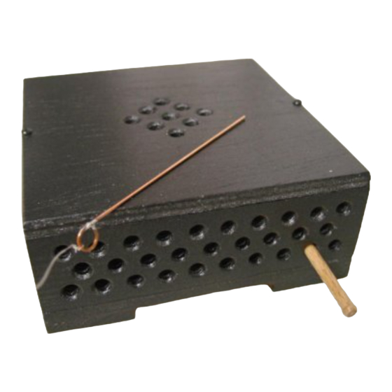
- Page 6 7.1.3 Finally mark out and drill the side (2c) as shown in the diagram (see page 5) Note. The number of holes in the side make it difficult for the alarm to be ‘cracked’ and at the same time you can hear the ‘noise’ better. 7.1.4 Glue the feet in the corners of the frame Note: Make sure the case is made properly so that that the dowel can be inserted into a hole and...
-
Page 7: Mounting The Components
7.3 Designing the switch (clothes peg and brass strip) 7.3.1Cut two pieces, each 35m long from the brass strip and bend them around the ends of the clothes peg. (see diagram) 7.3.2 Solder a formed brass contact to the minus pole( Black cable) on the pulse tone alarm. - Page 8 7.4.3 Testing and Evaluating the circuit Insert the dowel into the corrct hole in the side of the case and in between the contacts on the clothes peg. Now set up the trip wire. When the dowel is pulled out of the box the contacts on the clothes peg close, making the circuit and setting off the alarm.
- Page 9 Patterns 107,5 M 1 : 1 Cover (1b) Ø 5 Ø 2 Ø 2 Base (1a) Ø 3 Ø 3 Ø 3 E105445#1...
Need help?
Do you have a question about the 105.445 and is the answer not in the manual?
Questions and answers