Table of Contents
Advertisement
Quick Links
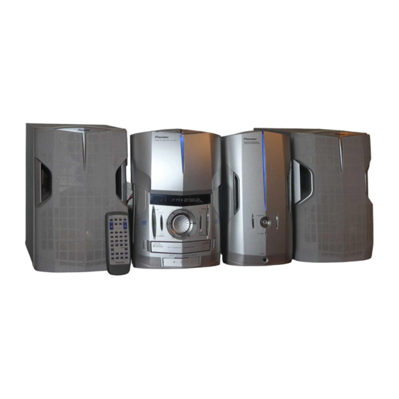
CD/VCD TUNER DECK
XC-IS22VCD
THIS MANUAL IS APPLICABLE TO THE FOLLOWING MODEL(S) AND TYPE(S).
Model
Type
XC-IS22VCD
ZBDXJ
O
ZLXJ/NC
O
This product is a system(s) component.
This product does not function properly when independent; to avoid malfunctions, be sure
to connect it to the prescribed system component(s), otherwise damage may result.
Component
CD/VCD TUNER DECK
DVD TUNER DECK
STEREO POWER AMPLIFIER
SPEAKER SYSTEM
CONTENTS
1. SAFETY INFORMATION ....................................... 2
2. EXPLODED VIEWS AND PARTS LIST ................. 3
4. PCB CONNECTION DIAGRAM ........................... 34
5. PCB PARTS LIST ................................................ 46
6. ADJUSTMENT ..................................................... 51
7. GENERAL INFORMATION .................................. 57
PIONEER ELECTRONIC CORPORATION
PIONEER ELECTRONICS SERVICE, INC. P.O. Box 1760, Long Beach, CA 90801-1760, U.S.A.
PIONEER ELECTRONIC NV Haven 1087, Keetberglaan 1, 9120 Melsele, Belgium
PIONEER ELECTRONICS ASIACENTRE PTE. LTD. 253 Alexandra Road, #04-01, Singapore 159936
c
PIONEER ELECTRONIC CORPORATION 2001
Power Requirement
DC power supply from other system
DC power supply from other system
System
XC-IS22VCD
XV-IS22DVD
M-IS22
S-IS22
4-1, Meguro 1-chome, Meguro-ku, Tokyo 153-8654, Japan
OPEN/
CLOSE
STEREO CD/VCD TUNER DECK
XC-IS22VCD
CD
TAPE
ENHANCE
FOLDER/TRACK
BASS
TREBLE
TUNER
LINE1.2
Service Manual
RRV2477
RRV2475
RRV2482
RRV2461, RRV2487
7.1 DIAGNOSIS ................................................... 57
7.1.2 SINGLE OPERATION METHOD ........... 58
7.1.3 TROUBLE SHOOTING .......................... 60
7.1.4 DISASSEMBLY ..................................... 61
7.2 PARTS .......................................................... 66
7.2.1 IC ........................................................... 66
8. PANEL FACILITIES AND SPECIFICATIONS ....... 78
ORDER NO.
RRV2477
Remarks
Remarks
This service manual
T - ZZY JUNE 2001 Printed in Japan
Advertisement
Table of Contents

Related Manuals for Pioneer XC-IS22VCD


Summary of Contents for Pioneer XC-IS22VCD
-
Page 1: Table Of Contents
PIONEER ELECTRONIC CORPORATION 4-1, Meguro 1-chome, Meguro-ku, Tokyo 153-8654, Japan PIONEER ELECTRONICS SERVICE, INC. P.O. Box 1760, Long Beach, CA 90801-1760, U.S.A. PIONEER ELECTRONIC NV Haven 1087, Keetberglaan 1, 9120 Melsele, Belgium PIONEER ELECTRONICS ASIACENTRE PTE. LTD. 253 Alexandra Road, #04-01, Singapore 159936 PIONEER ELECTRONIC CORPORATION 2001 T –... -
Page 2: Safety Information
If you are not qualified to perform the repair of this product properly and safely, you should not risk trying to do so and refer the repair to a qualified service technician. IMPORTANT THIS PIONEER APPARATUS CONTAINS LASER DIODE CHARACTERISTICS LASER OF CLASS 1. -
Page 3: Exploded Views And Parts List
Packing Case M See Contrast table (2) Battery Cover XZN3116 Power Plug Adapter See Contrast table (2) (2) CONTRAST TABLE XC-IS22VCD/ZBDXJ and XC-IS22VCD/ZLXJ/NC are constructed the same except for the following: Part No. Symbol and Description Mark Remarks ZBDXJ type ZLXJ/NC type... - Page 4 XC-IS22VCD 2.2 EXTERIOR Refer to "2.4, 2.5 DECK MECHANISM UNIT (1/2 and 2/2)".
- Page 5 PPZ30P080FMC Screw VPZ30P080FZK Cord Clamper (steel) RNH-184 Screw BBZ30P080FZK Spacer XEB3023 (2) CONTRAST TABLE XC-IS22VCD/ZBDXJ and C-IS22VCD/ZLXJ/NC are constructed the same except for the following: Part No. Symbol and Description Mark Remarks ZBDJ type ZLXJ/NC type Name Label XAL3080 XAL3081...
- Page 6 XC-IS22VCD 2.3 FRONT PANEL ASSY...
- Page 7 XC-IS22VCD ÷ FRONT PANEL ASSY PARTS LIST Mark No. Description Parts No. FRONT PANEL ASSY XWZ3408 F-TERMINAL ASSY XWZ3487 CD OPEN SW ASSY XWZ3411 CD CLOSE SW ASSY XWZ3412 LIGHT- L ASSY XWZ3413 LIGHT- R ASSY XWZ3414 MEDIA BLUE LED ASSY...
- Page 8 XC-IS22VCD 2.4 DECK MECHANISM UNIT (1/2) Refer to "2.5 DECK MECHANISM UNIT (2/2)".
- Page 9 XC-IS22VCD ÷ DECK MECHANISM UNIT (1/2) PARTS LIST Mark No. Description Parts No. Screw FG114-14 Screw UG12H-15 Front BKT FC64K-11 Washer MJ112-22 SP Return FK34N-11 Plate Hold BLK F573-258 Holder CST BLK F527-078 LDG Base FD56R-12 Pulley FD56T-11 LDG Gear...
- Page 10 XC-IS22VCD 2.5 DECK MECHANISM UNIT (2/2)
- Page 11 XC-IS22VCD ÷ DECK MECHANISM UNIT (2/2) PARTS LIST Mark No. Description Parts No. Screw KG194-36 Reel Feather FD57D-13 Screw UG11S-14 SP Reel(L) FK32U-12 SP Brake FK33B-13 SP Arm Play FK33P-11 SP Reel(R) FK32V-12 Spring Cassette FC65M-11 BKT MTR FC64M-12 Reel Base...
-
Page 12: Block Diagram And Schematic Diagram
XC-IS22VCD 3. BLOCK DIAGRAM AND SCHEMATIC DIAGRAM 3.1 BLOCK DIAGRAM CN1201 CN5505 (CD) (CD) (CD) (CD) (CD) (CD) (CD) CD ASSY FM/AM TUNER MODULE CN5501 CN3004 (CD) CN52 CN5504 (TX) (TX) CN5502 CN3003 TOUCH ASSY FRONT PANEL CN101 CN101 ASSY... - Page 13 XC-IS22VCD DECK ASSY (PB) (PB) F-TERMINAL ASSY (REC) SIGNAL ROUTE (PB) : PB SIGNAL (REC) : RECORDING SIGNAL (TX) : AUDIO SIGNAL (TUNER) (CD) (L2) : CD SIGNAL (L2) (L1) : RF SIGNAL : LINE 1 SIGNAL (L2) : LINE 2 SIGNAL...
- Page 14 XC-IS22VCD 3.2 OVERALL CONNECTION DIAGRAM CD MECHA ASSY (KSM-900AAA) CN5505 - 3/3 CN5502 CD ASSY (XWP3002) CN3003 CN1201 S2B-PH-SM3 CN1302 AF ASSY (XWZ3464) CN8001 CN2701 DECK ASSY (XWX3038) CN2202 CN103...
- Page 15 XC-IS22VCD Note : When ordering service parts, be sure to refer to "EXPLODED VIEWS and PARTS LIST" or "PCB PARTS LIST". FM/AM TUNER MODULE (AXQ7228) CN201 CN5509 CN5503 LIGHT-R ASSY (XWZ3414) CN50 IF ASSY (XWZ3465) CN5506 CN5507 CN51 LIGHT-L ASSY...
- Page 16 XC-IS22VCD 3.3 FM/AM TUNER MODULE FM/AM TUNER MODULE (AXQ7228) FM FRONT END (FM) (FM) (FM) (FM) (FM) (AM) (AM) (AM) MW RF TUNING BLOCK (FM) (AM) OSC : 981 - 2052kHz 9k step...
- Page 17 XC-IS22VCD : The power supply is shown with the marked box. (TX) : AUDIO SIGNAL ROUTE (TUNER) (AM) : AM SIGNAL ROUTE (FM) : FM SIGNAL ROUTE (AM) (TX) (FM) (TX) (TX) CN201 (TX) (FM) (FM) (TX) (AM) L201 ATE7003...
- Page 18 XC-IS22VCD 3.4 IF ASSY IF ASSY (XWZ3465) CN201 CN5501 (CD) (CD) (CD) (TX) CN5502 CN5504 CN52...
- Page 19 XC-IS22VCD VIDEO OUT : The power supply is shown with the marked box. JA5001 L5652 VTL1084 CN5505 (CD) (CD) (CD) CN5506 CN5507 CN5509 SIGNAL ROUTE (CD) : CD AUDIO SIGNAL ROUTE (TX) : AUDIO SIGNAL ROUTE (TUNER) : DIGITAL SIGNAL ROUTE...
- Page 20 XC-IS22VCD 3.5 AF and MIDIA BLUE LED ASSYS (LO1) (LO1) (L2) (L1) (LO2) (LO2) (MIC) (MIC) (L1) (MO) (MO) (L1) (MO) CN3006 (PB) (PB) (REC) (REC) CN3008 CN8001 TOUCH ASSY (TX) CN3004 CN5501...
- Page 21 XC-IS22VCD CN103 : The power supply is shown with the marked box. AF ASSY (XWZ3464) CN3005 MAIN MIC BA4558F (L2) (MIC) (MIC) (MIC) (LO2) (MO) BA4558F (L2) (L2) (MIC) (MIC) (LO2) (MO) (MIC) SIGNAL ROUTE (LO2) : LINE OUT 2 SIGNAL...
- Page 22 XC-IS22VCD 3.6 DECK ASSY DECK ASSY (XWX3038) (PB) CN2301 (PB) CN2302 (REC) (PB) (REC) (REC) (REC) SIGNAL ROUTE (PB) : PB SIGNAL (REC) : RECORDING SIGNAL...
- Page 23 XC-IS22VCD : The power supply is shown with the marked box. J2201 (PB) (PB) CN2202 (PB) (PB) (REC) (REC) CN2701 CN2603...
- Page 24 XC-IS22VCD 3.7 CD (1/3) and CD MOTOR ASSYS CD ASSY (XWP3002) 6.7V (SM) CD MOTOR ASSY (XWZ3410) (FS) (FS) (FS) (SM) (FS) (SM) (TS) (SM) (TS) (CM) (LM) (CM) (LM) (TS) (CM) (CM) (FS) CN11 (TS) (TS) (FS) Note: The encircled numbers denote measuring point in the schematic diagram.
- Page 25 XC-IS22VCD (CD) (FS) (TS) (CD) 2.44V (TS) (TS) (FS) (CM) (SM) (CD) (CD) SIGNAL ROUTE (CD) : CD AUDIO SIGNAL ROUTE : DIGITAL SIGNAL ROUTE (SM) : RF SIGNAL ROUTE : SPINDLE MOTOR ROUTE (FS) (CM) : FOCUS SERVO LOOP LINE...
- Page 26 XC-IS22VCD 3.8 CD (2/3) ASSY CD ASSY (XWP3002)
- Page 27 XC-IS22VCD : The power supply is shown with the marked box. CN1501 (MP3) SIGNAL ROUTE (MP3) : MP3 SIGNAL ROUTE (MP3) (MP3)
- Page 28 XC-IS22VCD 3.9 CD (3/3) ASSY CD ASSY (XWP3002) (CD) (CD) (CD) (CD)
- Page 29 XC-IS22VCD : The power supply is shown with the marked box. SIGNAL ROUTE (CD) : CD AUDIO SIGNAL ROUTE (CD) : DIGITAL SIGNAL ROUTE : VIDEO SIGNAL ROUTE (MP3) : MP3 SIGNAL ROUTE 4.89V 3.35V CN1201 (CD) (CD) (CD) (CD)
- Page 30 XC-IS22VCD 3.10 F-TERMINAL ASSY F-TERMINAL ASSY (XWZ3487)
- Page 31 XC-IS22VCD SIGNAL ROUTE (L2) : LINE 2 SIGNAL : The power supply is shown with the marked box. (LO2) : LINE OUT 2 SIGNAL (L2) (L2) (LO2) CN103 CN49 CN3005...
- Page 32 XC-IS22VCD 3.11 FRONT PANEL, LIGHT-L, LIGHT-R, CD OPEN SW and CD CLOSE SW ASSYS CN5504 CN52 CN50 LIGHT-R ASSY (XWZ3414) CN51 LIGHT-L ASSY (XWZ3413) I J K...
- Page 33 XC-IS22VCD : The power supply is shown with the marked box. FRONT PANEL ASSY (XWZ3408) S5901: VCD/CD S5902: TUNER S5903: BASS S5905: - S5906: DISP S5907: ENHANCE S5908: TAPE S5909: LINE 1, 2 S5910: TREBLE S5911: FOLDER/TRACK S5912: SET S5913: +...
-
Page 34: Pcb Connection Diagram
XC-IS22VCD 4. PCB CONNECTION DIAGRAM NOTE FOR PCB DIAGRAMS : 1. Part numbers in PCB diagrams match those in the schematic 3. The parts mounted on this PCB include all necessary parts for diagrams. several destinations. 2. A comparison between the main parts of PCB and schematic For further information for respective destinations, be sure to diagrams is shown below. - Page 35 XC-IS22VCD 4.1 TUNER MODULE SIDE A FM/AM TUNER MODULE CN5503 (ANP7338-B) Q202 SIDE B FM/AM TUNER MODULE (ANP7338-B) Q201 IC201 Q203 Q205 IC202 Q204...
- Page 36 XC-IS22VCD 4.2 IF ASSY SIDE A LCD ASSY IF ASSY CN201 CN52 (XNP3038-B) CN1201 CN3004 CN3003 J2202...
- Page 37 XC-IS22VCD SIDE B IF ASSY (XNP3038-B) Q5505 IC5501 Q5508 Q5504 Q5501 Q5502 Q5506 Q5751 Q5503 Q5507 Q5752 IC5502...
- Page 38 XC-IS22VCD 4.3 AF and MEDIA BLUE LED ASSYS AF ASSY J2201 J103 (XNP3038-B) IC3901 IC3004 IC3001 IC3003 SIDE A IC3002 Q3004 Q4001 Q305 IC301 Q304 CN5501 IC131 Q131 CN5502 Q141 MEDIA BLUE Q2001 Q306 IC141 LED ASSY...
- Page 39 XC-IS22VCD AF ASSY Q3005 IC7301 Q7301 (XNP3038-B) Q3006 Q3011 IC3001 IC3004 IC3901 IC3003 IC3002 SIDE B Q3003 Q3002 Q3001 Q3010 Q3013 Q3009 MEDIA BLUE Q4002 Q3015 Q3014 Q301 Q302 LED ASSY...
- Page 40 XC-IS22VCD 4.4 DECK ASSY DECK ASSY CN3006 DECK MECHA (XNP3039-C) Q2702 Q2701 Q2708 Q2805 Q2301 Q2801 Q2802 Q2803 Q2806 Q2802 VR2302 Q2704 Q2703 VR2701 VR2801 VR2802 VR2401 VR2402 CN5506 DECK MECHA DECK MECHA DECK MECHA SIDE A...
- Page 41 XC-IS22VCD Q2305 IC2301 Q2303 Q2306 Q2304 Q2401 (XNP3039-C) Q2402 Q2452 Q2451 IC2401 IC2201 Q2254 Q2253 Q2251 IC2202 Q2262 Q2261 Q2263 Q2351 Q2201 Q2252 Q2602 Q2603 IC2601 Q2707 Q2709 Q2705 Q2711 Q2710 Q2706 SIDE B...
- Page 42 XC-IS22VCD 4.5 CD and CD MOTOR ASSYS SIDE A CD ASSY CD MECHANISM ASSY IC1751 IC1776 IC1771 (XNP3046-C)
- Page 43 XC-IS22VCD SIDE B CD ASSY CD MOTOR ASSY Q1102 IC1201 IC1801 IC1202 IC1101 IC1851 Q1101 IC1301 Q1302 IC1701 IC1501 IC1756 Q1701 Q1551 IC1451 IC1401 IC1551 Q1432 Q1431 Q1434 IC1441 Q1433 (XNP3046-B) CN5505...
- Page 44 XC-IS22VCD 4.6 FRONT TERMINAL, FRONT PANEL, LIGHT-L, LIGHT-R, CD CLOSE SW and CD OPEN SW ASSYS CD CLOSE SW ASSY SIDE A LIGHT-L ASSY FRONT PANEL ASSY (XNP3038-B) FRONT TERMINAL (XNP3038-B) ASSY (XNP3038-B) CD OPEN SW ASSY CN3005 (XNP3038-B) CN5504...
- Page 45 XC-IS22VCD SIDE B LIGHT-L ASSY FRONT PANEL ASSY (XNP3038-B) FRONT TERMINAL ASSY (XNP3038-B) (XNP3038-B) Q5902 Q5901 Q5905 Q5904 Q5903 (XNP3038-B) LIGHT-R ASSY...
-
Page 46: Pcb Parts List
XC-IS22VCD 5. PCB PARTS LIST • NOTES: Parts marked by "NSP" are generally unavailable because they are not in our Master Spare Parts List. • mark found on some component parts indicates the importance of the safety factor of the part. - Page 47 XC-IS22VCD Mark No. Description Part No. Mark No. Description Part No. Q3014 DTC124EK IF ASSY D3006 1SS133 D141, D3011, D3013, D3016, D302 1SS355 SEMICONDUCTORS D3049, D7301-D7304 1SS355 IC5501 PDC075B D3004 MTZJ10C Q5501, Q5504 2SC2412K Q5503, Q5506, Q5507 DTC143EK D304 S5688G...
- Page 48 XC-IS22VCD Mark No. Description Part No. Mark No. Description Part No. C 2221,C 2222,C 2261,C 2262 CEAT4R7M50 MEDIA BLUE LED ASSY C 2419,C 2420 CEAT4R7M50 C 2205,C 2206 CEATR22M50 SEMICONDUCTORS C 2252 CKSQYB105K10 C 2702 CKSQYB474K16 Q 8001 2SC2412K D 8003-D 8006...
- Page 49 XC-IS22VCD Mark No. Description Part No. Mark No. Description Part No. Q1102 DTC124TKA RESISTORS D1431, D1432 DAN202K R1540, R1819, R1820 RAB4C0R0J D1301 UDZ2.0B R1219, R1520 RAB4C221J R1546, R1813-R1816 RAB4C473J COILS ANDFILTERS R1318 RS1/16S1202F L1712 LCTB1R8K2125 R1319 RS1/16S2202F L1711 LCTB2R7K2125 L1102, L1202, L1206...
- Page 50 XC-IS22VCD Mark No. Description Part No. FRONT PANEL ASSY SEMICONDUCTORS Q 5901,Q 5903-Q 5905 2SC2412K Q 5902 DTA124EK D 5902-D 5905 1SS133 SWITCHES S 5901-S 5920 ASG7013 S 5921 ASX7026 RESISTORS R 5934 RD1/4PU101J Other Resistors RS1/16S&&& J OTHERS 54,55...
-
Page 51: Adjustment
XC-IS22VCD 6. ADJUSTMENT For adjustment, use the stereo power amplifier (M-IS21). 6.1 DECK SECTION 6.1.1 Adjustment Condition 7 List of Adjustments (1) The ground at the time of adjustment shall be W166. ¶ Playback Section (Refer to Fig. 6–3). (2) Clean the heads and demagnetize them using a head eraser. - Page 52 XC-IS22VCD 6.1.2 Playback Section (1) Tape Speed Confirmation Mode Input Signal/Test Tape Adjustment Points Measurement Points Adjustment Value Remarks FWD adjustment VR2701 (DECK ASSY) TP R (C2204) 3000 Hz PLAY NCT-111 (3 kHz) REV Confirmation –10 (Refer to Fig. 6-3)
- Page 53 XC-IS22VCD DECK ASSY SIDE A C2203 (TP Lch) VR2301 (Lch) PB LEVEL C2204 (TP Rch) W166 VR2302 (TP GND) (Rch) REC LEVEL VR2401 VR2402 (Lch) (Rch) TAPE SPEED BIAS VR2701 VR2801 VR2802 (Lch) (Rch) MECHANISM UNIT REV Azimuth FWD Azimuth...
- Page 54 XC-IS22VCD 6.2 CD SECTION Note : There is no information to be shown in this CD adjustment. 6.2.1 HOW TO START / CANCEL TEST MODE TEST MODE : ON TEST MODE W323 W323 Short circuit Release TX TEST W324 W324...
- Page 55 XC-IS22VCD FUNCTION OF CD TEST MODE OPEN/CLOSE TOUCH SENSOR OPEN/ CLOSE CD cover Open / Close STEREO CD/VCD TUNER DECK XC-IS22VCD DISPLAY Laser diode: LIGHT UP Focus servo: ON TAPE ENHANCE FOLDER/TRACK Carriage OUT Carriage IN BASS TREBLE TUNER LINE1.2...
- Page 56 XC-IS22VCD 6.3 TUNER SECTION 6.3.1 AM TUNER SECTION There is no adjustment in the AM tuner. 6.3.2 FM TUNER SECTION Set the mode selector to FM BAND. Connect the wiring as shown in Fig. 6-5. ANT. Input level and signal condition...
-
Page 57: General Information
XC-IS22VCD 7. GENERAL INFORMATION 7.1 DIAGNOSIS 7.1.1 SEQUENCE AFTER THE POWER ON Note 1 : IC No. or P∗∗ without name indicate the pin No. Note ; ∗1 : System bus communication of microcomputer (IC5501). P8 SCLK P9 SDATA P10 SREQ Standby states ∗2 : Starts the LCD communication... -
Page 58: Single Operation Method
XC-IS22CD 7.1.2 SINGLE OPERATION METHOD Single purpose operation test mode specification for IS22CD service. Jigs and Measuring instruments DC power- supply Single purpose operation method. 1 Connect point A of the AF ASSY [+8V, +15V, GND] and DC power-supply. (Refer to Fig. 7-1.) DC power-supply Connect point A Voltage (V) - Page 59 XC-IS22CD CONNECTED POINT AF ASSY Rear +5.6V +15V SIDE B STEP 1 OPEN/ CLOSE Fig. 7-1 STEREO CD/VCD TUNER DECK XC-IS22VCD +15V TAPE ENHANCE FOLDER/TRACK BASS TREBLE STEP 2 TUNER LINE1.2 BASS TREBLE 5.6V BASS TREBLE Fig. 7-2...
-
Page 60: Trouble Shooting
XC-IS22VCD 7.1.3 TROUBLE SHOOTING XC-IS22CD microcomputer trouble shooting. " " r i f r i f " . " g i l r i f r i f l l i l l i l l i l l i . -
Page 61: Disassembly
XC-IS22VCD 7.1.4 DISASSEMBLY Note: The disassembly is the same although this photograph is XC-IS22VCD. Note : Flexible cables are not removed in the case of the adjustment, but remove Front Panel Assy the Flexible cables to apply in the case of the exchange or repair. - Page 62 XC-IS22VCD CD Mechanism Assy CD Assy Binder CD Assy ×3 ×3 Binder Remove the Rail L Rail L Earth Lead Wire CD Door Block Remove the CD Door Block Rail R Remove the Rail R Each Wire rod is Removed.
- Page 63 XC-IS22VCD CD Door Drive Block CD Door CD MechanismAssy CD Assy Remove the CD Door CD Door Drive Block Caution : When the CD Assy is pulled out, be careful not to break Flexible Cable. CD Assy ×4 Exchange Exchange...
- Page 64 XC-IS22VCD Deck Mechanism Unit Remove the Front panel Assy (Refer to Front panel Assy) DECK Mechanism Unit AF Assy Slide Exchange, Repair DECK Assy DECK Assy Adjustment Point VR2301 PB L VR2302 PB R VR2701 VR2801 VR2802 VR2401 VR2402 SPEED...
- Page 65 XC-IS22VCD Note CD Door OPEN/CLOSE When a connector CN3008 of AF Assy is removed from the touch sensor system, sensor does not work and CD Door can't open and close. CD Door can open when the land of CN3008 at the foil side is short-circuited with the finger.
-
Page 66: Parts
XC-IS22VCD 7.2 PARTS 7.2.1 IC • The information shown in the list is basic information and may not correspond exactly to that shown in the schematic diagrams. • List of IC PDC075B, PD5672B, STA013, LC75343M PDC075B (IF ASSY : IC5501) •... - Page 67 XC-IS22VCD • Pin Function (2/3)
- Page 68 XC-IS22VCD • Pin Function (3/3) l l i...
- Page 69 XC-IS22VCD PD5672B (CD ASSY : IC1501) • CD micro computer • Pin Function (1/3) t i r t s i l l i l l i t i r t i r t i r t i r...
- Page 70 XC-IS22VCD • Pin Function (2/3) t i r / - / ) - /...
- Page 71 XC-IS22VCD • Pin Function (3/3)
- Page 72 XC-IS22VCD STA013 (CD ASSY : IC1551) • Mpeg 2.5 Layer 3 Audio Decoder • Block Diagram RESET C CONTROL CHANNEL MPEG 2.5 CONFIG. SERIAL SCKT SCKR LAYER III OUTPUT BUFFER PARSER & INPUT OUTPUT DECODER BUFFER VOLUME INTERFACE INTERFACE CORE...
- Page 73 XC-IS22VCD • Pin Function SO28 TQFP44 LFBGA64 Pin Name Type Function PAD Description VDD_1 Supply Voltage VSS_1 Ground CMOS Input Pad Buffer C Serial Data + Acknowledge CMOS 4mA Output Drive C Serial Clock CMOS Input Pad Buffer Receiver Serial Data...
- Page 74 XC-IS22VCD LC75343M (AF ASSY : IC3001) • Electronic Volume IC • Block Diagram LOUT R O U T LBASS2 RBASS2 LBASS1 RBASS1 LTRE RTRE LVR I N RVR I N LSELO RSELO...
- Page 75 XC-IS22VCD • Pin Function (1/2) Function Remarks Pin No. Pin Name • Input signal terminal SELO Vref LSELO • Input selector output terminal RSELO LBASS1 LBASS2 • For BASS and SUPER BASS band use or MID and BASS use RBASS1...
- Page 76 XC-IS22VCD • Pin Function (2/2) Pin Name Pin No. Function Remarks • Capacitor connection terminal which compose a filter LTRE for TREBLE band. RTRE • 0.5 x VDD voltage generation section for analog Vref ground Vref • Ground terminal • Power supply terminal •...
- Page 77 XC-IS22VCD...
-
Page 78: Panel Facilities And Specifications
XC-IS22VCD 8. PANEL FACILITIES AND SPECIFICATIONS 8.1 PANEL FACILITIES Front Panel OPEN/ CLOSE STEREO CD/VCD TUNER DECK XC-IS22VCD TAPE ENHANCE FOLDER/TRACK TREBLE BASS TUNER LINE1.2... - Page 79 XC-IS22VCD 1 OPEN/CLOSE touch sensor 2 FOLDER/TRACK OPEN/ CLOSE 3 TAPE 4 LINE 1.2 STEREO CD/VCD TUNER DECK XC-IS22VCD 5 TAPE OPEN/CLOSE 0 6 Cassette tray 7 TREBLE 8 LINE 2 OUT jack 9 LINE 2 IN jack 0 BASS...
- Page 80 XC-IS22VCD Display 3 4 5 TUNED TEXT & STEREO B.CUT ASES MONO MP3 Display window 1 B.CUT Lights when beat cut 2 is active 2 STEREO Lights when listening to FM stereo radio 3 TUNED Lights when tuned to a radio broadcast...
- Page 81 XC-IS22VCD Remote Control Unit STANDBY/ON DIMMER DISP TAPE VOLUME DIRECT PLAY TAPE TUNER LINE1.2 CLEAR SLEEP LAST MEMO DIGEST >10 MONO REPEAT RANDOM 10/0 TIME SEARCH PROGRAM ¡ SELECT – ¢ PREVIOUS NEXT PAUSE STOP RETURN SLOW STEP SOUND MUTE...
- Page 82 XC-IS22VCD 8.2 SPECIFICATIONS FM Tuner Section Accessories (CD/VCD Tuner Deck) Frequency Range ........87.5 - 108MHz Operating Instructions ..........1 Antenna ..........75 Ω, unbalanced Remote control unit ............ 1 FM antenna ..............1 AM Tuner Section AM loop antenna ............1 Frequency Range ..
Need help?
Do you have a question about the XC-IS22VCD and is the answer not in the manual?
Questions and answers