
Subscribe to Our Youtube Channel
Related Manuals for SUNRAY SRF618B6

Summary of Contents for SUNRAY SRF618B6
- Page 1 ’ ’ ’...
-
Page 2: Manufacturer's Statement
Postal code: 510620 Tel: 86-20-8757-0362/8750-2927 Fax: 86-20-8758-3004/8751-4127 Website: www.sunray-cn.com Shanghai International Holding Corp. GmbH(Europe) EU REPRESENTATIVE: ADDRESS: Eiffestrasse 80, 20537 Hamburg Germany Tel: 0049-40-2513175 Fax: 0049-40-255726 E-mail: shholding@hotmail.com Copyright © Guangzhou Sunray Medical Apparatus Co., Ltd Version number: US1.0 Date: Nov. 2015... - Page 3 Sunray will, at its discretion, repair or replace the defective part(s) free of charge. Sunray will not provide a substitute product for use when the defective product is being repaired.
-
Page 4: Table Of Contents
’ ’ ’ Table of Contents Manufacturer’s Statement ........................... 2 Chapter 1 Safety guidance .......................... 1 1.1 Indications for Use ........................1 1.2 Contraindication ......................... 1 1.3 Patient Populations ........................1 1.4 Warning ............................1 1.5 Safety Notes ..........................3 1.6 ... - Page 5 ’ ’ ’ Chapter 7 Pre-monitoring Preparation ...................... 32 7.1 Switching On ..........................32 7.2 Adjusting Screen Angle ......................32 7.3 Setting Date and Time ......................32 7.4 Connecting Transducers ......................32 7.5 Placing Transducers in the Holder .................... 33 Chapter 8 ...
-
Page 6: Chapter 1 Safety Guidance
1.1 Indications for Use The SRF618B6 Fetal Monitor is intended for non-invasive monitoring of the Fetal Heart Rate (FHRs), Uterine Activity (UA), and Fetal Movement (FM). It also provides the fetal heart beat sound with internal speaker. - Page 7 ’ ’ ’ replacement is recommended before use. Make sure that the power is turned off and the power cord is disconnected from the AC socket before connecting or disconnecting equipment. Otherwise, the patient or operator may receive electrical shock or other injury. ...
-
Page 8: Safety Notes
’ ’ ’ with a hammer, step on or throw or drop to cause strong shock; Do not disassemble or modify the battery. 1.5 Safety Notes This instrument is a conventionally sealed device, which cannot prevent water from intruding. ... -
Page 9: Definition And Symbols
’ ’ ’ At the end of their life hand the batteries over to the applicable collection points for the recycling of waste batteries. For more detailed information about recycling of this product or battery, please contact your local Civic Office, or the shop where you purchased the product. ... - Page 10 ’ ’ ’ Power key Press down this key to turn on monitor. Pressing down this key for certain period will turn off monitor. Manufacturer ~5~...
-
Page 11: Chapter 2 Overview Of The Instrument
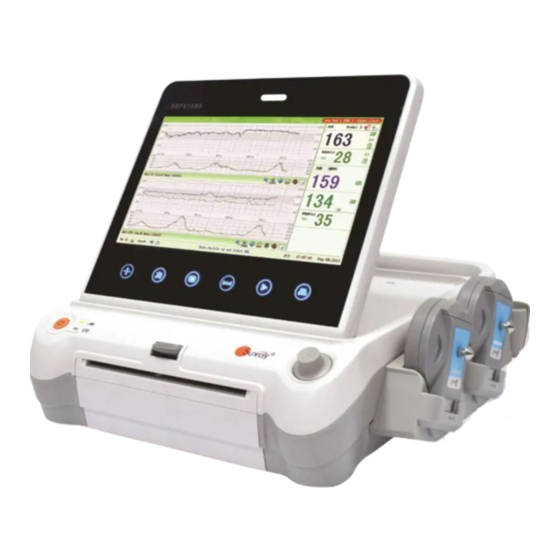
The SRF618B6 Fetal Monitor provides Non-Stress testing for pregnant women from the approximately 28 week of gestation. The SRF618B6 Fetal Monitor is intended for non-invasive monitoring of the Fetal Heart Rate (FHRs), Uterine Activity (UA), and Fetal Movement (FM) during antepartum testing. - Page 12 ’ ’ ’ FHR3 Socket 10 FHR2 Socket 11 FHR1 Socket 12 Fetal Movement Marker (FM) Socket 13 TOCO Socket 14 Wired Transducer Holder(optional) [Fig.2-2: Left side view] 15 Power cord connector 16 Fuse-holder 17 Handle 18 RS-232 Interface 19 RS-485 Interface 20 RJ45 Interface 21 USB Socket 22 Antenna Interface...
- Page 13 ’ ’ ’ Fig. 2-6: Control Knob The Monitor is a user-friendly device with operation conducted by a few keys on the front panel and the control knob. Their functions are as follows. 1) Keys Name Function Description Zero key Adjust the external TOCO contractions trace/value to preset unit.
-
Page 14: Accessories
’ ’ ’ 2.4 Accessories The accessories should be connected to the monitor via the sockets on the left side and right side panels. Each accessory has a tab on the connector housing to ensure proper insertion into the appropriate socket on the monitor. -
Page 15: Screen
’ ’ ’ Wireless TOCO Transducer Sensor Front view Back view Fig 2-10: Wireless TOCO Transducer 2.4.3 Fetal Movement Marker 1. Marker Connector 2. Press key Fig 2-11: Fetal Movement Marker 2.5 Screen 2.5.1 Main Interface 1. Alarm message window 2. - Page 16 ’ ’ ’ The main interface of the monitor displays numbers, traces, menus and monitor status information. The screen background color has three choices: black, green and pink. To change the screen color, please refer to the section 6.1 System setting 2) Screen Color. According to the content, the main interface is divided into four windows: (1) Alarm Message Window (2) Numeric Window (3) Status Window (4) Trace/ Menu Window.
-
Page 17: Ordering Information
’ ’ ’ Print Turn on the Voice for FHR Turn off the Voice for FHR Tools menu, including the submenus of Patient information, Record List, Alarm list and Analysis result 2.6 Ordering Information Repair parts, along with part numbers, are listed in the tables that follow. Description Part No. - Page 18 ’ ’ ’ CAUTION Replacement of all above accessories can be performed by the operator. But only the accessories supplied or recommended by the manufacturer are allowed connected to the monitor. ~13~...
-
Page 19: Chapter 3 Installation Guide
’ ’ ’ Chapter 3 Installation Guide NOTE: Installation must be carried out by qualified personnel authorized by the manufacturer. 3.1 Unpacking and checking Unpack all external packing for the monitor and its accessories. Check all items according to the Packing List. Check the monitor and its accessories for any damage. -
Page 20: Installation
’ ’ ’ When the battery configuration is provided, after the device is transported or stored, the battery must be charged. Connecting to power supply will charge the battery no matter if the monitor is powered on. 3.3 Installation The monitor can be placed on a flat surface, or be installed on a wall or a trolley. -
Page 21: Chapter 4 Alarm
’ ’ ’ Chapter 4 Alarm 4.1 Alarm classification The monitor has two types of alarm: physiological alarm and technical alarm. Physiological alarms indicate the situation of vital sign exceeding its configured limit. They can be disabled. The adjustable alarm limits determine the conditions that trigger the alarm. Technical alarms indicate that the monitor cannot measure and therefore cannot detect critical patient conditions reliably. -
Page 22: Visual Alarm
’ ’ ’ Select the MENU key on the main interface. Select System Setting > Login. Enter the ID and password, and Confirm Select Alarm volume with the numeric or OFF. Select Save. When the alarm volume is off, the alarm Audio Off symbol (flashing) will be shown in the Status Window. -
Page 23: Alarm Treatment Measures
’ ’ ’ Fig.4-1 Fig. 4-2 For the patient file Press the MENU key on the main interface, you may enter the setting interface. Rotate the control knob until the cursor on the Load Files, and press the control knob, you may enter the files listed, shown as Fig.4-3. -
Page 24: Testing Alarms
’ ’ ’ heard or the alarm messages can be seen, so necessary measures can be taken when an emergency occurs. When the monitor gives out an alarm and catches your attention, you should: Check the patient’s condition. Identify the cause of the alarm. -
Page 25: Alarm Information
’ ’ ’ FHR Alarm Delay 0~300 second(s), in increments of 5 5 seconds NOTE: You can not disable physiological alarm and change the limitation without password. This senior function is only for service or maintenance. 4.8 Alarm information Fetus monitor specific alarm information and prompt information 4.8.1 Physiological alarm: Alarm message... -
Page 26: Chapter 5 Printing
Press the Paper Eject Button to open the paper drawer, as shown on Fig.5-1. Unfold the top page of a loading paper, place the “SUNRAY CO., LTD.” marking to the left, and then slide the paper into the paper drawer. Pull the top page of the loading paper out of the drawer, as shown on Fig.5-2. -
Page 27: Choosing Paper Speed
’ ’ ’ Choosing Paper Speed You can choose a paper speed of 1 cm/min, 2cm/min or 3cm/min: Select the MENU key on the main interface. Select System Setting > Printer Settings>CTG Print Speed. Select 1 cm/M, 2 cm/M or 3 cm/M (default). Select Save. -
Page 28: Print The Traces
’ ’ ’ Fig.5-5 Select the printing end time: Repeat the operation in step 3) to select the printing end time. The range between the two red lines is the selected printing range. Printing range Fig.5-6 5.6 Print the traces For the patient being monitored, ... -
Page 29: Understanding Recorder Paper Printout
’ ’ ’ the print key , it will print the selected range. If you don’t select the printing range, long press the print key, it will print the completed traces. If you have set the print time, it will print for the pre-set time period. During printing, you can long press the print key to stop the printing. -
Page 30: Tearing Off The Paper
’ ’ ’ 5.8 Tearing Off the Paper When recording is done, tear off the recording paper along the folding line. ~25~... -
Page 31: Chapter 6 Settings
’ ’ ’ Chapter 6 Settings What the monitor displays, and the way it operates, is controlled by its settings. All settings can be conducted by a few keys on the front panel and the control knob. They determine screen content, layout, high and low alarm limits and so forth. - Page 32 ’ ’ ’ Fig.6-2 The system setting parameters are as follows: Language : there two options, Chinese and English; Screen Color: the screen background color has three choices: classic black, fresh green, and warm pink; Alarm Volume: OFF, 1, 2, 3, and 4 adjustable. Note: if alarm volume setting is “OFF”, no audible alarm will be issued when any alarm occurs.
- Page 33 ’ ’ ’ and System available. 12) Machine Version: this function is only used by maintenance person authorized by manufacturer. 13) Hardware setting: this function is only used by maintenance person authorized by manufacturer. 14) Software setting: this function is only used by maintenance person authorized by manufacturer.
- Page 34 ’ ’ ’ Fig.6-5 19) Change password:You can set the new password here, see Fig.6-5. Note: Only the authorized person with the ID and password could change the password. Refer to 18) of this section for the Login of authorized ID. After login, you can change the password.
- Page 35 ’ ’ ’ differentiating the traces easier, the trace for FHR2 is offset by -20 bpm, and the trace for FHR3 is offset by +20 bpm. In other words, the trace for FHR2 is recorded 20 bpm lower than it really is, while the trace for FHR3 is recorded 20 bpm higher than it really is. The trace for FHR1 is never shifted.
- Page 36 ’ ’ ’ 16) Wireless Transducer No.: from 1~16 adjustable. Before set the No., see section 8.7 Using Wireless Transducers. 17) Log on: select the Log on, and enter the system login interface, see Fig.6-8. Input the ID and password, and select “Confirm”. Then login the authorized setting interface, you can set the FHR Pane Range, FHR High/Low Limit, Time-to-alarm and change password.
-
Page 37: Chapter 7 Pre-Monitoring Preparation
’ ’ ’ Chapter 7 Pre-monitoring Preparation 7.1 Switching On WARNING: Check if all the metal parts are linked to the protective earth cord and the cord is in good condition before switching on the monitor. If any sign of damage is detected, or the monitor displays some error messages, do not use it on any patient. -
Page 38: Placing Transducers In The Holder
’ ’ ’ When disconnecting a transducer, pinch the after body of the transducer plug and pull it out slightly. NOTE: Never try to disconnect the transducer by pulling the cable directly. The fetal heart rate transducer is different from the uterine contraction pressure transducer. 7.5 Placing Transducers in the Holder In order to protect the transducers, place the not-in-use transducers in the holder. - Page 39 ’ ’ ’ Since this instrument is a monitoring type instrument, which uses an advanced and unique algorithm, the detected fetal heart rate signal, uterine contraction pressure signal and fetal movement signal will be delayed for approximately 3 seconds before they are displayed. This has no adverse effect on the clinical value of this instrument, on the contrary, this will be helpful for this instrument to capture each fetal heart beat more NOTE: When the Doppler Transducer is put not on the back but on the breast part of fetus, accurate...
-
Page 40: Chapter 8 Fetal Monitoring
’ ’ ’ Chapter 8 Fetal Monitoring WARNING: Always check if the alarm settings are appropriate for your patient before starting monitoring. Check for any fault of the transducers before applying them to the patient. Using a mixture of wired transducers and wireless transducers is not supported. When the monitor is used on multiple pregnant women, you can only use wired US transducers and wired TOCO transducers on one pregnant woman, and wireless US/TOCO transducers on the other pregnant women. - Page 41 ’ ’ ’ heart signal can be obtained through the fetal back. See the Fig.8-1 as below. During parturition, the fetal heart moves downward as the labor progresses. It is recommended to move the transducer along with the fetus. Fig.
-
Page 42: Monitoring Twin Fhrs
’ ’ ’ Technical Description: The fetal heart sound issued by the monitor is not the real fetal heart beating sound, and there is not much diagnostic value with its sound quality either. Actually, the fetal heart sound issued by the monitor is the sound signal derived from fetal heart pulse through multiple times of conversion of physical variables of ultrasound signal and electronic signal, indicating the movement information of fetal heart beat. -
Page 43: Monitoring Uterine Activity Externally
’ ’ ’ transducers are fixed, make sure FH sounds from three channels are clear, three FHR traces and three FHR numerics are displayed on the screen. NOTE: To ensure that three transducers stay at the optimum location, each transducer should be fixed with a separate belt. -
Page 44: Monitoring Fetal Movement
’ ’ ’ 8.5.3 Changing UA Baseline You can change the UA baseline to 0, 5, 10 (default), 15 or 20. Please refer to the section 6.2 Fetal setting 15) TOCO baseline. 8.5.4 TOCO Sensitivity If the TOCO sensitivity is too high, and the TOCO trace exceeds the paper scale, you can reduce the TOCO sensitivity to 50%. -
Page 45: Start Monitoring
’ ’ ’ 8.7 Using Wireless Transducers The monitor can collocate with two wireless FHR transducers and one wireless TOCO transducer optionally. When you use the wireless transducers, please note the following: When it is turned on, verify the power and wireless signal indicators of each wireless transducer are normal. -
Page 46: Reviewing
’ ’ ’ Fig. 8-3 Fig. 8-4 Use the soft keyboard and control knob to enter the patient File No., testing Date and Time, patient’s Name, patient’s Age, Gestation Week, G/P information (G: number for gestation and labor), Bed No., Outpatient No., and Hospital Admission No. -
Page 47: Delete Files
’ ’ ’ the left edge of the screen at a high speed. Note: If the monitor is monitoring, the function of Lode Files is invalid that you can’t review the previous traces. Fig. 8-5 8.11 Files Delete Press the MENU key on the main interface, you may enter the setting interface. -
Page 48: Fetal Monitoring Display
’ ’ ’ Fig.8-6 8.12 Fetal Monitoring Display 8.12.1 Traces WARNING Due to the LCD size, resolution and system settings, the traces displayed on the screen may look different from the recorder printout. The printout should prevail when making diagnoses. FHR3 Trace FHR1 Trace FHR2 Trace... - Page 49 ’ ’ ’ During monitoring or reviewing, the fetal monitoring trace window displays two types of traces: FHR trace, and TOCO trace. The FHR 1, FHR 2 and FHR 3 traces in one patient’s (bed’s) fetal monitoring display means triple FHRs, and FHR 1& FHR 2 traces in one patient’s (bed’s) fetal monitoring display means twin FHRs FHR Trace The y-axis of the trace indicates the numerics of FHR.
- Page 50 ’ ’ ’ responsibility of qualified medical staff to do the diagnostic interpretation of the waveform. CTG analyzing NOTE: CTG analysis can only start after the real-time trace has been printed for 10 minutes. The CTG analysis result is for reference only. After the real-time trace is printed for 10 minutes, press the Bed key and rotate the control knob to select the Tools menu key , press the control knob...
- Page 51 ’ ’ ’ At the end of the printing, the recorder prints the CTG analysis results of this moment on the recorder paper. Be aware that CTG analysis result is a calculation output. It can be used as a reference to assist medical personnel in making correct diagnosis, instead of replacing it.
-
Page 52: Chapter 9 After Monitoring
’ ’ ’ Chapter 9 After Monitoring 9.1 Completing Monitoring After monitoring, Remove transducers or electrodes from the patient; wipe the remaining gel off the patient and the transducer with a clean soft cloth or tissue. Long press the PRINT key to stop printing. Wait the paper to stop and then tear it off along the perforation. -
Page 53: Chapter 10 Maintenance And Cleaning
’ ’ ’ Chapter 10 Maintenance and Cleaning 10.1 Maintenance 10.1.1 Maintaining Inspection Visual Inspection Prior to using the monitor every time, do the following inspections: Check the monitor and accessories to see if there is any visible evidence of damage that may affect patient safety. - Page 54 ’ ’ ’ Scratching and damaging the screen should be avoided. 10.1.3 Maintenance of Transducers Keep the transducers in a dry environment, where the temperature had better be lower than +45°C (+115 ºF). Gel must be wiped from the US transducer after use. These precautions will prolong the life of the transducer.
-
Page 55: Cleaning And Disinfecting Of Reusable Belts
’ ’ ’ Allow cleaning solutions or transducers to exceed a temperature of 45°C (113°F). Autoclave the transducers and cables or heat them above 70°C (158 °F). Caution: Do not immerse the transducers during any stage of the cleaning/disinfection process. ... -
Page 56: Cleaning Of Recorder
’ ’ ’ 10.4 Cleaning of Recorder The recorder platen, thermal print head and paper sensing mechanism must be cleaned at least once a year or when needed (when traces become faint). To do this: Clean the recorder platen with a lint-free cloth dampened in soap/ water solution. ... -
Page 57: Chapter 11 Product Specifications
’ ’ ’ Chapter 11 Product Specifications 11.1 Safety Classifications Item Specification Anti-electroshock type Class I equipment with internal power supply Anti-electroshock degree US/TOCO/FM : Type B Explosion proof level Ordinary equipment, without explosion proof Degree of Protection against Main Unit: IPX0 Harmful Ingress of Water US/TOCO Transducers: IPX8 Other Accessories: No liquid ingress protection... - Page 58 ’ ’ ’ 11.4 Performance Specifications Fetal monitoring (FHR, TOCO, FM) Technique: ultrasonic pulse Doppler Ultrasonic operating frequency: 0.8MHz~5.0MHz US frequency: 2MHz Spatial-average pulse-average intensity (I ): <20mW/cm SAPA Offset with nominal frequency: ≤±10% Ultrasound Mechanical index MI: < 1 Thermal index for soft tissue TIS: <...
- Page 59 ’ ’ ’ 11.6 Rechargeable Lithium-ion Battery of the equipment Type: Rechargeable Lithium-ion Battery Continual Working Time: 2 hours ~ 4 hours (depending on the configuration) Necessary Charge Time: 4 hours ~ 5 hours Nominal Capacity: 4000mAh Nominal Voltage: 11.1V Charge Mode: Constant current/ constant voltage(CC-CV)...
-
Page 60: Chapter 12 Abbreviation
’ ’ ’ Chapter 12 Abbreviation The abbreviations used in this manual and their full names are listed below: Abbreviation Full Name Alternative Current Cardiotocography Ultrasound (Transducer) Fetal Heat Rate Tocotonometer TOCO Uterine Activity (TOCO) Fetal Movement Non Stress Test Magnetic Resonance Imaging Liquid Crystal Display Identity... -
Page 61: Chapter 13 Emc Information
’ ’ ’ Chapter 13 EMC Information The device and its accessories, listed in the accessories section, comply with the following EMC standards: • EN/IEC 60601-1-2: 2001+A1:2004 Take special precautions regarding electromagnetic compatibility (EMC) when using medical electrical equipment. You must operate your monitoring equipment according to the EMC information provided in this book. - Page 62 Table 2-Guidance and manufacture’s declaration – electromagnetic immunity The SRF618B6 is intended for use in the electromagnetic environment specified below. The customer or the user of the SRF618B6 should assure that it is used in such an environment.
- Page 63 Table 3. Guidance and manufacturer’s declaration – electromagnetic immunity The SRF618B6 is intended for use in the electromagnetic environment specified below. The customer or the user of the SRF618B6 should assure that it is used in such an environment.
- Page 64 To assess the electromagnetic environment due to fixed RF transmitters, an electromagnetic site survey should be considered. If the measured field strength in the location in which the SRF618B6 is used exceeds the applicable RF compliance level above, the SRF618B6 should be observed to verify normal operation.
-
Page 65: Ultrasonic Related Information
’ ’ ’ Chapter 14 FCC Statement Caution: The user is cautioned that changes or modifications not expressly approved by the party responsible for compliance could void the user's authority to operate the equipment. This device complies with Part 15 of the FCC Rules. Operation is subject to the following two conditions: (1) this device may not cause harmful interference, and (2) this device must accept any interference received, including interference that may cause undesired operation. - Page 66 4.258. A value of K was chosen which corresponds to a 90% probability that 90% of all probes would fall below the calculated limits X. The following table presents the calculated values using the 4.258 value for K. Table 2 Results for SRF618B6 Transducers Wired FHR Transducer...
- Page 67 ’ ’ ’ Results Track 1 Reporting Table show the worst-case indices for each Transducer tested. ~62~...
- Page 68 ’ ’ ’ Acoustic Output Report ACOUSTIC OUTPUT REPORTING TABLE TRACK 1 Non-Auto-scanning Mode System Model: Fetal Monitor, Model: SRF618B6 Transducer: Wired FHR Transducer (3 samples for this type of transducer) Operating Mode: PW-Mode Application(s): Fetal SATA SAPA Acoustic Output (mW/cm²)
- Page 69 ’ ’ ’ ACOUSTIC OUTPUT REPORTING TABLE TRACK 1 Non-Auto-scanning Mode System Model: Fetal Monitor, Model: SRF618B6 Transducer: Wireless FHR Transducer (3 samples for this type of transducer) Operating Mode: PW-Mode Application(s): Fetal SATA SAPA Acoustic Output (mW/cm²) (mW/cm²) 0.73 10.13...
- Page 70 ’ ’ ’ Uncertainties The uncertainties in the measurements were predominantly systematic in origin; the random uncertainties were negligible in comparison. The overall systematic uncertainties were determined as follows: Hydrophone calibration The uncertainty in the calibration of the hydrophone including the pre-amplifier is determined to be 1dB (1MHz-15MHz,±12.2%),1.5dB(15MHz-20MHz,±18.9%).
-
Page 71: Chapter 15 Troubleshooting
’ ’ ’ Chapter 16 Troubleshooting Note: Those items with a ※ prefix must be handled by professionals of our company. Location Problem Possible Causes Solutions Power cable is loose. Tighten the power cable. No display, power Display The fuse is blown. Change the fuse. - Page 72 TOCO transducer is far higher than transducer. Change the position of than 100 unit) the average numeric. TOCO transducer, if necessary. Sunray Medical Apparatus Co., Ltd. Address: 4/F No.242 Tianhe Dong Road, Guangzhou, People’s Republic of China Zip Code: 510620 Tel: 86-20-87597231 Fax: 86-20-87583004 ~67~...
Need help?
Do you have a question about the SRF618B6 and is the answer not in the manual?
Questions and answers