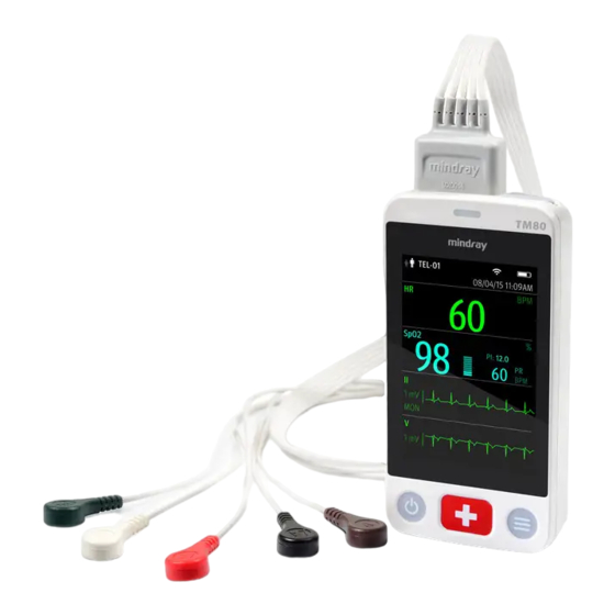
BeneVision TM80 Operator's Manual
Telemetry monitor
Hide thumbs
Also See for TM80:
- Operator's manual (276 pages) ,
- Operator's manual (240 pages) ,
- Operator's manual (240 pages)
Table of Contents
Advertisement
Quick Links
Advertisement
Table of Contents

Related Manuals for BeneVision TM80


Summary of Contents for BeneVision TM80
- Page 1 BeneVision TM80 Telemetry Monitor Operator’s Manual...
- Page 3 Introduction 0123 © Copyright 2015-2019 Shenzhen Mindray Bio-Medical Electronics Co., Ltd. All rights reserved. For this Operator’s Manual, the issue date is April 2019. TM80 Telemetry Monitor Operator’s Manual...
- Page 4 Mindray in China and other countries. All other trademarks that appear in this manual are used only for editorial purposes without the intention of improperly using them. They are the property of their respective owners. TM80 Telemetry Monitor Operator’s Manual...
- Page 5 Only skilled/trained clinical professionals should operate this equip- ment. • It is important for the hospital or organization that employs this equip- ment to carry out a reasonable service/maintenance plan. Neglect of this may result in machine breakdown or personal injury. TM80 Telemetry Monitor Operator’s Manual...
- Page 6 Malfunction or damage caused by improper operation or repair by unqualified or unauthorized service people. ■ Malfunction of the instrument or part whose serial number is not legible. ■ Others not caused by instrument or part itself. TM80 Telemetry Monitor Operator’s Manual...
- Page 7 Mindray Building, Keji 12th Road South, High-tech Industrial park, Nanshan, Shenzhen 518057, P.R.China Website: www.mindray.com E-mail Address: service@mindray.com Tel: +86 755 81888998 Fax: +86 755 26582680 EC-Representative: Shanghai International Holding Corp. GmbH (Europe) Address: Eiffestraβe 80, 20537 Hamburg, Germany Tel: 0049-40-2513175 Fax: 0049-40-255726 TM80 Telemetry Monitor Operator’s Manual...
- Page 8 Conventions ■ Italic text is used in this manual to quote the referenced chapters or sections. ■ [ ] is used to enclose screen texts. → is used to indicate operational procedures. ■ TM80 Telemetry Monitor Operator’s Manual...
-
Page 9: Table Of Contents
3.5.2 Securing Pouches for TM80 and BP10 ........ - Page 10 6.6.2 Restarting the TM80 ........
- Page 11 8.10.1 Automatically Initiating an ECG Relearning .......8 - 36 TM80 Telemetry Monitor Operator’s Manual...
- Page 12 11.3 Unpairing the TM80 with the BP10 ........
- Page 13 11.4 Screen Display after Pairing a TM80 with a BP10 .......
- Page 14 16.2 Physiological Alarm Messages at the TM80 ........
- Page 15 17.3 Cleaning and Disinfecting the TM80 ........
- Page 16 E Declaration of Conformity ............E - 1 TM80 Telemetry Monitor Operator’s Manual...
-
Page 17: Safety
Safety Safety Information....................1-2 Equipment Symbols....................1-7 TM80 Telemetry Monitor Operator’s Manual 1 - 1... -
Page 18: Safety Information
Indicates a potential hazard or unsafe practice that, if not avoided, could result in minor personal injury or product/property damage. NOTE • Provides application tips or other useful information to ensure that you get the most from your product. 1 - 2 TM80 Telemetry Monitor Operator’s Manual... -
Page 19: Warnings
• The TM80 Telemetry Monitor is not to be used in the vicinity of electro- surgical units because such use may interrupt or interfere with the transmission of signals from the TM80 Telemetry Monitor. - Page 20 Route, wrap and secure the cables to avoid inadvertent disconnection, stumbling and entanglement. • Instruct patients not to interact with the display of the TM80 Telemetry Monitor and not to open the battery compartment while the TM80 Telemetry Monitor is in use.
-
Page 21: Cautions
Safety Information 1.1.2 Cautions CAUTION • Do not let the display of the TM80 Telemetry Monitor directly touch the patient’s skin when the display is on. • When the CMS presents the alarm “Offline”, check the network connec- tion status. -
Page 22: Notes
Safety CAUTION • At the end of its service life, the TM80 Telemetry Monitor and its acces- sories must be disposed of in compliance with the guidelines regulating the disposal of such products to prevent bringing potential negative consequences to the environment and human health. If you have any questions concerning disposal of the equipment, please contact Min- dray. -
Page 23: Equipment Symbols
Annex I of this directive. Note: The product complies with the Council Directive 2011/65/EU. Dispose of in accordance with the local country’s requirements NOTE • Some symbols may not appear on your equipment. TM80 Telemetry Monitor Operator’s Manual 1 - 7... - Page 24 Equipment Symbols Safety This page intentionally left blank. 1 - 8 TM80 Telemetry Monitor Operator’s Manual...
-
Page 25: General Product Description
General Product Description Intended Use ......................2-2 Applied Parts ......................2-2 Key Features.......................2-3 Components ......................2-3 Physical View ......................2-4 Screen Display Status .....................2-5 TM80 Telemetry Monitor Operator’s Manual 2 - 1... -
Page 26: Intended Use
• As the TM80 Telemetry Monitor transmits data wirelessly, there might be a risk of data loss. The TM80 Telemetry Monitor should not be used for primary monitoring in applications where momentary loss of the ECG is unacceptable at the Central Station. -
Page 27: Key Features
Audio feedback for out-of-range and lost device. ■ Communicates with the Central Station via WLAN. ■ Displays the battery gauge on the TM80 and at the Central Monitoring System (hereinafter called CMS) ■ Provides disposable and reusable pouches with clear front that closes securely... -
Page 28: Physical View
General Product Description Physical View Display Activation (Power On/Off ) button ■ When the TM80 is powered off, pressing this button will turn it on. ■ When the TM80 is powered on: ◆ If the screen display is on, pressing this button will turn it off. -
Page 29: Screen Display Status
TM80 and at the CMS, if networked connected. ■ If the TM80 is not connected to the CMS, the “No Central Monitoring” message will display in the prompt message area of the TM80. When the display of the TM80 is off: ■... - Page 30 WARNING • The temperature of the display rises when the TM80’s display is on and the TM80 is connected to the CMS. If the display contacts the patient’s skin for a long time, skin burns may occur. Do not let the display directly touch the patient’s skin when the display is on.
-
Page 31: Getting Started
Getting Started Unpacking and Checking..................3-3 Environmental Requirements ................3-3 Preparation.........................3-4 Powering On the TM80 ..................3-9 Using the Pouch .......................3-10 TM80 Telemetry Monitor Operator’s Manual 3 - 1... - Page 32 The TM80 shall be installed by Mindray authorized personnel. • The software copyright of the TM80 is solely owned by Mindray. No organization or individual shall resort to altering, copying, or exchang- ing it or to any other infringement on it in any form or by any means without due permission.
-
Page 33: Unpacking And Checking
The operating environment of the TM80 should be reasonably free from noises, vibra- tion, dust, corrosive, flammable and explosive substances. When the TM80 is moved from one place to another, condensation may occur as a result of temperature or humidity difference. In this case, never start the system before the condensation disappears. -
Page 34: Preparation
IEEE 802.11, external radio frequency and network interference may result in occasional data dropout of waveform data. This is a normal phenomenon. Contact Mindray for any questions regarding the electro- magnetic environment in the field where the TM80 is to be installed. Preparation 3.3.1... - Page 35 ◆ ECG signal quality ◆ Water resistance • Do not use the ECG leadwire to move or lift the TM80. This may cause the TM80 to fall, thus damaging the equipment or injure the patient. NOTE • Insert the SpO...
-
Page 36: Installing The Batteries
3.3.2 Installing the Batteries You can use AA batteries or a rechargeable lithium-ion battery to power the TM80. The runtime of the TM80 is dependent on the battery solution that you chose. Usually, a rechargeable lithium-ion battery will provide the longest runtime. For details about the recommended AA batteries, refer to Miscellaneous on Page 19-5. - Page 37 Open the battery compartment by lifting up on both bottom sides of the com- partment door. Insert three AA 1.5V Alkaline batteries into the AA battery tray, matching the polar- ity with the +indications inside the battery tray as shown below. TM80 Telemetry Monitor Operator’s Manual 3 - 7...
- Page 38 Press down the battery tray until it closes firmly as indicated by the arrow in the following figure. 3 - 8 TM80 Telemetry Monitor Operator’s Manual...
-
Page 39: Powering On The Tm80
If the TM80 is turned on for the first time, the equipment will request you to configure first time startup. Please make your desired configurations as prompted. ■ If the TM80 is turned on next time, the equipment will prompt whether it is a new patient. Select [Yes] or [No] as desired. WARNING •... -
Page 40: Using The Pouch
The TM80 is not intended for direct contact with the patient’s skin. During normal use, the TM80 should be worn over clothing, in a pocket, or preferably in a pouch. The pouch with clear front is an appropriate means for holding the TM80. Both disposable and reus- able pouches specified in this manual can be used for the TM80. -
Page 41: Securing The Pouch For Tm80
Securing the Pouch for TM80 To secure the pouch, follow this procedure: Place the TM80 into the pouch with the ECG leadwires and the SpO sensor cable, if used, exiting from the pouch opening, as shown in the following figures. - Page 42 NOTE • The pouch is used only for the TM80. The pouch cannot be used for car- rying other personal devices, such as a mobile phone. 3 - 12 TM80 Telemetry Monitor Operator’s Manual...
-
Page 43: Securing Pouches For Tm80 And Bp10
When a patient wears the pouches for the TM80 and BP10 simultaneously, follow steps in 3.5.1 Securing the Pouch for TM80 to secure the pouch for the TM80 on the patient’s waist and follow steps in BP10 NIBP Module Operator’s Manual to secure the pouch for the BP10 on the patient’s waist or arm. - Page 44 Using the Pouch Getting Started Wearing pouches with BP10 on the arm 3 - 14 TM80 Telemetry Monitor Operator’s Manual...
-
Page 45: Basic Operations
Basic Operations Overview........................4-2 Understanding the Touch Screen Gestures............4-5 Basic Operations.......................4-5 TM80 Telemetry Monitor Operator’s Manual 4 - 1... -
Page 46: Overview
This chapter gives you an overview of basic operations related to the TM80. The princi- ple method of operating your TM80 is via the touch screen. Almost every element on the display is interactive. Display elements include measurement numerics, information prompts, waveforms, quick keys, menus, and so on. -
Page 47: On-Screen Keyboard
You may also tap this area to display the setup menu for the corresponding parameter/waveform. 4.1.2 On-Screen Keyboard The TM80 uses an on-screen keyboard to enter alphanumeric information, such as the device name and passwords. TM80 Telemetry Monitor Operator’s Manual 4 - 3... - Page 48 Accept button: tap to save the settings and exit the keyboard. Space button: tap to input a space. Alphabetic switch button: tap to switch to the alphabetic keyboard. More punctuation buttons: tap to display the punctuation keyboard. 4 - 4 TM80 Telemetry Monitor Operator’s Manual...
-
Page 49: Understanding The Touch Screen Gestures
Basic Operations Understanding the Touch Screen Gestures Understanding the Touch Screen Gestures Before using the TM80, understand the supported touch screen gestures: Gesture Action Description Briefly touch the surface with your fingertip to select a target. Press and hold Touch the surface for an extended period of time. - Page 50 Provides an option to operate a func- tion. Drag to right to enable the switch; drag Switch to left to disable the switch. : exits the current menu and returns to the previous menu or the main screen. 4 - 6 TM80 Telemetry Monitor Operator’s Manual...
-
Page 51: Understanding The Screen Display Orientation
Basic Operations Basic Operations 4.3.2 Understanding the Screen Display Orientation The TM80 supports both the portrait and landscape display orientations. Example of landscape display Example of portrait display ■ Portrait: both digital and waveform tiles take up the entire width of the screen. -
Page 52: Displaying The Quick Keys Area
Tap the button to notify the CMS to save the event to the event database. The “Event Marked” message displays in the prompt message area. The marked event is also saved on the events review page of the TM80. Alarm Reset Tap the button to reset the alarm system. -
Page 53: Turning The Display Off
4.3.8 Configuring the Screen Lock Configuring the screen lock can help prevent unauthorized operations made on the TM80. For how to set the screen lock, refer to Screen Lock Menu on Page 13-14. 4.3.9 Unlocking the Screen in Locked Mode If you set [Screen Lock] to [Locked] or [View Only], you need to input the correct pass- code to unlock the screen after the display turns off. -
Page 54: Acknowledging The Nurse Call
Do not rely exclusively on the nurse call function. The medical personnel should also pay close attention to the patient’s condition. For details about how to trigger a nurse call, refer to Physical View on Page 2-4. 4 - 10 TM80 Telemetry Monitor Operator’s Manual... -
Page 55: User Configurations
User Configurations Introduction.......................5-2 Configuring the Display..................5-2 Configuring the Audio Volume................5-5 TM80 Telemetry Monitor Operator’s Manual 5 - 1... -
Page 56: Introduction
For details about the display orientation, refer to Understanding the Screen Display Ori- entation on Page 4-7. NOTE • The TM80 must be restarted for the default display orientation selected to be effective. • Once the default display orientation takes effective, you can switch the display orientation by following steps in Switching the Screen Display Orientation on Page 4-7. -
Page 57: Understanding Portrait Orientation Display Rules
Digital areas shall be paired with the next available digital area to satisfy rule 4. This means that a digital area may be moved ahead of a waveform area if a half of a row needs to be filled. TM80 Telemetry Monitor Operator’s Manual 5 - 3... -
Page 58: Configuring The Landscape Display
Three options display: [2], [3], and [4]. Tap an option to set the row numbers. The selected option displays to the right of [Rows]. Tap [Landscape Order] to enter the [Landscape Order] menu. 5 - 4 TM80 Telemetry Monitor Operator’s Manual... -
Page 59: Configuring The Display Brightness
In the [Sounds], [Touch Screen Click], or [Systole Beep] section, drag the slider to the left or right to decrease or increase the volume. Press to return to the main screen. The audio volume of alarms ranges from 45 dB to 85 dB. TM80 Telemetry Monitor Operator’s Manual 5 - 5... - Page 60 It indicates that the alarm sound is turned off. • When your TM80 is connected to the CMS and [Sounds] is turned off, [Sounds] automatically changes to [2] if the CMS is disconnected. 5 - 6...
-
Page 61: Patient Management
Patient Management Introduction.......................6-2 Admitting a Patient ....................6-2 Changing Patient Information ................6-2 Changing the Paced Status ..................6-3 Exiting the Standby Mode ..................6-6 Discharging the Patient ..................6-6 TM80 Telemetry Monitor Operator’s Manual 6 - 1... -
Page 62: Introduction
Introduction The chapter describes how to admit a patient, change patient information, enter and exit the Standby mode, and discharge the patient at the TM80. Admitting a Patient After discharging the current patient, you can admit a new patient by pressing . -
Page 63: Changing The Paced Status
If the paced status setting is not correct, tap [Paced] and select the correct option. ◆ When [Paced] is set to [Yes] at the TM80, if pace pulses are detected, the symbol displays in the waveform area of the Central Monitoring Sys- tem’s screen, and the pace pulse marks will display on the ECG waveform... -
Page 64: Changing The Department Name, Room Number, And Bed Number
Be sure to keep a close eye on patient’s with pacemaker devices. • The radio frequency energy of the TM80 or other radio frequency sources, when used in close proximity to a pacemaker, may interfere with pacemaker performance. Internal pacemakers are less vulnerable than external pacemakers due to the shielding effects of the body. -
Page 65: Entering The Standby Mode
Entering the Standby Mode NOTE • After a TM80 is connected to the Central Station, when it enters or exits Standby mode, the Central Station is also notified to enter or exit Standby mode. Refer to BeneVision Central Monitoring System Operator’s Manual for details. -
Page 66: Exiting The Standby Mode
Discharging the patient will stop monitoring at the TM80 and CMS. After discharging the patient, the patient’s configuration is cleared at the TM80. The TM80 can admit next new patient by applying the user configuration. If the TM80 does not save the user configura- tion, it will apply the factory configuration for the new patient. -
Page 67: Restarting The Tm80
Patient Management Discharging the Patient 6.6.2 Restarting the TM80 To restart the TM80, follow this procedure: If the TM80 is powered off, press to turn on the TM80. The device prompts whether this is a new patient or not. Tap [Yes] if this is a new patient. - Page 68 Discharging the Patient Patient Management This page intentionally left blank. 6 - 8 TM80 Telemetry Monitor Operator’s Manual...
-
Page 69: Alarms
Alarms Introduction.......................7-2 Alarm Safety Information..................7-2 Understanding the Alarms ...................7-3 Viewing Alarms......................7-5 Changing Alarm Settings..................7-6 Pausing Alarms ......................7-8 Resetting Alarms ......................7-9 Latching Alarms......................7-10 Actions When an Alarm Occurs ................7-10 Operator’s Position ....................7-11 TM80 Telemetry Monitor Operator’s Manual 7 - 1... -
Page 70: Introduction
• If the TM80 is connected to the CMS, alarms can be presented and con- trolled at the CMS. Remote suspension or reset of alarms at the CMS may cause a potential hazard. For more information, refer to BeneVision Cen- tral Monitoring System Operator’s Manual. -
Page 71: Understanding The Alarms
Low priority alarms require you to be aware of this condition. ■ Messages: provides additional information on the patient or the equipment. 7.3.3 Alarm Indicators When an alarm occurs, the TM80 indicates it through visual or audible alarm indications. For more information, see the following table. Medium High Priority Priority... - Page 72 NOTE • When multiple alarms of different priority levels occur simultaneously, the TM80 selects the highest priority alarm to light the alarm lamp and issue the alarm tone, • When multiple alarms of different priority levels occur simultaneously, the TM80 only displays the messages from the highest priority alarm.
-
Page 73: Alarm Status Symbols
■ : indicates that alarms are acknowledged and the alarm system is reset. Viewing Alarms If the TM80 has more than one alarm, you can view all the active alarms in the [Alarm List]. To view alarms, follow this procedure: Tap the prompt message area on the main screen. -
Page 74: Changing Alarm Settings
The TM80 provides the auto alarm limits function to automatically adjust alarm limits according to the patient’s vital signs used. When auto limits are selected, the TM80 cal- culates safe auto limits based on the latest measured values. To get accurate auto alarm limits, you need to collect a set of measured vital signs as a baseline. -
Page 75: Restoring Default Alarm Settings
In the [Setup] section, tap [Auto Limits]. In the dialog that pops up, tap [OK]. Then the TM80 will automatically calculate alarm limits based on the latest measured values. Before applying these automatically created alarm limits, confirm if they are appropriate for your patient from the Limits menu. -
Page 76: Pausing Alarms
When the TM80 is connected to the CMS and the function of remotely pausing alarms is enabled at the CMS, alarms can be paused either at the TM80 or at the CMS. For information on pausing alarms at the CMS, refer to BeneVision Central Monitoring System Operator’s Manual. -
Page 77: Resetting Alarms
You can acknowledge the on-going alarms by resetting alarms. After being reset, the alarm system can respond to a subsequent alarm condition. When an alarm occurs, follow this procedure to reset the TM80’s alarm system. Press to enter the main menu. -
Page 78: Latching Alarms
Latching Alarms When physiological alarms are latched, the time when the alarm is last triggered is dis- played behind the alarm message. Resetting or pausing alarms via the TM80 or the CMS clears latched alarms. NOTE •... -
Page 79: Operator's Position
7.10 Operator’s Position The TM80 is designed that the operator can identify the alarm condition and priority from a distance of four meters, and can identify specific alarm details from a distance of one meter. During normal use, the operator is expected to face the front of the equip- ment. - Page 80 Operator’s Position Alarms This page intentionally left blank. 7 - 12 TM80 Telemetry Monitor Operator’s Manual...
- Page 81 Monitoring ECG, Arrhythmia, ST and QT Introduction.......................8-2 ECG Safety Information..................8-2 Preparation for Monitoring ECG .................8-3 Changing ECG Settings..................8-13 Configuring the HR Alarm Source..............8-17 Understanding the ECG Display .................8-18 Arrhythmia Monitoring..................8-20 QT/QTc Interval Monitoring .................8-33 Relearning ........................8-35 TM80 Telemetry Monitor Operator’s Manual 8 - 1...
-
Page 82: Monitoring Ecg, Arrhythmia, St And Qt
Operations such as configuring the QRS threshold, adjusting the ST point/ISO point/J point, configuring the ST template/QT template are performed at the CMS. For details about these operations, refer to Monitoring with the TM80 at the CMS on Page 14-1. ECG Safety Information WARNING •... -
Page 83: Preparation For Monitoring Ecg
• Give special attention to the type of electrode used. Because some elec- trodes may generate greater electric offset due to polarization. • Do not use electrodes of different metallic materials. TM80 Telemetry Monitor Operator’s Manual 8 - 3... - Page 84 Consult the electrode manufac- turer’s instructions for specific use. Ensure all the electrodes are applied to the patient properly. Secure the lead wires to the patient according to hospital practice. 8 - 4 TM80 Telemetry Monitor Operator’s Manual...
-
Page 85: Configuring The Ecg Lead Labeling
This manual presents lead placement according to the guidelines of the American Heart Association (AHA) and the International Electro-Technical Commission (IEC). Lead position Label Color Label Color Chest Brown White Left Leg Green Right Leg Green Black Left Arm Black Yellow Right Arm White TM80 Telemetry Monitor Operator’s Manual 8 - 5... -
Page 86: Placing The Electrodes
P wave or the T wave. If the R wave is not significantly larger than other lower voltage waves on the ECG tracing, the TM80 may have some difficulty in identifying the appropriate waves. For some patients, you need to adjust electrode placement and/or the viewed ECG lead to obtain a significant R wave. - Page 87 R (red) At the patient's 2nd ICS mid- clavicular line to the right of the sternum. LA (black) L (yellow) At the patient's 2nd ICS midclavicular line to the left of the sternum. TM80 Telemetry Monitor Operator’s Manual 8 - 7...
- Page 88 The positions of Va (Ca) and Vb (Cb) can also be placed at a proper position according to the clinician’s needs. RA (R) LA (L) V6 (C6) V1 (C1) V5 (C5) V4 (C4) LL (F) RL (N) V2 (C2) V3(C3) 8 - 8 TM80 Telemetry Monitor Operator’s Manual...
- Page 89 C4 (white) In the fifth intercostal space, mid-clavicular line. V5 (brown) C5 (white) In the fifth intercostal space, anterior axillary line. V6 (brown) C6 (white) In the fifth intercostal space, mid-axillary line. TM80 Telemetry Monitor Operator’s Manual 8 - 9...
- Page 90 RA (R) LA (L) LL (F) 3-wire lead placement for a pacemaker patient (AHA)/(IEC) Pacemaker RA (R) LA (L) V(C) LL (F) RL (N) 5-wire Lead Placement for a Pacemaker Patient (AHA)/(IEC) 8 - 10 TM80 Telemetry Monitor Operator’s Manual...
-
Page 91: Checking The Lead Placement
Enter the [Lead Placement] menu in either of the following ways: ■ Tap the ECG lead off message in the prompt message area of the main screen. to enter the main menu →tap [Lead Placement]. ■ Press TM80 Telemetry Monitor Operator’s Manual 8 - 11... -
Page 92: Checking The Paced Status
In the [Pacer] section, check if [Paced] is appropriate for the patient. If it is not correct, tap [Paced] and select the correct paced status. For details about the options, refer to Changing the Paced Status on Page 6-3. 8 - 12 TM80 Telemetry Monitor Operator’s Manual... -
Page 93: Maintaining Quality Ecg Signal
Cable Type Selects the current ECG leadwire type. Auto, 3 Lead, 5 Lead, 6 Lead Refer to ECG Leadwire Types on Page 8-14 for details. The factory default settings are in bold. TM80 Telemetry Monitor Operator’s Manual 8 - 13... -
Page 94: Ecg Leadwire Types
[Cable Type]. ◆ [Va] options: Va, V1, V2, V3, V4, V5, V6. Va is the default. ◆ [Vb] options: Vb, V1, V2, V3, V4, V5, V6. Vb is the default. 8 - 14 TM80 Telemetry Monitor Operator’s Manual... -
Page 95: Configuring Ecg Waveforms
■ A 2 mm dot shows above each ECG wave- form each time the pace pulse is detected. The factory default settings are in bold. TM80 Telemetry Monitor Operator’s Manual 8 - 15... -
Page 96: Configuring The Ecg Waveform Size
To configure ECG alarm settings, follow this procedure: In the [Alarms] section of the [ECG] menu, tap [ECG Alarm Setup].The [Alarm Limits] menu is displayed. Select the options described in the following table. 8 - 16 TM80 Telemetry Monitor Operator’s Manual... -
Page 97: Configuring The Notch Filter
In most cases, the HR and PR numerics are identical. In order to avoid simultaneous alarms on HR and PR, the TM80 uses either HR or PR as its active alarm source. To change the alarm source, follow this procedure: In the [Parameter Setup] section of the [ECG] menu, tap [HR]. -
Page 98: Understanding The Ecg Display
NOTE • Both the HR value displayed on the TM80’s main screen and that at the Central Station can meet relevant standards and are reliable. HR trended, alarm checking, and arrhythmia are based on the HR calculated at the Central Station. -
Page 99: About The Hr Digital Area
■ The ECG waveform area scrolls the waveform at the configured sweep speed. ■ The ECG waveform area indicates a Pacer indicator when a pace pulse is detected and Paced is enabled. TM80 Telemetry Monitor Operator’s Manual 8 - 19... -
Page 100: Arrhythmia Monitoring
So you should closely monitor patient condition during and for several minutes after the learning phase to allow the algorithm to reach optimal detection performance. 8 - 20 TM80 Telemetry Monitor Operator’s Manual... -
Page 101: Arrhythmia Events
The heart rate is greater than the tachycardia limit. Brady The heart rate is lower than the bradycardia limit. Pacer Not Capture No QRS complex detected for 300 ms following a pace pulse (for paced patients only). TM80 Telemetry Monitor Operator’s Manual 8 - 21... -
Page 102: Changing Arrhythmia Alarm Settings
[All On] switches on all arrhythmia alarms. [All Off ] switches off all arrhythmia alarms. This button becomes inactive when [Lethal Arrhy Alarms Off ] is disabled in the System Setup menu of the CMS. 8 - 22 TM80 Telemetry Monitor Operator’s Manual... - Page 103 On, Off V-Tach PVCs: 3 beats to 99 beats; the default is [6 beats]. V-Tach Rate:100 bpm~200 bpm; the default is [130 bpm]. Alarm priority: High The factory default settings are in bold. TM80 Telemetry Monitor Operator’s Manual 8 - 23...
- Page 104 Multif PVCs Window: 3 beats to 31 beats; the default is [15 beats]. Alarm priority: Prompt, Low, Med, High On, Off Alarm priority: Prompt, Low, Med, High The factory default settings are in bold. 8 - 24 TM80 Telemetry Monitor Operator’s Manual...
- Page 105 Vent Rhythm On, Off Alarm priority: Prompt, Low, Med, High Pause On, Off Pause Time: 1.5s, 2.0s, 2.5s, 3.0s Alarm priority: Prompt, Low, Med, High The factory default settings are in bold. TM80 Telemetry Monitor Operator’s Manual 8 - 25...
- Page 106 • The priority of lethal arrhythmia alarms is always high. • When the TM80 is connected to the CMS, any changes made either at the TM80 or the CMS will be communicated to the other side. • When lethal arrhythmia alarms are set to Disable at the CMS, the symbol is displayed on the lethal arrhythmia alarms at the TM80.
-
Page 107: Arrhythmia Alarms Timeout
HR High / Irr Rhythm/ Vent Rhythm Pause HR Low Irr Rhythm End Run PVCs Pacer not Capture Couplet Pacer not Pacing Missed Beats R on T Bigeminy Trigeminy PVCs/min Multiform PVC TM80 Telemetry Monitor Operator’s Manual 8 - 27... - Page 108 Alarm in high priority chain Alarm in medium priority During timeout period, alarm light and chain alarm tone are disabled. When the timeout period is reached, alarm light and alarm tone are reactivated. 8 - 28 TM80 Telemetry Monitor Operator’s Manual...
-
Page 109: Understanding The Arrhythmia Display
ST segment analysis is intended for adult and pediatric patients. When the TM80 is connected to the CMS, you can adjust ST points, enter the ST graphic window and the ST view at the CMS. For more information, refer to ST Monitoring on Page 14-6. -
Page 110: St Safety Information
ST values may be affected by such factors as some drugs or metabolic and conduction disturbances. • When the TM80 is connected to the CMS, the CMS provides information regarding changes in ST deviation levels. The clinical significance of the ST level change information should be determined by a physician. -
Page 111: Configuring St Alarm Settings
Relative ]: it is the default option. You can set the alarm properties for [ST Single] and [ST Dual] alarms. In the [Alarms] section, select the options described in the following table. TM80 Telemetry Monitor Operator’s Manual 8 - 31... - Page 112 0 mV to 2.0 mV; the default is [0.1]; the step is 0.01mV. Alarm low limit range: -2.0 mV to 0 mV; the default is [-0.1]; the step is 0.01mV. Alarm priority: Low, Med, High The factory default settings are in bold. 8 - 32 TM80 Telemetry Monitor Operator’s Manual...
-
Page 113: Qt/Qtc Interval Monitoring
QT/QTc interval monitoring is intended for adult and pediatric patients. When the TM80 is connected to the CMS, you can set the QTc formula and enter the QT view at the CMS. For more information, refer to QT Monitoring on Page 14-4. -
Page 114: Enabling Qt/Qtc Monitoring
Configuring QT/QTc Alarm Settings To configure QT/QTc alarm settings, follow this procedure: Tap the QT digital area to enter the [QT/QTc] menu. Tap [QT/QTc Alarm Setup]. Select the options described in the following table. 8 - 34 TM80 Telemetry Monitor Operator’s Manual... -
Page 115: Relearning
Relearning Changes in ECG beat morphology could result in incorrect arrhythmia alarms and/or inaccurate heart rate. ECG relearning allows the TM80 to learn the new dominant beat morphology and thus reduce false arrhythmia alarms and inaccurate HR values. Once learning is complete, the dominant QRS complex is stored as a reference template. The reference template is used as the normal morphology of that patient and it is compared with incoming beats to identify possible arrhythmias. -
Page 116: Automatically Initiating An Ecg Relearning
ECG signal is relatively noise-free. If ECG learning takes place during arrhythmias, the ectopic beats may be incorrectly learned as normal QRS complexes. This may result in missed detection of subsequent arrhythmia events. 8 - 36 TM80 Telemetry Monitor Operator’s Manual... - Page 117 Monitoring Respiration (Resp) (Optional) Introduction.......................9-2 Resp Safety Information ..................9-2 Preparation for Monitoring Resp................9-3 Changing Resp Settings ..................9-4 Understanding the Resp Display................9-7 TM80 Telemetry Monitor Operator’s Manual 9 - 1...
-
Page 118: Introduction
If you do not set the detection level for the respiration correctly in man- ual detection mode, it may not be possible for the TM80 to detect apnea. If you set the detection level too low, the TM80 is more likely to detect cardiac activity, and to falsely interpret cardiac activity as respiratory activity in the case of apnea. -
Page 119: Preparation For Monitoring Resp
ECG electrode placement is applied, the two electrodes should be RA and LL of ECG Lead II. For more information, see.8.3.4.1 Standard 3-Leadwire Electrode Placement. RA (R) LL (F) Lead II TM80 Telemetry Monitor Operator’s Manual 9 - 3... -
Page 120: Changing Resp Settings
Enabling/Disabling the Resp Functionality You can configure whether to display the Resp digital data and waveform on the main screen. To do so, follow this procedure: Press to enter the main menu. Tap [Parameter Setup]. 9 - 4 TM80 Telemetry Monitor Operator’s Manual... -
Page 121: Entering The Resp Menu
Options Description Settings* NCM Alarm Delay The TM80 will trigger the “No Chest Move- 10s, 15s, 20s, 25s, 30s, 35s, 40s ment” alarm if the patient has stopped breathing for longer than the set apnea time. This alarm is displayed on the central monitoring system only. -
Page 122: Configuring Resp Alarm Settings
When the TM80 is connected to the Central Monitoring System, switching on or off this option at the Central Monitoring System also switches it on or off at the TM80, and vice versa. After tapping this option, you can configure the alarm priority. -
Page 123: Understanding The Resp Display
1 RPM. ■ If the Resp measurement is invalid, “- - -” displays in place of the RR value. 9.5.3 Resp Waveform Area Resp lead label Resp waveform Resp waveform gain TM80 Telemetry Monitor Operator’s Manual 9 - 7... -
Page 124: About The Resp Waveform Area
About the Resp Waveform Area ■ The Resp waveform, lead label, and waveform gain display in the configured Resp color. ■ The Resp waveform area scrolls the waveform at the configured sweep speed. 9 - 8 TM80 Telemetry Monitor Operator’s Manual... - Page 125 Monitoring Pulse Oxygen Saturation (SpO ) (Optional) Introduction.......................10-2 SpO2 Safety Information..................10-2 Measurement Limitations..................10-3 Connecting and Disconnecting the SpO2 Module ........10-3 Changing SpO2 Settings ..................10-4 Performing SpO2 Measurement.................10-7 Understanding the SpO2 Display ..............10-8 TM80 Telemetry Monitor Operator’s Manual 10 - 1...
-
Page 126: Monitoring Pulse Oxygen Saturation (Spo2) (Optional)
The SpO module processes the electrical signal and displays a waveform and digital values for SpO and pulse rate. NOTE • The TM80 is calibrated to display functional oxygen saturation. 10.2 Safety Information WARNING • Only use SpO sensors specified in this manual. -
Page 127: Measurement Limitations
SpO connector in the TM80. To disconnect the SpO module from the TM80, pinch the left and right sides near the helix parts circled in red (as shown below) on the SpO module cable and pull the SpO module out horizontally. -
Page 128: Changing Spo2 Settings
] menu in either of the following ways: ■ On the main screen, tap the SpO digital area or waveform area. to enter the main menu →tap [Parameter Setup] → tap [SpO ■ Press 10 - 4 TM80 Telemetry Monitor Operator’s Manual... -
Page 129: Configuring Spo2 Settings
Color Selects the color of SpO numeric data and 16 colors waveform The default color is cyan. The factory default settings are in bold. Press to return to the main screen. TM80 Telemetry Monitor Operator’s Manual 10 - 5... - Page 130 Desat alarm properties. You can also set whether to measure SpO and NIBP simultaneously. To configure SpO alarm settings, follow this procedure: In the [Alarms] section of the [SpO ] menu, select the options described in the fol- lowing table. 10 - 6 TM80 Telemetry Monitor Operator’s Manual...
-
Page 131: Performing Spo2 Measurement
Select an appropriate sensor according to the patient category and weight. Remove colored nail polish from the application site. Apply the sensor to the patient. Connect the sensor to the SpO module and the SpO module to the TM80. TM80 Telemetry Monitor Operator’s Manual 10 - 7... -
Page 132: Understanding The Spo2 Display
Understanding the SpO2 Display Monitoring Pulse Oxygen Saturation (SpO2) (Optional) The SpO measurement displays when the TM80 detects that a sensor is con- nected to the patient. WARNING • When equipped with Mindray SpO module, use only Mindray SpO sen- sors specified in this manual. -
Page 133: About The Spo2 Digital Area
Displays PI resolution as 0.1 when the PI value is greater than or equal to 10%. ■ If the SpO measurement or PR is invalid, “- - -” displays in place of digits. TM80 Telemetry Monitor Operator’s Manual 10 - 9... -
Page 134: Spo2 Waveform Area
Provides the functionality of scrolling real-time waveform data. ■ Scrolls the waveform in the configured sweep speed. ■ Automatically scales the SpO waveform data area to maximize the vertical height of the Pleth waveform for the data range. 10 - 10 TM80 Telemetry Monitor Operator’s Manual... - Page 135 Pairing Introduction....................11-2 Pairing a TM80 with a BP10 ..................11-2 Unpairing the TM80 with the BP10 ..............11-4 Screen Display after Pairing a TM80 with a BP10 .........11-6 Interactions after Pairing a TM80 with a BP10..........11-7 TM80 Telemetry Monitor Operator’s Manual 11 - 1...
-
Page 136: Monitoring Noninvasive Blood Pressure (Nibp) (Optional)
When the TM80 is paired with the BP10, measured NIBP data and NIBP-related technical alarms will be transferred from the BP10 to the TM80. You can view NIBP data and NIBP- related technical alarms and physiological alarms on the TM80’s screen. -
Page 137: System Responses After Successful Pairing
Before pairing a BP10 with a new TM80, unpair it with the current TM80 first. • Do not pair a TM80 with an undesired BP10. If a TM80 is paired with an undesired BP10, the patient category may be not applicable for the patient and the measured NIBP data may be incorrect. -
Page 138: Unpairing The Tm80 With The Bp10
You can unpair the TM80 with the BP10 either via the TM80 or via the BP10. 11.3.1 Unpairing via the TM80 You can choose either of the two methods to unpair the TM80 with the BP10 via the TM80. Option 1: Press to enter the main menu of the TM80. -
Page 139: Unpairing Via The Bp10
TM80’s screen and of the BP10. ■ Measured NIBP values on the main screen of the TM80 is displayed as “---” indicating invalid values. ■ The “MPAN Disconnected”message is displayed in the message area of the BP10. -
Page 140: Screen Display After Pairing A Tm80 With A Bp10
Screen Display after Pairing a TM80 with a BP10 Monitoring Noninvasive Blood Pressure (NIBP) (Optional) CAUTION • Before moving a TM80 or BP10 to another area, unpair them first. • Before admitting a new patient at a BP10, you need to unpair it with a TM80 first. -
Page 141: Interactions After Pairing A Tm80 With A Bp10
Set the cuff pressure for venipuncture 11.5.2 Operating the BP10 via the TM80 When the TM80 is paired successfully with the BP10, you can enter the [NIBP] menu in either of the following ways: ■ On the main screen, tap the NIBP digital area. -
Page 142: Configuring Nibp Settings
Interactions after Pairing a TM80 with a BP10 Monitoring Noninvasive Blood Pressure (NIBP) (Optional) ■ Tap [Stop] to stop an ongoing NIBP measurement at the BP10. ■ Tap [Stop All] to cancel the series measurement in Auto, Sequence, or ABPM mode at the BP10. -
Page 143: Configuring Nibp Alarm Settings
Monitoring Noninvasive Blood Pressure (NIBP) (Optional) Interactions after Pairing a TM80 with a BP10 11.5.4 Configuring NIBP Alarm Settings To configure NIBP alarm settings, follow this procedure: In the [Alarms] section of the [NIBP] menu, tap [NIBP Alarm Setup]. Select the options described in the following table. - Page 144 Interactions after Pairing a TM80 with a BP10 Monitoring Noninvasive Blood Pressure (NIBP) (Optional) Options Description Settings* Configures whether to trigger On, Off the NIBP mean pressure alarm. Alarm limit range: For adult: 21 mmHg to 229mmHg; the default alarm high limit is [110] and the default alarm low limit is [60].
- Page 145 Monitoring Noninvasive Blood Pressure (NIBP) (Optional) Interactions after Pairing a TM80 with a BP10 Options Description Settings* Configures whether to trigger On, Off Extreme the extreme NIBP mean pressure alarm. Alarm limit range: For adult: 20 mmHg to 230 mmHg;...
- Page 146 Interactions after Pairing a TM80 with a BP10 Monitoring Noninvasive Blood Pressure (NIBP) (Optional) This page intentionally left blank. 11 - 12 TM80 Telemetry Monitor Operator’s Manual...
-
Page 147: Review
Review Introduction.......................12-2 Tabular Trends Review Page.................12-2 Events Review Page ....................12-5 TM80 Telemetry Monitor Operator's Manual 12 - 1... -
Page 148: Introduction
When you swipe your finger up or down the tabular trends, parameters and their trend data will be automatically moved up or down. The following figure is for reference only. 12 - 2 TM80 Telemetry Monitor Operator's Manual... - Page 149 Search button: allows searching trend data within the specific time range. Next page button: tapping this button moves to the right-most column of the review page. Previous page button: tapping this button moves to the left-most column of the review page. TM80 Telemetry Monitor Operator's Manual 12 - 3...
-
Page 150: Example Tabular Trends Data Search Page
Slider: indicates the position of current window time in the entire time length. Dragging the slider left or right enables you to locate the trend data at a specific time and also refreshes trend data in current window accordingly. 12 - 4 TM80 Telemetry Monitor Operator's Manual... -
Page 151: Changing The Resolution Of Trend Data
Earlier events will be overwritten by later ones if the capacity is reached. • When the TM80 is connected to the CMS, if events of the TM80 are deleted from the CMS, they will not be deleted from the TM80 and vice versa. -
Page 152: Example Events Review Page
Page 39. You can swipe your finger up and down the screen to view other events. Tabular trends button: tapping this button goes to the tabular trends review page. Event overview area: provides an overview of the selected event ◆ Event trigger time 12 - 6 TM80 Telemetry Monitor Operator's Manual... -
Page 153: Example Event Details Page
Different color blocks indicate different types of events: ■ Red: high priority alarm event ■ Yellow: medium priority alarm event ■ Cyan: low priority alarm event ■ Green: manual event ■ White: operation-related event TM80 Telemetry Monitor Operator's Manual 12 - 7... - Page 154 The background color of numerics indicates the alarm priority. ■ Red: high priority alarm event ■ Yellow: medium priority alarm event ■ Cyan: low priority alarm event If you wish to return to the event list, tap the button. 12 - 8 TM80 Telemetry Monitor Operator's Manual...
-
Page 155: Configuring The Tm80
Configuring the Alarms Menu................13-4 Quick Keys Menu......................13-5 Configuring the Network Menu .................13-7 Defaults Menu......................13-12 Screen Lock Menu ....................13-14 Changing the Passwords..................13-15 Changing the Device Name .................13-16 Configuring the CMS Disconnect Alarm ............13-16 TM80 Telemetry Monitor Operator’s Manual 13 - 1... -
Page 156: Introduction
Changes the ECG lead labeling. AHA, IEC Calibrate ECG Enables or disables the ECG verification. On, Off Refer to ECG Verification on Page 18-5 or details. The factory default settings are in bold. 13 - 2 TM80 Telemetry Monitor Operator’s Manual... -
Page 157: Configuring Device Location
Press to return to the main screen. NOTE • Mindray recommends the same SpO tone mode be used for the TM80 within a monitoring area. 13.3.1 Configuring Device Location You can change and set whether to allow modifying a department name, device location room number, and bed number in the [Patient Info] menu. -
Page 158: Configuring The Alarms Menu
Allows an authorized user to enable or disable On, Off the reminder tone. If the alarm sound is turned off, enabling this setting can issue a periodic reminder tone. The factory default settings are in bold. 13 - 4 TM80 Telemetry Monitor Operator’s Manual... -
Page 159: Quick Keys Menu
WARNING • When [Minimum Alarm Volume] is set to [Off] and [Sounds] is set to 0, alarm sound is turned off, the TM80 will not enunciate alarms when they occur. Be careful when turning off the alarm sound. • Do not rely exclusively on the audible alarm system for monitoring. - Page 160 Tap the desired option from the list of options to configure the selected quick key. Repeat Steps 2 to 3 to configure other quick keys, if needed. Press to return to the main screen. 13 - 6 TM80 Telemetry Monitor Operator’s Manual...
-
Page 161: Deleting A Quick Key
Configuring the Network Menu The wireless module used in the TM80 is in compliance with IEEE 802.11 a/b/g/n/ac. In the [Network] menu, you can configure the network and connect the TM80 to the BeneVision Central Monitoring System via the wireless network. -
Page 162: Configuring Ip Settings
The CMS is capable of connecting up to 16 Telemetry Monitors via the wireless network. 13.6.1 Configuring IP Settings The TM80 provides two ways to get IP address: Dynamic Host Configuration Protocol (DHCP) and Static IP address. To configure IP settings, follow this procedure: In the [Network] menu, tap [IP Address Setup]. -
Page 163: Configuring Wlan Settings
• We recommend that the WPA2-PSK or WPA2 CCKM security mode be used when the TM80 is in use. It provides a strong method of security when used with rotating strong passwords. Besides, it can provide opti- mal mobility and connectivity performance. -
Page 164: Configuring Cms Connection
Configuring the Network Menu Configuring the TM80 13.6.3 Configuring CMS Connection You can connect the TM80 to the CMS in multicast or unicast mode. 13.6.3.1 Connecting the CMS in Multicast Mode To connect the CMS in multicast mode, follow this procedure: In the [Network] menu, tap [Connect CMS]. -
Page 165: Selecting A Cms
Tap [Confirm] to apply the settings and exit the [Connect CMS] menu. 13.6.4 Selecting a CMS When you connect the TM80 to the CMS in unicast mode, you can select a CMS by one of the following ways: ■ Select [Select CMS] from the [Connect CMS] menu. For details, refer to Connecting the CMS in Unicast Mode on Page 13-10. -
Page 166: Eap Certificate Management
13.6.6 EAP Certificate Management Certificates can be imported into the TM80 or deleted from the TM80. 13.6.6.1 Importing Certificates Up to 10 certificates can be imported from a USB drive. Only authorized personnel can import certificates. -
Page 167: Transferring A Configuration
13.7.2 Transferring a Configuration You can copy configurations of one TM80 to another TM80 via the wireless interface. The following takes the example of transferring the configurations from TM80 A to TM80 B. To transfer the configuration from the TM80 A to TM80 B, follow this... -
Page 168: Screen Lock Menu
Configuring the TM80 If an import is successful, the “Download complete. ” message will be displayed on the TM80 B’s screen. The screen returns to the [Defaults] menu in 10 seconds. The “Complete” message will be displayed on the TM80 A’s screen. -
Page 169: Configuring The Screen Lock Mode
In the [Maintenance] menu, tap [Screen Lock] to choose a screen lock mode. When [Screen Lock] is set to [Locked] or [View Only], enter a passcode. After the passcode is entered, the TM80 exits the passcode setup menu. The selected lock mode displays to the right of [Screen Lock]. -
Page 170: 13.10 Changing The Device Name
TM80. When it is disabled, after the TM80 is disconnected from the CMS: The TM80’s display is not turned on automatically. But you can turn on the display manually. The TM80 does not issue a low-pitched beep and its alarm light indicator does not flash. - Page 171 Monitoring with the TM80 at the CMS Introduction.......................14-2 Network Safety Information.................14-3 Adjusting the Minimum QRS Detection Threshold ........14-3 QT Monitoring......................14-4 ST Monitoring......................14-6 Arrhythmia Monitoring..................14-10 Locating the TM80....................14-12 Sending a Notification to the TM80 ..............14-12 Triggering an Alarm Reminding Patients' Location........14-13 TM80 Telemetry Monitor Operator’s Manual...
-
Page 172: Monitoring With The Tm80 At The Cms
The department is modified at the TM80 and corresponding department configurations are available at the CMS. The configurations will be saved as user configurations at the TM80. They will be automatically loaded when a patient category is changed or a patient is dis- charged at the TM80. -
Page 173: Network Safety Information
• Ensure that the TM80’s IP address setting is correct. Changing the net- work settings may result in network disconnection. Contact your service personnel if you have any problems on setting the IP address. -
Page 174: Qt Monitoring
The setting of QRS threshold can affect the sensitivity of arrhythmia, ST, QT/QTc detection, and heart rate calculation. • If QRS amplitude is low, the TM80 might not be able to calculate heart rate and false asystole may occur. 14.4... -
Page 175: Qt View
Monitoring with the TM80 at the CMS QT Monitoring 14.4.2 QT View In the [QT View] menu, you can view a snapshot of the real-time wave and to verify that the QT algorithm detects correct Q and T points. 14.4.2.1 Entering the QT View To enter the [QT View] menu., follow this procedure:... -
Page 176: St Monitoring
ST Monitoring Monitoring with the TM80 at the CMS 14.4.2.2 Configuring the QT View To configure the QT view, follow this procedure: Enter [QT View]. Select the buttons described in the following table as desired. Buttons Description Settings* Left or right arrow... - Page 177 Monitoring with the TM80 at the CMS ST Monitoring The ST segment of an ECG waveform (as shown in the above figure) represents the period from the end of ventricular de-polarization, to the beginning of ventricular re- polarization, or the end of the QRS complex (the J point) and the beginning of the T- wave.
-
Page 178: Adjusting St Measurement Points
ST Monitoring Monitoring with the TM80 at the CMS 14.5.1 Adjusting ST Measurement Points The ISO and ST points need to be adjusted when you start monitoring and if the patient’s heart rate or ECG morphology changes significantly. Exceptional QRS com- plexes are not considered for ST-segment analysis. -
Page 179: Entering The St View
Monitoring with the TM80 at the CMS ST Monitoring The height of gray bar indicates the baseline ST value and the green bar (cyan, yellow or red if an alarm occurs) indicates ΔST. 14.5.3 Entering the ST View The ST View shows a complete QRS segment for each ST lead. The color of current ST segments and ST values is consistent with the color of ECG waveforms, normally green. -
Page 180: Arrhythmia Monitoring
Arrhythmia Monitoring Monitoring with the TM80 at the CMS Set the desired items. Buttons Description Settings* Set Baseline Set an ST baseline when ST values become None stable. The ST template updated time displays at the bottom of the screen. -
Page 181: Configuring The Arrhythmia Shield Time
Monitoring with the TM80 at the CMS Arrhythmia Monitoring If both V-Tach PVCs and V-Tach Rate are greater than or equal to the limits, a V-Tach alarm is generated. If consecutive PVCs is lower than the V-Tach PVCs limit (6) but greater than 2, and the Vent rate is greater or equal to the V-Tach Rate limit (130), a Nonsus V-Tach alarm is generated. -
Page 182: Locating The Tm80
14.8 Sending a Notification to the TM80 You can send a notification to the TM80 to remind a patient to perform certain activity such as taking medicine. To send a notification, follow this procedure: On the ViewBed screen of the CMS, select the [Send Message] quick key from the quick key area. -
Page 183: Triggering An Alarm Reminding Patients' Location
CMS. After the functionality is enabled, when a patient enter or move out of the restricted area, the “Out of the allowed area ” alarm will be triggered at the TM80. To enable the functionality, follow this procedure: Select the system menu area in the upper left corner of the CMS screen. - Page 184 Triggering an Alarm Reminding Patients' Location Monitoring with the TM80 at the CMS This page intentionally left blank. 14 - 14 TM80 Telemetry Monitor Operator’s Manual...
-
Page 185: Battery
Installing the Battery ....................15-5 Checking the Battery Charge Status ..............15-5 Removing the Battery ....................15-5 Charging the Rechargeable Lithium-ion Battery .........15-6 Storing the Batteries ....................15-7 Maintaining the Rechargeable Lithium-ion Battery........15-8 Disposing of the Batteries..................15-9 TM80 Telemetry Monitor Operator’s Manual 15 - 1... -
Page 186: Introduction
15.1 Introduction The TM80 can be powered by a lithium-ion rechargeable battery or AA batteries. This chapter provides instructions on how to use, maintain, and dispose of the batteries. For how to use, maintain, and dispose of the batteries used for BP10, refer to BP10 NIBP Module Operator’s Manual. -
Page 187: Battery Safety Information
• Only use recommended AA batteries or rechargeable lithium-ion bat- tery to power the TM80. Other power supplies may cause damage to the equipment or lead to body injury. • While installing AA batteries, do not apply reverse polarity. - Page 188 • AA batteries should be removed from the TM80 at the end of the bat- tery’s useful life to prevent leakage. In case of battery leakage, use cau- tion to remove the batteries and clean the battery compartment. Install fresh AA batteries and check if the TM80 can power on properly.
-
Page 189: Installing The Battery
AA battery tray. Otherwise, the bro- ken contact will affect the power supply performance. • Remove the battery before transporting the TM80 if the TM80 is not in use or is being stored. NOTE •... -
Page 190: Charging The Rechargeable Lithium-Ion Battery
To remove a battery, follow this procedure: Lift up the lithium-ion battery or AA battery tray at the bottom of the compart- ment to pop it out. Remove the lithium-ion battery or AA battery tray from the TM80. 15.6 Charging the Rechargeable Lithium-ion Battery WARNING •... -
Page 191: Storing The Batteries
15.7.2 Storing AA Batteries If you need to store AA batteries after removing them from the TM80 man unit, keep the batteries together as a set for later re-use so that all batteries will have the same level of remaining power. -
Page 192: Maintaining The Rechargeable Lithium-Ion Battery
At each patient discharge, or in case that the battery is exposed to contaminants. Do not clean the battery contacts during cleaning. Charge stored battery to at Once every six months if the TM80 is not in use for an least 50% of the battery extended period of time. capacity. -
Page 193: Disposing Of The Batteries
15.9.2 Disposing of the AA Batteries The batteries may be subject to local regulations regarding disposal. Dispose of batteries in approved containers. Follow local regulations, if any, to recycle the batteries. TM80 Telemetry Monitor Operator’s Manual 15 - 9... - Page 194 Disposing of the Batteries Battery This page intentionally left blank. 15 - 10 TM80 Telemetry Monitor Operator’s Manual...
-
Page 195: Troubleshooting
Troubleshooting General Problems ....................16-2 Physiological Alarm Messages at the TM80 ...........16-4 Technical Alarm Messages at the TM80 ............16-7 TM80 Telemetry Monitor Operator’s Manual 16 - 1... -
Page 196: General Problems
The following table lists the problems that are likely to occur. If the problem persists after corrective actions have been taken, contact your service personnel. For methods to troubleshoot the central charger, refer to BeneVision Central Charger Operator’s Manual. For methods to troubleshoot the BP10, refer to BP10 NIBP Module Operator’s Manual. - Page 197 Wireless interference The TM80 cannot Configuration error Verify that [MPAN ] at the TM80 is set to establish connection [Connect to BP10] and the MPAN key on the with the BP10. BP10 is pressed. The TM80 and BP10 When the TM80 and BP10 are Put the TM80 and BP10 closer.
-
Page 198: Physiological Alarm Messages At The Tm80
Physiological Alarm Messages at the TM80 Troubleshooting Symptom Possible cause Solution The TM80 and BP10 As there are many WiFi devices in Contact your service personnel. are prone to offline in this area, communication between certain area. the TM80 and BP10 is interfered seriously. - Page 199 Troubleshooting Physiological Alarm Messages at the TM80 Default Measurement Alarm message Alarm Possible cause Solution priority Asystole High The patient is in arrhyth- Check the patient’s con- mia. dition and the ECG con- nections. V-Fib/V-Tach V-Tach Vent Brady Extreme Tachy...
- Page 200 Physiological Alarm Messages at the TM80 Troubleshooting Default Measurement Alarm message Alarm Possible cause Solution priority Irr Rhythm End Prompt Irregular rhythm no lon- Check the patient’s con- ger detected for the dition and the ECG con- irregular rhythm end nections.
-
Page 201: Technical Alarm Messages At The Tm80
Troubleshooting Technical Alarm Messages at the TM80 Default Measurement Alarm message Alarm Possible cause Solution priority NIBP NIBP-S High Med* The NIBP systolic Check the patient’s con- pressure has risen above dition and check if the the high alarm limit or... - Page 202 Technical Alarm Messages at the TM80 Troubleshooting ■ B: The technical alarm will be changed to the prompt message, it will not longer make sound or be indicated by the alarm light. ■ C: The technical alarms are cleared, there will be no alarm indications.
- Page 203 Troubleshooting Technical Alarm Messages at the TM80 Default Alarm Alarm Measurement Alarm Possible cause Solution message Indication priority Low* The SpO sensor has Check the sensor application site and Sensor become detached from the sensor type, and the patient or the mod- make sure the sen- ule.
- Page 204 Technical Alarm Messages at the TM80 Troubleshooting Default Alarm Alarm Measurement Alarm Possible cause Solution message Indication priority NIBP NIBP Low The battery charge is low. Replace with a new Battery battery. NIBP Bat- High The battery charge is tery almost depleted.
- Page 205 Troubleshooting Technical Alarm Messages at the TM80 Default Alarm Alarm Measurement Alarm Possible cause Solution message Indication priority ■ NIBP NIBP High Restart the BP10. An error occurred Module NIBP Error module. ■ There is a problem with communication between the TM80 and BP10.
- Page 206 Technical Alarm Messages at the TM80 Troubleshooting Default Alarm Alarm Measurement Alarm Possible cause Solution message Indication priority NIBP NIBP Cuff The NIBP airway may leak Verify that the or Air- air. cuff is prop- way Leak erly con- nected.
- Page 207 Troubleshooting Technical Alarm Messages at the TM80 Default Alarm Alarm Measurement Alarm Possible cause Solution message Indication priority Power Low Bat- The battery charge is low. Replace with new tery batteries. Critically High The battery charge is Low Bat- almost depleted.
- Page 208 Technical Alarm Messages at the TM80 Troubleshooting This page intentionally left blank. 16 - 14 TM80 Telemetry Monitor Operator’s Manual...
-
Page 209: Care And Cleaning
Care and Cleaning Introduction.......................17-2 Care and Cleaning Safety Information .............17-2 Cleaning and Disinfecting the TM80 ..............17-3 Cleaning Accessories and SpO2 Module............17-8 Disinfecting Accessories and SpO2 Module...........17-9 Sterilization ........................17-9 TM80 Telemetry Monitor Operator’s Manual 17 - 1... -
Page 210: Introduction
Introduction Care and Cleaning 17.1 Introduction In this chapter we describe how to clean and disinfect the TM80 and its accessories. 17.2 Care and Cleaning Safety Information WARNING • Use only Mindray approved cleaners and disinfectants and methods listed in this chapter to clean or disinfect your equipment. Warranty does not cover damage caused by unapproved substances or methods. -
Page 211: Cleaning And Disinfecting The Tm80
Check the equipment after cleaning and disinfecting. If there is any sign of damage, remove it from use. 17.3 Cleaning and Disinfecting the TM80 17.3.1 Approved Cleaning Agents and Disinfectants The following table lists approved cleaning agents and disinfectants for the TM80: Product Name Product Type Manufacturer Alpet® D2 Wipes BEST SANITIZERS INC™. - Page 212 Cleaning and Disinfecting the TM80 Care and Cleaning Product Name Product Type Manufacturer PDI Sani-Cloth® HB Wipes PDI Inc. Germicidal Disposable Wipe PDI Sani-Cloth® Plus Wipes PDI Inc. Germicidal Disposable Cloth PDI Super Sani-Cloth® Wipes PDI Inc. Germicidal Disposable Wipe VIRAGUARD®...
- Page 213 Care and Cleaning Cleaning and Disinfecting the TM80 Product Name Product Type Manufacturer Wip' Anios premium Wipes ANIOS LABORATORIES Aniosurf ND premium, Liquid ANIOS LABORATORIES 0.25% Mikrobac® Wipes BODE Chemie GmbH Tissues Cleanisept® Wipes Dr. Schumacher GmbH Wipes mikrozid® PAA Wipes Schülke &...
-
Page 214: Cleaning The Tm80
Clean your equipment on a regular basis. Before cleaning the equipment, consult your hospital’s regulations for cleaning the equipment. Before cleaning your TM80, do as follows: ■ Install the battery pack or battery tray and firmly close to seal the battery compart- ment. -
Page 215: Disinfecting The Tm80
Keep the battery compartment free away from any foreign objects. 17.3.3 Disinfecting the TM80 Disinfect the TM80 as required in your hospital’s servicing schedule using the disin- fectants listed in Approved Cleaning Agents and Disinfectants on Page 17-3 only. Cleaning before disinfection is recommended. -
Page 216: Cleaning Accessories And Spo2 Module
Extended exposure to Ethylene Oxide gas may shorten life of the cables, leading to poor signal quality. NOTE • Refer to the individual instruction sheets that are packaged with the accessories for additional information. 17 - 8 TM80 Telemetry Monitor Operator’s Manual... -
Page 217: Disinfecting Accessories And Spo2 Module
To disinfect the SpO module, follow this procedure: Clean the SpO module per Disinfecting the TM80 on Page 17-7. Wipe the SpO module using a cotton or soft cloth soaked in one of the recommended disinfectants. Use caution to avoid the SpO module plug. - Page 218 Sterilization Care and Cleaning This page intentionally left blank. 17 - 10 TM80 Telemetry Monitor Operator’s Manual...
-
Page 219: Maintenance
Maintenance Introduction.......................18-2 Maintenance Safety Information................18-2 Regular Check ......................18-3 Maintenance and Testing Schedule ..............18-3 Viewing System Information ................18-6 TM80 Telemetry Monitor Operator’s Manual 18 - 1... -
Page 220: Introduction
Introduction The chapter outlines the routine maintenance guidelines for the TM80. The TM80 is designed for stable operation over long periods of time and under normal circumstances should not require technical maintenance beyond that described in this chapter. However, calibration and safety checks are recommended at least once a year or more often as required by local statutory or hospital administration practice. -
Page 221: Regular Check
Maintenance Regular Check 18.3 Regular Check Perform a visual inspection before the TM80 is first used every day. Verify that the equip- ment meets the following requirements: ■ The housing and display screen are free from cracks or other damages. -
Page 222: Power-On Test
18.4.1 Power-on Test The TM80 performs a self-test during startup. Refer to Powering On the TM80 on Page 3-9 for details. 18 - 4 TM80 Telemetry Monitor Operator’s Manual... -
Page 223: Ecg Verification
18.4.2 ECG Verification When the TM80 is in use, the ECG signal may be inaccurate due to hardware or software problems. As a result, the ECG wave amplitude becomes greater or smaller. To verify the ECG waveform amplitude, follow this procedure: Press to enter the main menu. -
Page 224: Electrical Safety Tests
Rechargeable Lithium-ion Battery on Page 15-8. 18.5 Viewing System Information You can view the system information of TM80, such as battery, network, MPAN, and sys- tem statistics in the [System Info] menu. Enter the [System Info] menu in either of the following ways: ■... -
Page 225: Accessories
Accessories ECG Accessories......................19-2 SpO2 Accessories .....................19-4 NIBP Accessories ......................19-5 Miscellaneous......................19-5 TM80 Telemetry Monitor Operator’s Manual 19 - 1... -
Page 226: Ecg Accessories
The accessories listed in this chapter comply with the requirements of IEC 60601-1-2 when in use with the TM80. The accessory material that contacts the patients has under- taken the bio-compatibility test and is verified to be in compliance with ISO 10993-1. For details about the accessories, refer to the instructions for use provided with the acces- sory. -
Page 227: Ecg Leadsets
5-Lead, New Telemetry, IEC, Snap, 36" 009-004788-00 5-Lead, New Telemetry, IEC, Pinch, 24" 009-004789-00 5-Lead, New Telemetry, IEC, Pinch, 36" 009-004790-00 5-Lead, New Telemetry, AHA, Snap, 24" Disposable 009-004792-00 5-Lead, New Telemetry, IEC, Snap, 24" TM80 Telemetry Monitor Operator’s Manual 19 - 3... -
Page 228: Spo2 Accessories
Sensor, Pdt, Adhesive, 20 /Box ■ Wavelength emitted by the sensors is between 600 nm and 1000 nm. ■ The maximum photic output consumption of the sensor is less than 18 mW. 19 - 4 TM80 Telemetry Monitor Operator’s Manual... -
Page 229: Nibp Accessories
Miscellaneous Description 115-026852-00 Central charger main unit 022-000196-00 Rechargeable Li-ion battery 0000-10-10902 LR6 AA battery 045-001699-00 TP-3 AA battery tray assembly 009-005409-00 0156 USB upgrade cable 048-005246-00 Reusable pouch 048-005247-00 Disposable pouch TM80 Telemetry Monitor Operator’s Manual 19 - 5... - Page 230 Miscellaneous Accessories This page intentionally left blank. 19 - 6 TM80 Telemetry Monitor Operator’s Manual...
- Page 231 Product Specifications Classifications......................A-2 Environmental Specifications................A-2 Power Supply Specifications................A-3 Physical Specifications ...................A-4 Hardware Specifications..................A-5 Data Storage ......................A-6 Wi-Fi Specifications ....................A-6 MPAN Specifications ....................A-8 Measurement Specifications ................A-10 TM80 Telemetry Monitor Operator’s Manual A - 1...
-
Page 232: A Product Specifications
Classifications Product Specifications This chapter provides specifications of the TM80 only. For specifications of the BP10 and the central charger, refer to BP10 NIBP Module Operator’s Manual (P/N 046-008269- 00) and BeneVision Central Charger Operator’s Manual (P/N 046-007483-00) respec- tively. -
Page 233: Power Supply Specifications
The battery life listed below may be shortened by the following factors: ■ Wireless signal interference ■ Aging battery ■ Frequent operation of turning on/off the TM80 display ■ Wireless network coverage which does not meet the technical specifications in Wi- Fi Specifications on Page A-6. AA batteries (three) Battery type Rechargeable lithium-ion battery (one) ≥... -
Page 234: Physical Specifications
ECG leadwires, or accessories 229 g With a rechargeable lithium-ion battery, without SpO module, ECG leadwires, or accessories 233 g With three AA batteries, without SpO module, ECG leadwires, or accessories A - 4 TM80 Telemetry Monitor Operator’s Manual... -
Page 235: Hardware Specifications
480 pixels × 320 pixels Resolution Supports capacitive touch screen Functionality 1 (three colors: red, yellow, and cyan) Alarm lamp Audio Indicator Speaker Buttons Nurse call Power On/Off Main menu External Connectors ECG connector connector TM80 Telemetry Monitor Operator’s Manual A - 5... -
Page 236: Data Storage
Data Storage Product Specifications Data Storage The TM80 Telemetry Monitor provides these functionalities: ■ Data storage in case of a sudden power failure. ■ Most recent 48 hours of tabular trends for all parameters at the trend interval equal to or greater than 1 minute. -
Page 237: Implemented Functions
CS are consistent with that displayed on the TM80 Telemetry Monitor. The TM80 Telemetry Monitor can work with APs which support POE, if the RSSI from APs is higher than -65 dbm. One example of the APs is AIR-AP2802I-H-K9 which work with the AC: AIR-CT2504-15- K9. -
Page 238: Mpan Specifications
When the network is reconnected, wireless connection recovers automatically. The ratio of the communication data lost on center station from TM80 is less than 0.1% in 24 hours under the following circum- stances: ■ When 16 TM80 Telemetry Monitors are connected to one Wireless networking stability ■... -
Page 239: Implemented Functions
A.8.2 Implemented Functions This function is provided to transfer configuration information between TM80 Telemetry Monitors and to perform communication between a TM80 Telemetry Monitor and a BP10. BP10 transmits NIBP parameters, status, and prompt messages to the TM80 Telemetry Monitor. The TM80 Telemetry Monitor transmits control information and settings infor- mation to the BP10. -
Page 240: Measurement Specifications
± 500 mV Electrode offset potential tolerance ≤ 30 μV (p-v RTI) Noise < 5 s (after defibrillation) Baseline recovery time Input electrode: < 0. 1μA Direct current leakage Drive electrode: <1μA A - 10 TM80 Telemetry Monitor Operator’s Manual... - Page 241 12 RR intervals and then averaging them. The HR value displayed on the TM80’s screen is updated every sec- ond. When the test is performed based on Clause 201.7.9.2.9.101 b) 2)of...
- Page 242 Not Capture, Missed Beats, Nonsus V-Tach, Vent Rhythm, Pause, Irr Rhythm, A-Fib QT Analysis Bazett, Fridericia, Framingham, and Hodges QTc formula [200, 800] ms QT measurement range [200, 800] ms: ± 30 ms QT accuracy Beyond this range: Not specified A - 12 TM80 Telemetry Monitor Operator’s Manual...
-
Page 243: Resp
1 rpm Resolution 7 rpm to 150 rpm: ±2 rpm or ±2%, whichever is greater Accuracy 0 rpm to 6 rpm: Not specified 10s, 15s, 20s, 25s, 30s, 35s, 40s NCM alarm delay TM80 Telemetry Monitor Operator’s Manual A - 13... -
Page 244: Spo2
160.70± 1.37cm and 55.09±2.44kg respectively. All of them conform the clinical study requirements for age, gender, skin and health. 20 bpm to 300 pm Measurement range 1 bpm Resolution ±3 bpm Accuracy Response Time A - 14 TM80 Telemetry Monitor Operator’s Manual... - Page 245 70% to 100%) ■ ≤ 30 s (SpO value 98%, sensitivity set to low, no disturbance, PR value rises from 25 bpm to 240 bpm) 0.05% to 20% Measurement range 0.01 Resolution TM80 Telemetry Monitor Operator’s Manual A - 15...
- Page 246 Measurement Specifications Product Specifications This page intentionally left blank. A - 16 TM80 Telemetry Monitor Operator’s Manual...
-
Page 247: B Emc And Radio Regulatory Compliance
EMC and Radio Regulatory Compliance EMC ..........................B-2 Radio Regulatory Compliance................B-7 Radiofrequency Radiation Exposure Information........B-8 TM80 Telemetry Monitor Operator’s Manual B - 1... -
Page 248: Emc
Group 1 The system uses RF energy only for its internal function. Therefore, its RF emissions are very low and are not likely CISPR 11 to cause any interference in nearby electronic equipment. B - 2 TM80 Telemetry Monitor Operator’s Manual... - Page 249 IEC61000-3-2 Voltage fluctuations and Complies flicker IEC 61000-3-3 Note: The TM80 Telemetry Monitor and BP10 (subpart) are classified by is their using environment or intended function. NOTE • The device needs special precautions regarding EMC and needs to be installed and put into service according to the EMC information pro- vided below.
- Page 250 25/30 cycles 30 cycles ered from an uninterruptible power supply or a battery. 0% U for 250/ 0% U for 250/300 300 cycle cycle B - 4 TM80 Telemetry Monitor Operator’s Manual...
- Page 251 Note 1: At 80 MHz and 800 MHz, the higher frequency range applies. Note 2: These guidelines may not apply in all situations. Electromagnetic propagation is affected by absorption and reflection from structures, objects and people. TM80 Telemetry Monitor Operator’s Manual B - 5...
- Page 252 Note 1: At 80 MHz and 800 MHz, the higher frequency range applies. Note 2: These guidelines may not apply in all situations. Electromagnetic propagation is affected by absorption and reflection from structures, objects and people. B - 6 TM80 Telemetry Monitor Operator’s Manual...
-
Page 253: Radio Regulatory Compliance
This device complies with part 15 of the FCC Rules and with RSS-210 of Industry Canada. Operation is subject to the condition that this device does not cause harmful interfer- ence. This device must accept any interference received, including interference that may cause undesired operation. TM80 Telemetry Monitor Operator’s Manual B - 7... -
Page 254: Radiofrequency Radiation Exposure Information
For body worn operation, this equipment has been tested and meets the FCC and CE RF exposure guidelines when used with the accessories supplied or those approved for use with this product. Use of other accessories may not ensure compliance with FCC and CE RF exposure guidelines. B - 8 TM80 Telemetry Monitor Operator’s Manual... - Page 255 Patient Auxiliary Current ............C-5 TM80 Telemetry Monitor Operator’s Manual...
-
Page 256: C Electrical Safety Inspection
No physical damage to the cord. No deterioration to the cord. For devices with detachable power cords, inspect the connection at the device. For devices with non-detachable power cords, inspect the strain relief at the device. C - 2 TM80 Telemetry Monitor Operator’s Manual... -
Page 257: Device Enclosure And Accessories
The following outlet conditions apply when performing the Earth Leakage test: ■ normal polarity (Normal Condition), ■ reverse polarity (Normal Condition), ■ normal polarity with open neutral (Single Fault Condition), TM80 Telemetry Monitor Operator’s Manual C - 3... -
Page 258: Patient Leakage Current
1000 μA in Single Fault Condition Patient Leakage Current Patient leakage currents are measured between a selected applied part and metal foil placed on the TM80 (Normal condition only). All measurements have a true RMS only response. LIMITS For CF applied parts ■... -
Page 259: Patient Auxiliary Current
10μA in Normal Condition For BF applied parts ■ 100μA in Normal Condition NOTE • Make sure the safety analyzer is authorized comply with requirement of IEC60601-1. • Follow the instructions of the analyzer manufacturer. TM80 Telemetry Monitor Operator’s Manual C - 5... - Page 260 Patient Auxiliary Current Electrical Safety Inspection This page intentionally left blank. C - 6 TM80 Telemetry Monitor Operator’s Manual...
-
Page 261: D Symbols And Abbreviations
Symbols and Abbreviations Units..........................D-2 Symbols ........................D-3 Abbreviations ......................D-3 TM80 Telemetry Monitor Operator’s Manual D - 1... -
Page 262: Units
Ω μA microampere μm micron D - 2 TM80 Telemetry Monitor Operator’s Manual... -
Page 263: Symbols
American National Standard Institute arrhythmia arterial Auxiliary output left foot augmented lead left arm augmented lead right arm augmented lead channel CISPR International Special Committee on Radio Interference central monitoring system Central Station TM80 Telemetry Monitor Operator’s Manual D - 3... - Page 264 (QRS complex) RA(R) right arm RL(N) right leg read-only memory arterial oxygen saturation from pulse oximetry S, SYS systolic pressure temperature difference V (C) precordial lead (chest) D - 4 TM80 Telemetry Monitor Operator’s Manual...
- Page 265 Symbols and Abbreviations Abbreviations VLAN Virtual LAN TM80 Telemetry Monitor Operator’s Manual D - 5...
- Page 266 Abbreviations Symbols and Abbreviations This page intentionally left blank. D - 6 TM80 Telemetry Monitor Operator’s Manual...
-
Page 267: E Declaration Of Conformity
Declaration of Conformity TM80 Telemetry Monitor Operator’s Manual E - 1... - Page 268 Declaration of Conformity E - 2 TM80 Telemetry Monitor Operator’s Manual...
- Page 270 P/N: 046-007479-00 (9.0)
Need help?
Do you have a question about the TM80 and is the answer not in the manual?
Questions and answers