BeneVision TM80 Operator's Manual
Telemetry monitor
Hide thumbs
Also See for TM80:
- Operator's manual (276 pages) ,
- Operator's manual (270 pages) ,
- Operator's manual (240 pages)
Table of Contents
Advertisement
Quick Links
Advertisement
Table of Contents

Subscribe to Our Youtube Channel
Related Manuals for BeneVision TM80


Summary of Contents for BeneVision TM80
- Page 1 BeneVision TM80 Telemetry Monitor Operator’s Manual...
- Page 3 • Federal Law (USA) restricts this device to sale by or on the order of a physician or other practitioner licensed by U.S. state law to use or order the use of this device. BeneVision TM80 Telemetry Monitor Operator’s Manual...
- Page 4 The electrical installation of the relevant room complies with the applicable national and local requirements; ■ The product is used in accordance with the instructions for use. WARNING • Only skilled/trained clinical professionals should operate this equipment. BeneVision TM80 Telemetry Monitor Operator’s Manual...
- Page 5 Mindray DS USA, Inc. Address: 800 MacArthur Boulevard, Mahwah, New Jersey 07430 USA Tel: 1.800.288.2121, 1.201.995.8000 Website: www.mindray.com EC-Representative: Shanghai International Holding Corp. GmbH (Europe) Address: Eiffestraβe 80, 20537 Hamburg, Germany Tel: 0049-40-2513175 Fax: 0049-40-255726 BeneVision TM80 Telemetry Monitor Operator’s Manual...
- Page 6 Italic text is used in this manual to quote the referenced chapters or sections. ■ Bold text is used to indicate the screen texts and names of hard keys. → is used to indicate operational procedures. ■ BeneVision TM80 Telemetry Monitor Operator’s Manual...
-
Page 7: Table Of Contents
2.4 TM80 Key Features ............................. 2 - 3 2.5 TM80 Components ............................ 2 - 3 2.6 TM80 Physical View ............................ 2 - 3 2.7 TM80 Touch Screen Display ........................2 - 5 2.7.1 Display Screen ..........................2 - 5 2.7.2 On-Screen Keyboard ........................2 - 7 3 Getting Started ......................... - Page 8 6.7 Resetting Alarms ............................6 - 7 6.7.1 Resetting Physiological Alarms ....................6 - 7 6.7.2 Resetting Technical Alarms ..................... 6 - 8 6.8 Latching Alarms ............................6 - 8 6.9 Actions When an Alarm Occurs ......................6 - 8 BeneVision TM80 Telemetry Monitor Operator’s Manual...
- Page 9 7.9.3 Displaying QT/QTc Numerics and Segments ..............7 - 30 7.9.4 Configuring QT/QTc Alarm Settings ..................7 - 30 7.10 Relearning ..............................7 - 31 7.10.1 Automatically Initiating an ECG Relearning ..............7 - 31 7.10.2 Manually Initiating an ECG Relearning ................7 - 31 BeneVision TM80 Telemetry Monitor Operator’s Manual...
- Page 10 10.2.1 Pairing Procedures .........................10 - 1 10.2.2 System Responses after Successful Pairing ..............10 - 2 10.3 Unpairing the Telemetry Monitor with the BP10 ...............10 - 3 10.3.1 Unpairing via the Telemetry Monitor ................10 - 3 BeneVision TM80 Telemetry Monitor Operator’s Manual...
- Page 11 12.6.3 Configuring Connection to the CMS ................12 - 9 12.6.4 Selecting a CMS ........................12 - 10 12.6.5 Selecting WiFi Bands and Channels for TM80 ............12 - 11 12.6.6 EAP Certificate Management for TM80 ............... 12 - 11 12.7 Configuring the Defaults Menu ..................... 12 - 12 12.7.1 Transferring a Configuration ...................
- Page 12 14.7.2 Storing AA Batteries .......................14 - 5 14.8 Maintaining the Rechargeable Lithium-ion Battery ..............14 - 5 14.9 Disposing of the Batteries ........................14 - 6 14.9.1 Disposing of the Rechargeable Lithium-ion Battery ..........14 - 6 BeneVision TM80 Telemetry Monitor Operator’s Manual...
- Page 13 18.2.2 Masimo Adapter Cable ......................18 - 3 18.2.3 Masimo SpO2 Sensor ......................18 - 3 18.2.4 Nellcor SpO2 Module ......................18 - 4 18.2.5 Nellcor SpO2 Sensor ......................18 - 4 18.3 NIBP Accessories .............................18 - 4 BeneVision TM80 Telemetry Monitor Operator’s Manual...
- Page 14 B.1 EMC ..................................B - 1 C FCC Compliance ........................C - 1 D Symbols and Abbreviations ....................D - 1 D.1 Units ................................D - 1 D.2 Symbols ................................ D - 2 D.3 Abbreviations ............................. D - 2 BeneVision TM80 Telemetry Monitor Operator’s Manual...
-
Page 15: Safety
The telemetry monitor is not to be used in the vicinity of electrosurgical units because such use may interrupt or interfere with the transmission of signals from the telemetry monitor. • Do not use the telemetry monitor in conjunction with Electro Surgical Unit (ESU). BeneVision TM80 Telemetry Monitor Operator’s Manual 1 - 1... - Page 16 ECG is unacceptable at the Central Monitoring System. • We recommend that the WPA2-PSK or WPA2 CCKM security mode be used when the telemetry monitor is in use. 1 - 2 BeneVision TM80 Telemetry Monitor Operator’s Manual...
-
Page 17: Cautions
Magnetic and electrical fields are capable of interfering with the proper performance of the telemetry monitor. For this reason make sure that all external equipment operated in the vicinity of the telemetry monitor comply BeneVision TM80 Telemetry Monitor Operator’s Manual 1 - 3... -
Page 18: Notes
This manual describes all features and options. Your equipment may not have all of them. • Keep this manual in the vicinity of the equipment so that it can be obtained conveniently when needed. 1 - 4 BeneVision TM80 Telemetry Monitor Operator’s Manual... -
Page 19: Equipment Symbols
8, IEC Std 60601-2-27, IEC Std 60601-2-49, ISO Std 80601-2-61, IEC Std. 80601-2-30 Certified to CSA Std C22.2 NO. 60601-1, NO. 60601-1-6, NO. 60601-1-8, NO.60601-2-27, NO. 60601-2-49, NO.80601-2-61, NO.80601-2-30 NOTE • Some symbols may not appear on your equipment. BeneVision TM80 Telemetry Monitor Operator’s Manual 1 - 5... - Page 20 This page intentionally left blank. 1 - 6 BeneVision TM80 Telemetry Monitor Operator’s Manual...
-
Page 21: General Product Description
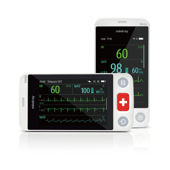
General Product Description Intended for Use The TM80 telemetry monitor is intended for use on Adult and Pediatric patients over three years old to monitor ECG, SpO , NIBP and Resp physiological data. The physiological data can be analyzed, alarmed, stored, reviewed locally on the display of the monitor, and the CentralStation can config and display the physiological parameters from the TM80. -
Page 22: System Components
AP, refer to the user manual of the AP. ■ TM80 The TM80 is the telemetry monitor, used to monitor the patient's ECG, SpO2, NIBP, and Resp physiological data. It relies on the telemetry monitor system to perform normally. ■... -
Page 23: Tm80 Key Features
Central charger ■ Accessories This manual only describes the telemetry monitor main unit (hereinafter called the TM80). For information about the BP10, the central charger, and the central monitoring system, refer to BP10 NIBP Module Operator’s Manual, BeneVision Central Charger Operator’s Manual, and BeneVision Central Monitoring System Operator’s Manual respectively. - Page 24 Pressing this key when the screen lock mode is configured for View Only will display the Screen Locked menu. Display The touch screen is the primary user interface for operating the device and viewing information (or patient data). Alarm light/indicator 2 - 4 BeneVision TM80 Telemetry Monitor Operator’s Manual...
-
Page 25: Tm80 Touch Screen Display
3.7.1 Understanding the Screen Display Orientation. 2.7.1 Display Screen The main screen displays patient parameters and waveforms. A typical display screen is shown below. BeneVision TM80 Telemetry Monitor Operator’s Manual 2 - 5... - Page 26 Mindray Patient Area Network (herein abbreviated as MPAN) indicator ◆ indicates that the telemetry monitor is not paired with the BP10 or one telemetry monitor is not connected to another telemetry monitor for configuration transfer. 2 - 6 BeneVision TM80 Telemetry Monitor Operator’s Manual...
-
Page 27: On-Screen Keyboard
For details about the touch screen operations, refer to 3.7 Basic Operations. 2.7.2 On-Screen Keyboard The telemetry monitor uses an on-screen keyboard to enter alphanumeric information, such as the device name and passwords. BeneVision TM80 Telemetry Monitor Operator’s Manual 2 - 7... - Page 28 Accept button: tap to save the settings and exit the keyboard. Space button: tap to input a space. Alphabetic switch button: tap to switch to the alphabetic layout. More punctuation buttons: tap to display the punctuation keyboard, as shown below. 2 - 8 BeneVision TM80 Telemetry Monitor Operator’s Manual...
- Page 29 BeneVision TM80 Telemetry Monitor Operator’s Manual 2 - 9...
- Page 30 This page intentionally left blank. 2 - 10 BeneVision TM80 Telemetry Monitor Operator’s Manual...
-
Page 31: Getting Started
• Contact Mindray to relocate the telemetry monitor. • Only Mindray authorized personnel can update the telemetry monitor. BeneVision TM80 Telemetry Monitor Operator’s Manual 3 - 1... -
Page 32: Unpacking And Checking
When the device is moved from one place to another, condensation may occur as a result of temperature or humidity difference. In this case, never start the system before the condensation disappears. 3 - 2 BeneVision TM80 Telemetry Monitor Operator’s Manual... -
Page 33: Connecting The Ecg Leadwire
Align the ECG leadwire plug with the ECG connector as indicated by the arrow in the following figure. Insert the ECG leadwire plug into the ECG connector as shown in the enlarged figure below. BeneVision TM80 Telemetry Monitor Operator’s Manual 3 - 3... - Page 34 Do not use the ECG leadwire to move or lift the telemetry monitor. This may cause the device to fall, which may damage the equipment or injure the patient. NOTE • Insert the SpO cap in the SpO connector when SpO is not in use. 3 - 4 BeneVision TM80 Telemetry Monitor Operator’s Manual...
-
Page 35: Installing The Batteries
Installing the Batteries You can use AA batteries or a lithium-ion rechargeable battery pack to power the TM80. The runtime is dependent on the battery configuration chosen. A lithium-ion battery pack will provide the longest runtime. For details about the recommended AA batteries, refer to 18.4 Miscellaneous. -
Page 36: Installing The Aa Batteries
Align the hook on the upper part of the battery tray with the slot on the battery com- partment, as indicated by the enlarged part in the following figure. 3 - 6 BeneVision TM80 Telemetry Monitor Operator’s Manual... -
Page 37: Powering On The Unit
When the telemetry monitor is turned on the next time, the device will prompt whether it is a new patient. Select Yes or No as desired. If the device is a lock mode, a passcode is required. BeneVision TM80 Telemetry Monitor Operator’s Manual 3 - 7... -
Page 38: Understanding Touch Gestures
This section describes the basic operations for the telemetry monitor. WARNING • Patients should be instructed not to interact with the display of the device and to not open the battery compartment while the telemetry monitor is in use. 3 - 8 BeneVision TM80 Telemetry Monitor Operator’s Manual... -
Page 39: Understanding The Screen Display Orientation
: this button is displayed in landscape orientation. It switches landscape display inversely. ◆ : this button is displayed in landscape orientation. It switches landscape display to portrait display. Select the desired button. BeneVision TM80 Telemetry Monitor Operator’s Manual 3 - 9... -
Page 40: Displaying The Quick Keys Area
12.5 Quick Keys Menu. 3.7.5 Entering the Main Menu Press the key to enter the main menu. The main menu allows access to most of the system functions and settings. 3 - 10 BeneVision TM80 Telemetry Monitor Operator’s Manual... -
Page 41: Turning The Display Off
■ If the touch screen is not touched for the configured Display Auto Off time, then the screen will turn off after the configured Display Auto Off time has elapsed. BeneVision TM80 Telemetry Monitor Operator’s Manual 3 - 11... -
Page 42: Turning The Display On
Once the passcode is entered the screen is temporarily unlocked. If the pressed or the device times out, the screen will lock again and a passcode must be entered. For details about setting the screen lock, refer to 12.8 Screen Lock Menu. 3 - 12 BeneVision TM80 Telemetry Monitor Operator’s Manual... -
Page 43: Acknowledging The Nurse Call
To acknowledge the triggered nurse call, tap Attendant Present in the main menu. The “Nurse Call Cancelled” message will display in the message area. For details about how to trigger a nurse call, refer to 2.6 TM80 Physical View. WARNING •... - Page 44 While using a pouch with the telemetry monitor on the patient, consider the patient’s condition. Be careful about the placement of the straps, as the straps could present a strangulation hazard. 3 - 14 BeneVision TM80 Telemetry Monitor Operator’s Manual...
-
Page 45: Securing Pouches For The Telemetry Monitor And Bp10
NOTE • Do not secure the pouches for the telemetry monitor and BP10 on the same side of the patient’s body. Wearing the disposable pouches BeneVision TM80 Telemetry Monitor Operator’s Manual 3 - 15... - Page 46 This page intentionally left blank. 3 - 16 BeneVision TM80 Telemetry Monitor Operator’s Manual...
-
Page 47: User Configurations
In the Portrait section of the Display Setup menu, tap Rows. Three options display: 2, 3, and 4. Tap an option to set the row numbers. The selected option displays to the right of Rows. BeneVision TM80 Telemetry Monitor Operator’s Manual 4 - 1... -
Page 48: Understanding Landscape Orientation Display Rules
Drag the selected parameter or waveform to the desired position, and then release it. Repeat steps 4 and 5 until the desired order is configured. Tap the icon to exit the Landscape Order menu. 4 - 2 BeneVision TM80 Telemetry Monitor Operator’s Manual... -
Page 49: Setting The Display Brightness
It indicates that the alarm sound is turned off. • When your telemetry monitor is connected to the CMS and Sounds is turned off, Sounds automatically changes to 2 if the CMS is disconnected. BeneVision TM80 Telemetry Monitor Operator’s Manual 4 - 3... - Page 50 This page intentionally left blank. 4 - 4 BeneVision TM80 Telemetry Monitor Operator’s Manual...
-
Page 51: Patient Management
Select the desired option. The “Are you sure you want to change the patient category?” message displays. Select Yes to confirm the change. The selected patient category displays to the right of Patient Category. BeneVision TM80 Telemetry Monitor Operator’s Manual 5 - 1... -
Page 52: Changing The Paced Status
When the telemetry monitor is connected to the CMS, the patient category at the CMS is updated if the patient category is changed at the telemetry monitor. Refer to BeneVision Central Monitoring System Operator’s Manual for details. 5.3.3 Changing the Paced Status It is important to correctly set the patient’s paced status before patient monitoring. -
Page 53: Changing The Department Name, Room Number, And Bed Number
After a telemetry monitor is connected to the CMS, when it enters or exits Standby mode, the CMS is also notified to enter or exit Standby mode. Refer to BeneVision Central Monitoring System Operator’s Manual for details. To enter the Standby mode: In the main menu, tap Standby. -
Page 54: Exiting The Standby Mode
When the telemetry monitor is connected to a CMS, the patient being discharged from the telemetry monitor is also discharged from the CMS. Refer to BeneVision Central Monitoring System Operator’s Manual for details. 5.6.1 Selecting the Discharge Patient Menu To discharge a patient via the Discharge Patient menu, follow this procedure: Enter the Discharge Patient menu in either of the following ways: ◆... -
Page 55: Restarting The Telemetry Monitor
The device prompts whether this is a new patient or not. Select Yes if this is a new patient. Select Yes when asked to confirm that the discharge should begin. BeneVision TM80 Telemetry Monitor Operator’s Manual 5 - 5... - Page 56 This page intentionally left blank. 5 - 6 BeneVision TM80 Telemetry Monitor Operator’s Manual...
-
Page 57: Alarms
If the telemetry monitor is connected to the CMS, alarms can be presented and controlled at the CMS. Remote suspension or reset of alarms at the CMS may cause a potential hazard. For more information, refer to BeneVision Central Monitoring System Operator’s Manual. -
Page 58: Understanding The Alarms
Alarm Alarm Alarm Alarm lamp Yellow Cyan None None Flashing Flashing flashing frequency: frequency: 1.4Hz - 0.4Hz -0.8 Duty cycle: 2.8 Hz Duty cycle: 100% on Duty cycle: 20% -60% 20%-60% 6 - 2 BeneVision TM80 Telemetry Monitor Operator’s Manual... - Page 59 Parameter value White text Black text Black text None None inside a inside a inside a flashing flashing red flashing yellow box cyan box BeneVision TM80 Telemetry Monitor Operator’s Manual 6 - 3...
-
Page 60: Alarm Status Symbols
Changing Alarm Settings You can change alarm properties for parameters collectively or individually. To change alarm properties, follow this procedure: Enter the Alarm Limit menu in either of the following ways: 6 - 4 BeneVision TM80 Telemetry Monitor Operator’s Manual... -
Page 61: Changing The Alarm Volume
Limits menu. If not, you can adjust them manually. These alarm limits will remain unchanged until you select auto limits again or adjust them manually. The telemetry monitor calculates auto limits basing on the following rules: BeneVision TM80 Telemetry Monitor Operator’s Manual 6 - 5... -
Page 62: Restoring Default Alarm Settings
Swipe your finger up at the bottom of the main screen to display the quick keys area. Tap Alarm Pause. When alarms are paused, the following indicators are given: ■ No physiological alarm will be presented within the alarm pause time. 6 - 6 BeneVision TM80 Telemetry Monitor Operator’s Manual... -
Page 63: Resetting Alarms
The alarm pause time is two minutes by default. You can change the alarm pause time at the CMS. For details, refer to BeneVision Central Monitoring System Operator’s Manual. When the pause time expires, the alarm paused status is automatically deactivated. -
Page 64: Resetting Technical Alarms
NOTE • Latching settings for physiological alarms are configured at the CMS. For more information on how to configure latching settings, refer to BeneVision Central Monitoring System Operator’s Manual. Actions When an Alarm Occurs When an alarm occurs, observe the following steps and take proper actions: Check the patient’s condition. - Page 65 Make sure the alarm condition is corrected. For more information, refer to 15 Troubleshooting. BeneVision TM80 Telemetry Monitor Operator’s Manual 6 - 9...
- Page 66 This page intentionally left blank. 6 - 10 BeneVision TM80 Telemetry Monitor Operator’s Manual...
-
Page 67: Monitoring Ecg, Arrhythmia, St And Qt
QRS complexes. Preparation for Monitoring ECG CAUTION • Interference from a non-grounded instrument near the patient and electro- surgery interference can cause problems with the waveform. BeneVision TM80 Telemetry Monitor Operator’s Manual 7 - 1... -
Page 68: Preparing The Patient's Skin
Prepare the electrode site with alcohol only if the skin is extremely greasy. If alcohol is used as a drying agent, always allow the skin to dry before placing the electrode on the skin. 7 - 2 BeneVision TM80 Telemetry Monitor Operator’s Manual... -
Page 69: Positioning The Electrodes
Consult the electrode manufacturer’s instructions for specific use. Ensure all the electrodes are applied to the patient properly. Secure the lead wires to the patient according to hospital practice. BeneVision TM80 Telemetry Monitor Operator’s Manual 7 - 3... -
Page 70: Configuring The Ecg Lead Labeling
Tap any area in the ECG waveform or parameter area to call up the ECG menu. Set Cable Type to 3 Lead, 5 Lead, 6 Lead, or Auto according to your requirement. 7 - 4 BeneVision TM80 Telemetry Monitor Operator’s Manual... -
Page 71: Placing The Electrodes
A 5-wire lead set can monitor seven ECG vectors (I, II, III, aVR, aVL, aVF, and V) simultaneously. The recommended 5-wire lead placement is as follows: RA (R) LA (L) V(C) LL (F) RL (N) BeneVision TM80 Telemetry Monitor Operator’s Manual 7 - 5... - Page 72 The positions of Va (Ca) and Vb (Cb) can also be placed at a proper position according to the clinician’s needs. RA (R) LA (L) V6 (C6) V1 (C1) V5 (C5) V4 (C4) LL (F) RL (N) V2 (C2) V3(C3) 7 - 6 BeneVision TM80 Telemetry Monitor Operator’s Manual...
- Page 73 C4 (white) In the fifth intercostal space, mid-clavicular line. V5 (brown) C5 (white) In the fifth intercostal space, anterior axillary line. V6 (brown) C6 (white) In the fifth intercostal space, mid-axillary line. BeneVision TM80 Telemetry Monitor Operator’s Manual 7 - 7...
- Page 74 RA (R) LA (L) LL (F) 3-wire lead placement for a pacemaker patient (AHA)/(IEC) Pacemaker RA (R) LA (L) V(C) LL (F) RL (N) 5-wire Lead Placement for a Pacemaker Patient (AHA)/(IEC) 7 - 8 BeneVision TM80 Telemetry Monitor Operator’s Manual...
-
Page 75: Checking The Lead Placement
Enter the Lead Placement menu in either of the following ways: ■ Tap the ECG lead off message in the prompt message area of the main screen. key to enter the main menu → tap Lead Placement. ■ Press the BeneVision TM80 Telemetry Monitor Operator’s Manual 7 - 9... -
Page 76: Checking The Paced Status
In the Pacer section, check if Paced is appropriate for the patient. If it is not correct, tap Paced and select the correct paced status. For details about the options, refer to 5.3.3 Changing the Paced Status. 7 - 10 BeneVision TM80 Telemetry Monitor Operator’s Manual... -
Page 77: Maintaining Quality Ecg Signal
Auto, 3 Lead, 5 Lead, 6 Lead Refer to 7.4.3 ECG Leadwire Types for details. Smart Lead Refer to 7.4.3 ECG Leadwire Types for details. (Monitored Lead) The factory default settings are in bold. BeneVision TM80 Telemetry Monitor Operator’s Manual 7 - 11... -
Page 78: Ecg Leadwire Types
Vb options: Vb, V1, V2, V3, V4, V5, V6. Vb is the default. 7.4.4 Configuring ECG Waveforms To configure ECG waveforms, follow this procedure: In the Waveform section of the ECG menu, select the options described in the fol- lowing table. 7 - 12 BeneVision TM80 Telemetry Monitor Operator’s Manual... -
Page 79: Configuring The Pacer
Pacer Reject Selects whether or not to reject the On, Off pace pulses. The factory default settings are in bold. Tap the icon to exit the ECG menu. BeneVision TM80 Telemetry Monitor Operator’s Manual 7 - 13... -
Page 80: Configuring The Ecg Waveform Size
The factory default settings are in bold. 7.4.8 Configuring the Notch Filter Notch filter filters out AC line noise from the ECG waveform. Refer to 12.3 Configuring the General Menu for details. 7 - 14 BeneVision TM80 Telemetry Monitor Operator’s Manual... -
Page 81: Configuring The Hr Alarm Source
HR/PR alarm off symbol: when HR/PR alarm is switched on and valid HR/PR value is detected, HR/PR alarm high and low limits in place of the alarm off symbol are dis- played. NOTE BeneVision TM80 Telemetry Monitor Operator’s Manual 7 - 15... -
Page 82: About The Hr Digital Area
The ECG waveform area scrolls the waveform at the configured sweep speed. ■ The ECG waveform area indicates a Pacer indicator when a pace pulse is detected and Paced is enabled. 7 - 16 BeneVision TM80 Telemetry Monitor Operator’s Manual... -
Page 83: Arrhythmia Monitoring
This section lists all arrhythmia events and their criteria. 7.7.2.1 Lethal Arrhythmia Events Arrhythmia message Description Asystole No QRS complex detected within the set time interval in the absence of ventricular fibrillation or chaotic signal. BeneVision TM80 Telemetry Monitor Operator’s Manual 7 - 17... - Page 84 No QRS complex detected for 300 ms following a pace pulse (for paced patients only). Pacer Not Pacing No pace pulse detected for 1.75 x average R-to-R intervals following a QRS complex (for paced patients only). 7 - 18 BeneVision TM80 Telemetry Monitor Operator’s Manual...
-
Page 85: Changing Arrhythmia Alarm Settings
CMS. ◆ Lethals Only: switches on all the lethal arrhythmia alarms only. Other types of arrhythmia alarms are off. In the Alarms section, select the options described in the following table. BeneVision TM80 Telemetry Monitor Operator’s Manual 7 - 19... - Page 86 V-Tach PVCs: 3 beats to 99 beats; the default is 6 beats. V-Tach Rate:100 bpm~200 bpm; the default is 130 bpm. Alarm priority: High The factory default settings are in bold. 7 - 20 BeneVision TM80 Telemetry Monitor Operator’s Manual...
- Page 87 Multif PVCs Window: 3 beats to 31 beats; the default is 15 beats. Alarm priority: Prompt, Low, Med, High On, Off Alarm priority: Prompt, Low, Med, High The factory default settings are in bold. BeneVision TM80 Telemetry Monitor Operator’s Manual 7 - 21...
- Page 88 Vent Rhythm On, Off Alarm priority: Prompt, Low, Med, High Pause On, Off Pause Time: 1.5s, 2.0s, 2.5s, 3.0s Alarm priority: Prompt, Low, Med, High The factory default settings are in bold. 7 - 22 BeneVision TM80 Telemetry Monitor Operator’s Manual...
- Page 89 “Lethal Arrhys Off” message. The ECG waveform area on the screen of the CMS displays Asystole, V-Fib/V-Tach, or V- Tach Off depending on the actual lethal arrhythmia alarm. BeneVision TM80 Telemetry Monitor Operator’s Manual 7 - 23...
-
Page 90: Intelligent Arrhythmia Alarm
You can set the arrhythmia alarm timeout period at the CMS. For how to configure the arrhythmia alarm timeout period, refer to 13.7.2 Configuring the Arrhythmia Shield Time. NOTE 7 - 24 BeneVision TM80 Telemetry Monitor Operator’s Manual... -
Page 91: Understanding The Arrhythmia Display
Parameter label PVCs per minute label PVCs per minute value Pauses per minute label Pauses per minute value ST Segment Monitoring ST segment analysis is intended for adult and pediatric patients. BeneVision TM80 Telemetry Monitor Operator’s Manual 7 - 25... -
Page 92: St Safety Information
Numerics displayed in the ST digital area are different according to the lead type: ■ When the 3-lead ECG leadwires are used, the ST digital area is not displayed. A ST value is displayed in the HR digital area. 7 - 26 BeneVision TM80 Telemetry Monitor Operator’s Manual... -
Page 93: Configuring St Alarm Settings
Relative: it is the default option. You can set the alarm properties for ST Single and ST Dual alarms. In the Alarms section, select the options described in the following table. BeneVision TM80 Telemetry Monitor Operator’s Manual 7 - 27... -
Page 94: Qt/Qtc Interval Monitoring
QT interval. Therefore, several formulas can be used to correct the QT interval for heart rate. The heart rate corrected QT interval is abbreviated as QTc. QT/QTc interval monitoring is intended for adult and pediatric patients. 7 - 28 BeneVision TM80 Telemetry Monitor Operator’s Manual... -
Page 95: Qt/Qtc Monitoring Limitations
QT function. To do so, follow this procedure: On the main screen, tap the HR digital area or ECG waveform area to enter the ECG menu. In the Parameter Setup section, tap QT/QTc. Switch on QT Analysis. NOTE BeneVision TM80 Telemetry Monitor Operator’s Manual 7 - 29... -
Page 96: Displaying Qt/Qtc Numerics And Segments
200 ms to 800ms; the step is 1ms. The default is 500 for adult and the default is 480 for pediatric. Alarm priority: Low, Med, High The factory default settings are in bold. 7 - 30 BeneVision TM80 Telemetry Monitor Operator’s Manual... -
Page 97: Relearning
If you suspect that false arrhythmia alarms are presented, you may need to manually initiate an ECG relearn. To do so, follow this procedure: On the main screen, tap the QT digital area to enter the QT/QTc menu. BeneVision TM80 Telemetry Monitor Operator’s Manual 7 - 31... - Page 98 ECG signal is relatively noise-free. If ECG learning takes place during arrhythmias, the ectopic beats may be incorrectly learned as normal QRS complexes. This may result in missed detection of subsequent arrhythmia events. 7 - 32 BeneVision TM80 Telemetry Monitor Operator’s Manual...
-
Page 99: Monitoring Respiration (Resp) (Optional)
CAUTION • Only use parts and accessories specified in this manual. • Respiration monitoring is not for use on the patients who are very active, as this will cause false alarms. BeneVision TM80 Telemetry Monitor Operator’s Manual 8 - 1... -
Page 100: Preparation For Monitoring Resp
ECG electrode placement is applied, the two electrodes should be RA and LL of ECG Lead II. For more information, refer to 7.3.4.1 Standard 3-Leadwire Electrode Placement.. RA (R) LL (F) Lead II 8 - 2 BeneVision TM80 Telemetry Monitor Operator’s Manual... -
Page 101: Changing Resp Settings
When the Resp functionality is enabled, you can enter the Resp menu in either of the following ways: ■ On the main screen, tap the Resp digital area or waveform area. BeneVision TM80 Telemetry Monitor Operator’s Manual 8 - 3... -
Page 102: Configuring The Resp Setup
8.4.5 Configuring Resp Alarm Settings To configure Resp alarm settings, follow this procedure: In the Alarms section of the Resp menu, tap Resp Alarm Setup . Select the options described in the following table. 8 - 4 BeneVision TM80 Telemetry Monitor Operator’s Manual... -
Page 103: Understanding The Resp Display
After tapping this option, you can configure the alarm priority. The factory default settings are in bold. Understanding the Resp Display 8.5.1 Resp Digital Area Parameter name Measurement unit Respiration rate (RR) BeneVision TM80 Telemetry Monitor Operator’s Manual 8 - 5... -
Page 104: About The Resp Digital Area
8.5.4 About the Resp Waveform Area ■ The Resp waveform, lead label, and waveform gain display in the configured Resp color. ■ The Resp waveform area scrolls the waveform at the configured sweep speed. 8 - 6 BeneVision TM80 Telemetry Monitor Operator’s Manual... -
Page 105: Monitoring Pulse Oxygen Saturation (Spo2) (Optional)
The MS board pulse oximeter can be used during defibrillation, but the readings may be inaccurate for a short time. Measurement Limitations The following factors may influence the accuracy of SpO measurement: Patient physiological characteristics: ■ ◆ Cardiac arrest ◆ Hypotension BeneVision TM80 Telemetry Monitor Operator’s Manual 9 - 1... - Page 106 Arterial catheters and intra-aortic balloon Others ■ ◆ Inappropriate positioning of the SpO sensor, or use of incorrect SpO sensor ◆ Cuff or arterial blood pressure measurement device on the same limb as the sensor. 9 - 2 BeneVision TM80 Telemetry Monitor Operator’s Manual...
-
Page 107: Safety
Check accessory compatibility prior to use. Incompatible accessories may degrade the device’s performance and may cause harm to the patient. • Do not use disposable SpO sensor for multiple times. Otherwise, inaccurate measurement may occur. BeneVision TM80 Telemetry Monitor Operator’s Manual 9 - 3... -
Page 108: Connecting The Spo2 Module
Connecting the SpO Module Connect the SpO module to the telemetry monitor. The telemetry monitor can auto detect the SpO module type when the SpO module is connected. 9 - 4 BeneVision TM80 Telemetry Monitor Operator’s Manual... - Page 109 Connecting the Masimo SpO module BeneVision TM80 Telemetry Monitor Operator’s Manual 9 - 5...
- Page 110 ■ On the main screen, tap the SpO digital area or SpO waveform area. key to enter the main menu → tap Parameter Setup → select SpO ■ Press the 9 - 6 BeneVision TM80 Telemetry Monitor Operator’s Manual...
- Page 111 This mode is useful for patients that are at particular risk of the sensor becoming detached (pediatric, combative, etc.) The factory default settings are in bold. BeneVision TM80 Telemetry Monitor Operator’s Manual 9 - 7...
- Page 112 When using the High Sensitivity setting, performance of the "Sensor Off" detection may be compromised. If the device is in this setting and the sensor becomes dislodged from the patient, the potential for false readings may occur 9 - 8 BeneVision TM80 Telemetry Monitor Operator’s Manual...
- Page 113 Desat alarm properties. You can also set whether to measure SpO and NIBP simultaneously. In the Alarms section of the SpO menu, select the options described in the follow- ing table. BeneVision TM80 Telemetry Monitor Operator’s Manual 9 - 9...
- Page 114 SpO module. ■ Masimo SpO module is with a logo of Masimo SET. ■ Nellcor SpO module is with a logo of Nellcor. 9 - 10 BeneVision TM80 Telemetry Monitor Operator’s Manual...
-
Page 115: Applying The Sensor
If the sensor is too tight because the application site is too large or becomes too large due to edema, excessive pressure for prolonged periods may result in venous congestion distal from the application site, leading to interstitial edema and tissue ischemia. BeneVision TM80 Telemetry Monitor Operator’s Manual 9 - 11... -
Page 116: Understanding The Spo2 Display
PR value Pulse rate (PR) label Alarm high limit and low limit.When SpO alarm is switched off, the activation state off icon instead of alarm limits is displayed. Masimo SpO digital area 9 - 12 BeneVision TM80 Telemetry Monitor Operator’s Manual... - Page 117 Signal Index Quality (SIQ) Area name Pleth waveform Masimo SpO waveform area (SIQ enabled) Nellcor SpO waveform area 9.7.4 About the SpO Waveform Area ■ Displays in the configured SpO color. BeneVision TM80 Telemetry Monitor Operator’s Manual 9 - 13...
-
Page 118: Masimo Information
Possession or purchase of this device does not convey any express or implied license to use the device with unauthorized replacement parts which would, alone, or in combination with this device, fall within the scope of one or more of the patents relating to this device. 9 - 14 BeneVision TM80 Telemetry Monitor Operator’s Manual... -
Page 119: Monitoring Noninvasive Blood Pressure (Nibp) (Optional)
If not, repeat Steps 1 to 4. In the list of devices, select your desired device and tap Connect. Once the device is connected successfully, the status will be changed from Disconnect to Connected. BeneVision TM80 Telemetry Monitor Operator’s Manual 10 - 1... -
Page 120: System Responses After Successful Pairing
Besides, NIBP measurement for the patient monitored by BP10 will stop and the data history related to this patient will be cleared at BP10. When a BP10 in ABPM mode is not unpaired with a telemetry monitor and needs to be paired 10 - 2 BeneVision TM80 Telemetry Monitor Operator’s Manual... -
Page 121: Unpairing The Telemetry Monitor With The Bp10
The status of the BP10 unpaired will be displayed as Disconnect on the list of Devices at the telemetry monitor. ■ icon will be changed to in the top-right corner of the telemetry monitor’s screen and of the BP10. BeneVision TM80 Telemetry Monitor Operator’s Manual 10 - 3... -
Page 122: Unpairing Via The Bp10
Before admitting a new patient at a BP10, you need to unpair it with a telemetry monitor first. • When the “MPAN Disconnected” message is displayed, medical staff should pay close attention to the patient’s status. 10 - 4 BeneVision TM80 Telemetry Monitor Operator’s Manual... -
Page 123: Screen Display After Pairing A Telemetry Monitor With A Bp10
NIBP measurement history area: displays NIBP measurement history information. 10.5 Interactions after Pairing a Telemetry Monitor with a BP10 10.5.1 Overview of Interactions Once a telemetry monitor is paired successfully with a BP10, the interactions proceed as shown below. BeneVision TM80 Telemetry Monitor Operator’s Manual 10 - 5... -
Page 124: Operating The Bp10 Via The Telemetry Monitor
Tap NIBP STAT to start the series measurement in continuous mode at the BP10. 10.5.3 Configuring NIBP Settings To configure NIBP settings, follow this procedure: In the Setup section of the NIBP menu, select the options described in the following table. 10 - 6 BeneVision TM80 Telemetry Monitor Operator’s Manual... -
Page 125: Configuring Nibp Alarm Settings
Range: 26 to (high limit - 5) Default value: 90 • For pediatric: Range: 26 to (high limit - 5) Default:70 : Med, High Alarm priority The factory default settings are in bold. BeneVision TM80 Telemetry Monitor Operator’s Manual 10 - 7... - Page 126 Range: 16 to (high limit - 5) Default value: 60 • For pediatric: Range: 16 to (high limit - 5) Default: 50 Alarm priority: , High The factory default settings are in bold. 10 - 8 BeneVision TM80 Telemetry Monitor Operator’s Manual...
- Page 127 Range: 10 to (DIA low limit - 5) Default value: 35 • For pediatric: Range: 10 to (DIA low limit - 5) Default: 30 Alarm priority: High The factory default settings are in bold. BeneVision TM80 Telemetry Monitor Operator’s Manual 10 - 9...
- Page 128 SYS Extreme, DIA Extreme, or MAP Extreme. • For systolic pressure, diastolic pressure, or mean pressure, its alarm high limit should beat least 5mmHg greater than its alarm low limit. 10 - 10 BeneVision TM80 Telemetry Monitor Operator’s Manual...
-
Page 129: Review
When you swipe your finger up or down the tabular trends, parameters and their trend data will be automatically moved up or down. The following figure is for reference only. BeneVision TM80 Telemetry Monitor Operator’s Manual 11 - 1... - Page 130 Highlighted column: indicates the trend data currently selected. Search button: allows searching trend data within the specific time range. Next page button: tapping this button moves to the right-most column of the review page. 11 - 2 BeneVision TM80 Telemetry Monitor Operator’s Manual...
-
Page 131: Example Tabular Trends Data Search Page
Slider: indicates the position of current window time in the entire time length. Drag- ging the slider left or right enables you to locate the trend data at a specific time and also refreshes trend data in current window accordingly. BeneVision TM80 Telemetry Monitor Operator’s Manual 11 - 3... -
Page 132: Changing The Resolution Of Trend Data
Option 1: Press the key to enter the main menu. Tap Review. Tap Events. Option 2: Tap the Events button in the upper right corner of the tabular trends review page. 11 - 4 BeneVision TM80 Telemetry Monitor Operator’s Manual... -
Page 133: Example Events Review Page
Different color blocks are displayed on the left of each event to indicate different event types. For the meaning of each color block, refer to 11.2.2 Example Tabular Trends Review Page. BeneVision TM80 Telemetry Monitor Operator’s Manual 11 - 5... -
Page 134: Example Event Details Page
You can view these numerics by swiping your finger at the bottom of the main screen. The background color of numerics indicates the alarm priority. ■ Red: high priority alarm event ■ Yellow: medium priority alarm event ■ Cyan: low priority alarm event 11 - 6 BeneVision TM80 Telemetry Monitor Operator’s Manual... - Page 135 If you wish to return to the event list, tap the icon. BeneVision TM80 Telemetry Monitor Operator’s Manual 11 - 7...
- Page 136 This page intentionally left blank. 11 - 8 BeneVision TM80 Telemetry Monitor Operator’s Manual...
-
Page 137: Configuring The Telemetry Monitor
Changes the ECG lead labeling. AHA, IEC Calibrate ECG Enables or disables the ECG On, Off verification. Refer to 17.6 Verifying the ECG for details. The factory default settings are in bold. BeneVision TM80 Telemetry Monitor Operator’s Manual 12 - 1... -
Page 138: Configuring Device Location
Department is the one entered in the Department field of the Device Location menu. ◆ Unfixed: you can modify Department in the Patient Info menu. Tap Bed No./Room No. Select the desired option. 12 - 2 BeneVision TM80 Telemetry Monitor Operator’s Manual... -
Page 139: Configuring The Alarms Menu
Allows an authorized user to enable or On, Off disable the reminder tone. If the alarm sound is turned off, enabling this setting can issue a periodic reminder tone. The factory default settings are in bold. BeneVision TM80 Telemetry Monitor Operator’s Manual 12 - 3... - Page 140 Be careful when turning off the alarm sound. • Do not rely exclusively on the audible alarm system for monitoring. Adjustment of alarm volume to a low level may result in a hazard to the patient. 12 - 4 BeneVision TM80 Telemetry Monitor Operator’s Manual...
-
Page 141: Quick Keys Menu
The Quick Keys configuration menu displays. From the quick keys area at the bottom of the screen, tap a quick key you want to configure. A list of options displays. A list of options BeneVision TM80 Telemetry Monitor Operator’s Manual 12 - 5... -
Page 142: Deleting A Quick Key
12.6 Configuring the Network Menu In the Network menu, you can configure the network and connect the telemetry monitor to the BeneVision Central Monitoring System via the wireless network. To configure the Network menu: In the Maintenance menu, tap Network. -
Page 143: Configuring Ip Settings
Range: 1 to 255 for the number before the first decimal point 0 to 255 for the number after first decimal point Factory default: 192.168.0.100 The factory default settings are in bold. BeneVision TM80 Telemetry Monitor Operator’s Manual 12 - 7... -
Page 144: Configuring Wlan Settings For Tm80
The factory default settings are in bold. Tap Confirm to apply the settings and exit the IP Address Setup menu. 12.6.2 Configuring WLAN Settings for TM80 In the Network menu, tap WLAN Setup. Select the options described in the following table. -
Page 145: Configuring Connection To The Cms
• We recommend that the latest WPA2-PSK or WPA2 CCKM security mode be used when the TM80 is in use. It provides a strong method of security when used with rotating strong passwords. Besides, it can provide optimal mobility and connectivity performance. -
Page 146: Selecting A Cms
Tap Confirm to apply the settings and exit the Connect CMS menu. 12.6.4 Selecting a CMS When you connect a telemetry monitor to a CMS in unicast mode, you can select a CMS by one of the following ways: 12 - 10 BeneVision TM80 Telemetry Monitor Operator’s Manual... -
Page 147: Selecting Wifi Bands And Channels For Tm80
12.6.6 EAP Certificate Management for TM80 You can import up to 10 certificates from a USB drive or delete certificates from the TM80. The TM80 only supports certificates in PEM format. If you need to use certificates in other formats, you need to convert the certificates before importing them into the TM80. -
Page 148: Configuring The Defaults Menu
Network tap EAP Certificate. Tap Local. Select the desired certificate. Tap Delete. 12.7 Configuring the Defaults Menu The Defaults menu allows an authorized user to manage the system configurations. 12 - 12 BeneVision TM80 Telemetry Monitor Operator’s Manual... -
Page 149: Transferring A Configuration
Tap the icon to exit the Defaults menu. 12.7.1 Transferring a Configuration You can copy some configurations of one TM80 to anotherTM80 via the MPAN functionality. The following takes the example of transferring the configurations from TM80 A to TM80 B. -
Page 150: Screen Lock Menu
Upon powering up, the main screen will be displayed after the new patient choice is made. ◆ Main Screen is accessible without passcode entry. ◆ The System Info menu is accessible by tapping the battery symbol on the main screen. 12 - 14 BeneVision TM80 Telemetry Monitor Operator’s Manual... -
Page 151: Setting The Screen Lock
12.10 Changing the Device Name In the Maintenance menu, tap Device Name. Use the on-screen keyboard to input the device name. Tap Accept to save the setting and exit the Device Name menu. BeneVision TM80 Telemetry Monitor Operator’s Manual 12 - 15... -
Page 152: Auto Enter Monitor Mode
CMS. The configuration is synchronized to the telemetry monitor. • The telemetry monitor switches back to telemetry mode only when all the abnormal conditions that trigger auto enter monitor mode disappear. 12 - 16 BeneVision TM80 Telemetry Monitor Operator’s Manual... -
Page 153: Using With A Patient Monitor
Press the main menu button on the front panel of the telemetry. If prompted, input the password for the screen lock dialog. When Screen Lock is set to Off, skip this step. Select Unpair. BeneVision TM80 Telemetry Monitor Operator’s Manual 12 - 17... -
Page 154: Service Menu
12.13 Demo Mode Allows an authorized user to choose a demonstration mode for in-servicing staff or testing product features. 12.14 Service Menu Allows an authorized user access to the passcode protected Service menu. 12 - 18 BeneVision TM80 Telemetry Monitor Operator’s Manual... -
Page 155: Monitoring With The Telemetry Monitor At The Cms
They will be automatically loaded when a patient category is changed or a patient is discharged at the telemetry monitor. When the TM80 is disconnected from the CMS and then re-establishes connection to the CMS, it can send the following data which was not received by the CMS during the time of connection loss. -
Page 156: Network Safety Information
RF interference may result in wireless network disconnection. • Ensure that the TM80’s IP address setting is correct. Changing the network settings may result in network disconnection. Contact your service personnel if you have any problems on setting the IP address. -
Page 157: Setting The Analysis Leads
A normal ECG waveform (as shown in the following figure) typically includes a sharp and well defined QRS complexes with consistent spacing between R waves, and an ECG baseline that is free of noise and artifact. BeneVision TM80 Telemetry Monitor Operator’s Manual 13 - 3... -
Page 158: Changing The Qtc Formula
The CMS uses the Hodges correction formula by default to correct the QT interval for heart rate. The QTc formula can be changed in the System Setup menu. For how to change the QTc formula, refer to BeneVision Central Monitoring System Operator’s Manual. 13.5.2 QT View In the QT View menu, you can view a snapshot of the real-time wave and to verify that the QT algorithm detects correct Q and T points. - Page 159 Set an ST baseline when ST values None become stable. The ST template updated time displays at the bottom of the screen. Hide Baseline Hides the reference baseline. None The factory default settings are in bold. BeneVision TM80 Telemetry Monitor Operator’s Manual 13 - 5...
-
Page 160: St Monitoring
Selecting leads that contain the least amount of baseline flutter will improve measurement accuracy, but accurate ST deviation measurement is dependent on the correct location of the ISO and ST points. 13 - 6 BeneVision TM80 Telemetry Monitor Operator’s Manual... -
Page 161: Adjusting St Measurement Points
13.6.2 Entering the ST Graphic Window To enter the ST graphic window, follow this procedure. On the ViewBed screen of the CMS, select the ECG digital area or waveform area to enter the ECG menu. BeneVision TM80 Telemetry Monitor Operator’s Manual 13 - 7... -
Page 162: Entering The St View
Set the desired items. Buttons Description Settings* Set Baseline Set an ST baseline when ST values None become stable. The ST template updated time displays at the bottom of the screen. 13 - 8 BeneVision TM80 Telemetry Monitor Operator’s Manual... -
Page 163: Arrhythmia Monitoring
The following figure illustrates the conditions under which PVC alarms will be generated if V-Tach PVCs is set to 6, V-Tach Rate is set to 130, V-Brady PVCs is set to 5, and V-Brady Rate is set to 40. BeneVision TM80 Telemetry Monitor Operator’s Manual 13 - 9... -
Page 164: Configuring The Arrhythmia Shield Time
13.8 Locating the Telemetry Monitor If the AP information of the TM80 has been imported into the CentralStation, you can view device location information for TM80 telemetry monitors. For details on how to import AP information, see BeneVision Central Monitoring System Operator’s Manual. To view... -
Page 165: Sending A Notification To The Telemetry Monitor
If you need to specify an AP location, enter the desired AP location in the Please input location information field If you wish to select all the locations, select Select All. BeneVision TM80 Telemetry Monitor Operator’s Manual 13 - 11... -
Page 166: Setting Authorization
CMS, the maintenance password of the telemetry monitor will be required. NOTE • User Password permission is only available for changing alarm setup and arrhythmia setup, pause and reset alarms. 13 - 12 BeneVision TM80 Telemetry Monitor Operator’s Manual... -
Page 167: Battery
Replace the battery mmediately once the “Critically Low Battery” alarm message displays. Replace the battery in time once the “Low Battery” alarm message displays. If those conditions are not corrected, device shutdown and BeneVision TM80 Telemetry Monitor Operator’s Manual 14 - 1... - Page 168 • When the telemetry monitor is not powered off, if you remove batteries, patient data measured within one minute before the battery removal will be lost. BeneVision TM80 Telemetry Monitor Operator’s Manual 14 - 2...
-
Page 169: Installing The Battery
Retain the ECG cable and SpO module with the device while removing the battery. Lift up the lithium-ion battery pack or AA battery tray at the bottom of the compart- ment to pop it out. BeneVision TM80 Telemetry Monitor Operator’s Manual 14 - 3... -
Page 170: Charging The Rechargeable Lithium-Ion Battery
Use the central charger to charge the lithium-ion batteries. The central charger can charge 10 lithium-ion batteries at one time. For details about the central charger, refer to BeneVision Central Charger Operator’s Manual. 14 - 4 BeneVision TM80 Telemetry Monitor Operator’s Manual... -
Page 171: Storing The Batteries
14.8 Maintaining the Rechargeable Lithium-ion Battery Take care of the rechargeable lithium-ion battery once you receive a new battery for use. The following table describes the battery maintenance activities and recommended frequency. BeneVision TM80 Telemetry Monitor Operator’s Manual 14 - 5... -
Page 172: Disposing Of The Batteries
Discard the lithium-ion battery in the following situations: ■ The battery has visual signs of damage. ■ The battery fails. ■ The battery is aged and its runtime significantly less than the specification. 14 - 6 BeneVision TM80 Telemetry Monitor Operator’s Manual... -
Page 173: Disposing Of The Aa Batteries
14.9.2 Disposing of the AA Batteries The batteries may be subject to local regulations regarding disposal. Dispose of batteries in approved containers. Follow local regulations, if any, to recycle the batteries. BeneVision TM80 Telemetry Monitor Operator’s Manual 14 - 7... - Page 174 This page intentionally left blank. 14 - 8 BeneVision TM80 Telemetry Monitor Operator’s Manual...
-
Page 175: Troubleshooting
The following table lists the problems that are likely to occur. If the problem persists after corrective actions have been taken, contact your service personnel. For methods to troubleshoot the central charger, refer to BeneVision Central Charger Operator’s Manual. For methods to troubleshoot the BP10, refer to BP10 NIBP Module Operator’s Manual. - Page 176 Severe interference occurs in occasionally. some areas. The signal strength is weak some areas. All the telemetry Partial wired network is not configured properly. monitors are offline Wireless interference occasionally. 15 - 2 BeneVision TM80 Telemetry Monitor Operator’s Manual...
-
Page 177: Physiological Alarm Messages At The Telemetry Monitor
The asterisk (*) means the alarm priority is configurable. XX is the ECG lead name BeneVision TM80 Telemetry Monitor Operator’s Manual 15 - 3... - Page 178 Missed Beats Prompt* Nonsus V-Tach Med* Vent Rhythm Pause Low* Irr Rhythm Prompt* A-Fib PVCs/min Med* Pauses/min The asterisk (*) means the alarm priority is configurable. XX is the ECG lead name 15 - 4 BeneVision TM80 Telemetry Monitor Operator’s Manual...
- Page 179 The asterisk (*) means the alarm priority is configurable. XX is the ECG lead name BeneVision TM80 Telemetry Monitor Operator’s Manual 15 - 5...
- Page 180 Resp Artifact The patient’s heartbeat has interfered with his respiration. The asterisk (*) means the alarm priority is configurable. XX is the ECG lead name 15 - 6 BeneVision TM80 Telemetry Monitor Operator’s Manual...
- Page 181 NIBP-D Low above the high alarm limit or fallen below the low alarm limit. The asterisk (*) means the alarm priority is configurable. XX is the ECG lead name BeneVision TM80 Telemetry Monitor Operator’s Manual 15 - 7...
-
Page 182: Technical Alarm Messages At The Telemetry Monitor
B: The technical alarm will be changed to the prompt message, it will not longer make sound or be indicated by the alarm light. ■ C: The technical alarms are cleared, there will be no alarm indications. 15 - 8 BeneVision TM80 Telemetry Monitor Operator’s Manual... - Page 183 There is a service personnel. problem with communications between the module and the telemetry monitor. The asterisk (*) means the alarm priority is configurable. XX is the ECG lead name. BeneVision TM80 Telemetry Monitor Operator’s Manual 15 - 9...
- Page 184 Reposition or contact is poor. replace the electrodes if necessary. The asterisk (*) means the alarm priority is configurable. XX is the ECG lead name. 15 - 10 BeneVision TM80 Telemetry Monitor Operator’s Manual...
- Page 185 Incompatible or Use specified Sensor an unspecified sensors. Incompati sensor is used. The asterisk (*) means the alarm priority is configurable. XX is the ECG lead name. BeneVision TM80 Telemetry Monitor Operator’s Manual 15 - 11...
- Page 186 The measured Contact Mindray Overrange PR value exceeds or your service personnel. measurement range. The asterisk (*) means the alarm priority is configurable. XX is the ECG lead name. 15 - 12 BeneVision TM80 Telemetry Monitor Operator’s Manual...
- Page 187 NIBP module. • There is a problem with communicati on between the telemetry monitor and BP10. The asterisk (*) means the alarm priority is configurable. XX is the ECG lead name. BeneVision TM80 Telemetry Monitor Operator’s Manual 15 - 13...
- Page 188 NIBP Cuff The NIBP airway Check the airway Overpress may be and measure occluded. again. The asterisk (*) means the alarm priority is configurable. XX is the ECG lead name. 15 - 14 BeneVision TM80 Telemetry Monitor Operator’s Manual...
- Page 189 Contact your service personnel. Overrange NIBP value is not within the NIBP-D measurement Overrange range. NIBP-M Overrange The asterisk (*) means the alarm priority is configurable. XX is the ECG lead name. BeneVision TM80 Telemetry Monitor Operator’s Manual 15 - 15...
- Page 190 The lithium-ion Error battery communication error occurred. Battery The battery Type Error contacts are in bad contact. The asterisk (*) means the alarm priority is configurable. XX is the ECG lead name. 15 - 16 BeneVision TM80 Telemetry Monitor Operator’s Manual...
- Page 191 Failed default configuration. Loading An error Defaults occurred while Failed loading the default configuration. The asterisk (*) means the alarm priority is configurable. XX is the ECG lead name. BeneVision TM80 Telemetry Monitor Operator’s Manual 15 - 17...
- Page 192 This page intentionally left blank. 15 - 18 BeneVision TM80 Telemetry Monitor Operator’s Manual...
-
Page 193: Cleaning And Disinfecting
Check the equipment after cleaning and disinfecting. If there is any sign of damage, remove it from use. • Be sure to disconnect all power cables from the outlets before cleaning the equipment. BeneVision TM80 Telemetry Monitor Operator’s Manual 16 - 1... -
Page 194: Cleaning And Disinfecting The Equipment
0.105%, n-Alkyl dimethyl ethylbenzyl ammonium chlorides 0.105% ® Rely+On Virkon Powder * Powder Used as 1% solution (Used as 1% solution) Biocidal active: Pentapotassium bis (peroxymonosulphate) bis (sulphate)(500g/kg), Contains dipotassium peroxodisulphate. 16 - 2 BeneVision TM80 Telemetry Monitor Operator’s Manual... - Page 195 ® PDI Super Sani-Cloth n-Alkyl dimethyl ethylbenzyl Germicidal Disposable Wipe * ammonium chlorides 0.25%, n-Alkyl dimethyl benzyl ammonium chlorides 0.25%, Isopropyl Alcohol 55.0%, VIRAGUARD Hospital Surface Isopropanol 70%,Other ingredients 30% Disinfectants BeneVision TM80 Telemetry Monitor Operator’s Manual 16 - 3...
-
Page 196: Cleaning The Equipment
Shut down the device. Clean the display screen with wipes or a soft cloth moistened with one of the clean- ing agents listed in 16.3.1 Approved Cleaning and Disinfecting Agents only. 16 - 4 BeneVision TM80 Telemetry Monitor Operator’s Manual... -
Page 197: Disinfecting The Equipment
Never allow the disinfectants to spill or enter the plug, connector or battery compartment. If liquid has accidentally entered the equipment or its parts, shut down the equipment and have the device serviced by authorized service personnel. BeneVision TM80 Telemetry Monitor Operator’s Manual 16 - 5... -
Page 198: Cleaning And Disinfecting Other Parts
Clean and disinfect other parts with a soft cloth moistened with alcohol. During cleaning and disinfection, always avoid metallic objects. Wipe off the alcohol residue with a dry cloth. Dry these parts in a ventilated, cool place. CAUTION 16 - 6 BeneVision TM80 Telemetry Monitor Operator’s Manual... -
Page 199: Sterilization
Product discoloration ■ Metal part corrosion ■ Brittle and breaking wires, connectors, and equipment housing ■ Reduced cable and leadwire life ■ Overall system performance degradation ■ Equipment malfunction or failure BeneVision TM80 Telemetry Monitor Operator’s Manual 16 - 7... - Page 200 This page intentionally left blank. 16 - 8 BeneVision TM80 Telemetry Monitor Operator’s Manual...
-
Page 201: Maintenance
If you discover a problem with any of the equipment, contact your service personnel or Mindray. • The service personnel must be properly qualified and thoroughly familiar with the equipment operation. BeneVision TM80 Telemetry Monitor Operator’s Manual 17 - 1... -
Page 202: Regular Check
Make sure that the devices are in good working condition. In case of any damage or abnormity, do not use the devices. Contact the hospital’s biomedical engineers or your service personnel immediately. 17 - 2 BeneVision TM80 Telemetry Monitor Operator’s Manual... -
Page 203: Maintenance And Testing Schedule
17.5 Power-on Test The telemetry monitor performs a self-test during startup. You can refer to 3.5 Powering On the Unit for details. BeneVision TM80 Telemetry Monitor Operator’s Manual 17 - 3... -
Page 204: Verifying The Ecg
Contact your service personnel to perform the electrical safety tests. 17.11 Battery Check For details about the battery charge check and maintenance, refer to 14.8 Maintaining the Rechargeable Lithium-ion Battery. 17 - 4 BeneVision TM80 Telemetry Monitor Operator’s Manual... -
Page 205: Viewing System Information
17.12 Viewing System Information To view the system information of the telemetry monitor, such as battery, tap System Info from the main menu. BeneVision TM80 Telemetry Monitor Operator’s Manual 17 - 5... - Page 206 This page intentionally left blank. 17 - 6 BeneVision TM80 Telemetry Monitor Operator’s Manual...
-
Page 207: Accessories
The disposable accessories shall be disposed of according to the hospital's regulations. 18.1 ECG Accessories 18.1.1 ECG Electrodes Applicable Applicable Description property patient 0010-10-12304 Adult Electrode (Kendall, package of Disposable Adult 9000-10-07469 Pediatric ECG electrode (3M, package Disposable Pediatric of 50) BeneVision TM80 Telemetry Monitor Operator’s Manual 18 - 1... -
Page 208: Ecg Leadsets
6-Lead, New Telemetry, AHA, Pinch, 36" 18.2 SpO Accessories The SpO sensor material that contacts patients or other staff has undertaken the bio- compatibility test and is verified to be in compliance with ISO 10993-1. 18 - 2 BeneVision TM80 Telemetry Monitor Operator’s Manual... -
Page 209: Masimo Spo2 Module
18 mW. The information about the wavelength range and maximum photic output consumption can be especially useful to clinicians (for example, when photodynamic therapy is performed). BeneVision TM80 Telemetry Monitor Operator’s Manual 18 - 3... -
Page 210: Nellcor Spo2 Module
Alkaline 1.5 V AA battery (for service personnel to perform debugging only) 0146-00-0077-10 L91 AA battery 045-001699-01 TP-3AA battery tray 115-032957-00 Disposable pouch (25/box) DA8K-10-14452 US power cord 009-005409-00 USB upgrade cable 115-026852-00 Main unit of the central charger 18 - 4 BeneVision TM80 Telemetry Monitor Operator’s Manual... -
Page 211: A Product Specifications
This chapter provides specifications of the telemetry monitor and central charger. For specifications of BP10, refer to BP10 NIBP Module Operator’s Manual. Classifications The device is classified as follows according to IEC60601-1: TM80 energized from an internal electrical power Type of protection against source. electrical shock... -
Page 212: Power Supply Specifications
L91 AA batteries (PN 0146-00- 0077-10) At least 10 minutes after the low battery alarm first occurs. Shutdown delay At least five minutes after the critically low battery alarm first occurs. A - 2 BeneVision TM80 Telemetry Monitor Operator’s Manual... -
Page 213: Central Charger
480 pixels × 320 pixels Resolution The switch time is less than or equal to two seconds. Display Activation (Power On/Off) 1 (three colors: red, yellow, and cyan) Alarm lamp Audio Indicator BeneVision TM80 Telemetry Monitor Operator’s Manual A - 3... -
Page 214: Central Charger
Most recent 48 hours of tabular trends for all parameters at the trend interval equal to or greater than 1 minute. ■ Up to 200 events ■ Up to two-hour full disclosure waveforms of ECG I, II, III, and V/Va leads A - 4 BeneVision TM80 Telemetry Monitor Operator’s Manual... -
Page 215: Wireless Specification
Data Security A.7.1.2 Implemented Function This function is provided to transfer configuration information between the TM80 and to perform communication between a TM80 and a BP10.BP10 transmits NIBP parameters, status, and prompt messages to the TM80. The TM80 transmits control information and settings information to the BP10. - Page 216 TM80 transmits waveforms, parameters, status and technical alarms of ECG, SpO , RESP; and parameters, status and technical alarms of NIBP to the CMS. The waveforms, parame- ters, status and technique alarms displayed on the CMS are consistent with TM80. A - 6 BeneVision TM80 Telemetry Monitor Operator’s Manual...
- Page 217 TM80 can work well with APs which support POE (e.g. AIR-AP2802I-H-K9, working with AC: AIR-CT2504-15-K9), if the RSSI from APs is higher than -65 dbm. A.7.2.3 Function Specifications WARNING • Do perform all network functions of data communication within an enclosed network.
- Page 218 : When TM80 works at 2.4G, in the application scenario, the most serious interference source is other 2.4G wifi devices that are not sharing the same network with TM80 and LTE devices. When TM80 works at 5G, the most serious interference source is other 5G wifi devices that are not sharing the same network with TM80.
-
Page 219: Measurement Specifications
≤ 30 μV (p-v RTI) Noise < 5 s (after defibrillation) Baseline recovery time Input electrode: < 0. 1μA Direct current leakage Drive electrode: <1μA < 10 s Electrode polarization recovery time BeneVision TM80 Telemetry Monitor Operator’s Manual A - 9... - Page 220 100 ms QRS complexes with less than 1.2 mV of amplitude, and T waves with T-wave interval of 180 ms and those with Q-T interval of 350 ms. A - 10 BeneVision TM80 Telemetry Monitor Operator’s Manual...
- Page 221 Brady, Pacer Not Pacing, Pacer Not Capture, Missed Beats, Nonsus V-Tach, Vent Rhythm, Pause, Irr Rhythm, A-Fib QT Analysis Bazett, Fridericia, Framingham, and Hodges QTc formula 200 ms to 800 ms QT measurement range BeneVision TM80 Telemetry Monitor Operator’s Manual A - 11...
-
Page 222: Resp
7 rpm to 150 rpm: ±2 rpm or ±2%, whichever is greater Accuracy 0 rpm to 6 rpm: Not specified 10s, 15s, 20s, 25s, 30s, 35s, 40s NCM alarm delay A.8.3 SpO NOTE A - 12 BeneVision TM80 Telemetry Monitor Operator’s Manual... - Page 223 SET DCI(Adult&Pediatric) 70% to 100% ± 2% 70% to 80% 1.55% 0.60% 80% to 90% 1.07% 0.54% 90% to 100% 1.64% 0.60% 25 bpm to 240 bpm Measurement range 1 bpm Resolution BeneVision TM80 Telemetry Monitor Operator’s Manual A - 13...
- Page 224 Table information for the plots below show A values measured with Masimo SET Oximetry Technology in a clinical study. LNCS Adtx/ LNCS Pdtx/RD SET Adt/RD SET PDT LNCS DCI/LNCS DCIP/RD SET DCI(Adult&Pediatric) A - 14 BeneVision TM80 Telemetry Monitor Operator’s Manual...
- Page 225 A.8.3.4 Fitting Curve for Nellcor SpO Sensors ■ Accuracy for Nellcor Sensors vs. Co-Oximeters (Arms) Range 100% to 70% 100% to 90% 89% to 80% 79% to 70% DS-100A 1.64% 1.16% 1.67% 2.25% BeneVision TM80 Telemetry Monitor Operator’s Manual A - 15...
- Page 226 D-YS, OXI-P/I 2.41% 1.38% 2.50% 3.60% ■ Modified Bland-Altman for SpO -DS-100A Sensor: (SpO - SaO vs. SaO ■ Modified Bland-Altman for SpO -D-YS, OXI-P/I Sensors: (SpO - SaO vs. SaO A - 16 BeneVision TM80 Telemetry Monitor Operator’s Manual...
-
Page 227: Emc
The device is intended for use in the electromagnetic environment specified below. The customer or the user of the device should assure that it is used in such an environment. Emissions test Compliance Electromagnetic environment — guidance BeneVision TM80 Telemetry Monitor Operator’s Manual B - 1... - Page 228 RF emissions Class A Devices in the telemetry monitoring system except TM80 and BP10 complies.The devices are CISPR 11 suitable for use in all establishments other than Harmonic distortion Class A domestic and those directly connected to the...
- Page 229 Floors should be wood, concrete or ceramic tile. If floors are Discharge ±15kV air ±15kV air covered with synthetic material, (ESD) the relative humidity should be at IEC 61000-4-2 least 30%. BeneVision TM80 Telemetry Monitor Operator’s Manual B - 3...
- Page 230 The device is intended for use in the specified electromagnetic environment. The customer or the user of the device should assure that it is used in such an environment as described below. Immunity IEC 60601 Test Compliance Electromagnetic environment - test level level guidance B - 4 BeneVision TM80 Telemetry Monitor Operator’s Manual...
- Page 231 Note 1: At 80 MHz and 800 MHz, the higher frequency range applies. Note 2: These guidelines may not apply in all situations. Electromagnetic propagation is affected by absorption and reflection from structures, objects and people. BeneVision TM80 Telemetry Monitor Operator’s Manual B - 5...
- Page 232 Note 1: At 80 MHz and 800 MHz, the higher frequency range applies. Note 2: These guidelines may not apply in all situations. Electromagnetic propagation is affected by absorption and reflection from structures, objects and people. B - 6 BeneVision TM80 Telemetry Monitor Operator’s Manual...
- Page 233 RF parameter (Bluetooth Module)(Panlink2 Module) Protocol Bluetooth low energy 4.0 2402 MHz to 2480 MHz Operating frequency band GFSK Modulation mode ≤2.5 mW Output power RF parameter (Wi-Fi Module) (SX-SDMAC-2832S+) BeneVision TM80 Telemetry Monitor Operator’s Manual C - 1...
- Page 234 The radio device used in this product is in compliance with the essential requirements and other relevant provisions of Directive 2014/53/EU. (Radio Equipment and Telecommunications Terminal Equipment Directive). C - 2 BeneVision TM80 Telemetry Monitor Operator’s Manual...
-
Page 235: D Symbols And Abbreviations
°F fahrenheit gram hour hundred pascal hertz inch kilo kilogram kilopascal litre pound meter milligrams minute milliliter millimeters millisecond millivolt milliwatt nanometer part per million BeneVision TM80 Telemetry Monitor Operator’s Manual D - 1... -
Page 236: Symbols
± plus or minus × multiply © copyright Abbreviations AAMI Association for Advancement of Medical Instrumentation alternating current American Heart Association ANSI American National Standard Institute arrhythmia arterial D - 2 BeneVision TM80 Telemetry Monitor Operator’s Manual... - Page 237 M, MEAN mean pressure oxygen power pulse rate interval of ventricular depolarization (QRS complex) RA(R) right arm RL(N) right leg read-only memory arterial oxygen saturation from pulse oximetry Video Graphics Array BeneVision TM80 Telemetry Monitor Operator’s Manual D - 3...
- Page 238 This page intentionally left blank. D - 4 BeneVision TM80 Telemetry Monitor Operator’s Manual...
- Page 240 P/N:046-012662-00(6.0)
Need help?
Do you have a question about the TM80 and is the answer not in the manual?
Questions and answers