Table of Contents
Advertisement
Quick Links
COVER INSTRUCTIONS FOR SWING ARM LIMITER
WARNING: The covers must be attached to the frame to shield your fingers
from the swing arm limiter. Failure to do so could result in crushed fingers.
Tools Required: Phillips Screwdriver
back cover
front cover
1
locking tab
Front & back cover used on both the left & right
swing arm. Note the locking tab.
3
cover fits snug
to frame
Attach the covers to the top & bottom of the
frame tube. Make sure all surfaces fit snugly
around the tubes.
cover
© 2022, 2017 Gazelle Home, LLC. Gazelle® is a registered trademark. All rights reserved.
No part of this document may be reproduced or utilized in any form, by any means electronic, mechanical or otherwise without the express written consent of the copyright holder.
GAZSPRINTERASBLY1022
Parts Included: Covers for Limiter (4 pieces)
4 Screws
locking tab
2
When the two halves of the cover are placed
together & fastened to the frame tubes, the
locking tab will automatically lock together.
This view shows tab on the inside cover.
4
This is how the covers look after
installation. Installation is the same
for the left & right side of the frame.
cover
Occasionally our products contain components that are pre-lubricated at the
factory. We recommend that you protect flooring, or anything else the parts
may contact, with newspaper or cloth.
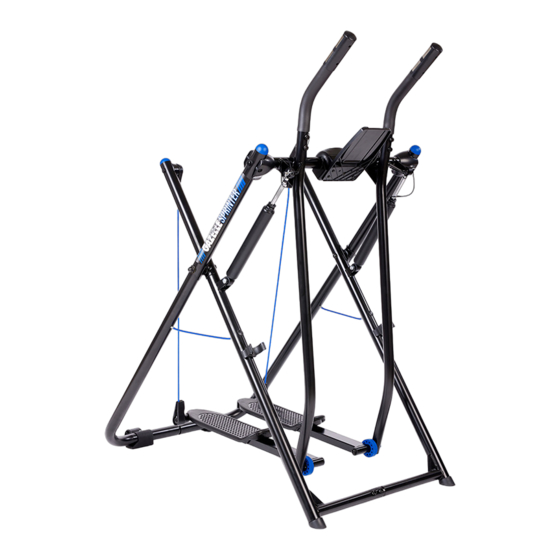
covers
wheels
hydraulic
fitness
storage clips
computer
axle tube
handgrips
left
frame
assembly
left
right
swing arm
swing arm
assembly
assembly
ASSEMBLY INSTRUCTIONS
A. L ay the two frame assemblies & swing arm assemblies on the fl oor
as shown. Make sure the rear frame is on top & that the cables pass
freely above all the frame tubes.
Note: Be careful you do not allow the cables to get behind
the swing arms.
B. Remove all the bolts from the bottom of the frame assembly.
Note: There are two on the rear frame & two on the
underside on the front frame.
C. Slide the left & right wheel holder onto the rear frame as shown,
line up holes & insert the screws (tighten).
D. Slide the right & left bottom frame assemblies together
& hand tighten only the bolts removed in Step B.
device
holder
Tools Required for Assembly:
1 Allen Wrench & Screwdriver (provided)
2 Wrenches (provided)
spare C
washers
right
axle tube bolts
spare bolts
frame
(crossbar bolts)
for handle
assembly
wrenches
fastener pack
TOP OF UNIT
cables
B
BOTTOM
D
C
insert
screws
D
C
wheel
holders
wire
holders
screws
for wheels
allen wrench +
screwdriver
front
frame
B
C
rear frame
(curved)
Advertisement
Table of Contents

Related Manuals for Gazelle SPRINTER


Summary of Contents for Gazelle SPRINTER
- Page 1 (curved) © 2022, 2017 Gazelle Home, LLC. Gazelle® is a registered trademark. All rights reserved. wheel No part of this document may be reproduced or utilized in any form, by any means electronic, mechanical or otherwise without the express written consent of the copyright holder.
- Page 2 & swing arms. (“C” washers can be spread unit. See Owner’s Manual for “Storing Your placed between swing arms & frames). unit out Gazelle” instructions. WARNING: When in use, the cylinders get very hot. DO NOT touch & please keep children away.
- Page 3 INSTALLATION OF FITNESS COMPUTER NOTE: Be sure to follow the instructions below to correctly mount the computer to the Gazelle unit prior to ® operating. INCLUDES: Computer, Magnet Cluster, Batteries & M6 Screw (if installing device holder attachment, the M6 screw will be replaced with the larger loose screw that comes with the device holder attachment).
-
Page 4: Remove Batteries
5. Removal of batteries will reset all values to zero. © 2022, 2017 Gazelle Home, LLC. Gazelle® is a registered trademark. All rights reserved. No part of this document may be reproduced or utilized in any form, by any means electronic, mechanical or otherwise without the express written consent of the copyright holder. - Page 5 M6 screw with the larger loose screw that comes with the device holder attachment. © 2022, 2017 Gazelle Home, LLC. Gazelle is a registered trademark. All rights reserved. ® No part of this document may be reproduced or utilized in any form, by any means electronic, mechanical or otherwise without the express written consent of the copyright holder.
- Page 6 For Maximum Effectiveness & Safety, Please Read This Owner’s Manual Before Using Your Gazelle Sprinter. ® O W N E R ’ S M A N U A L...
- Page 7 Warm-Up & Cool Down Stretches ..........9-10 Target Heart Rate Zone ................11 Getting Started ................... 12 Workout Guidelines ................13-14 Gazelle Sprinter Exercises ............15-17 ® Care, Storage & Resistance ............18-19 Total Fitness Program ................19 Workout Progress Charts ............. 20-21 Exercise Data Chart .................
-
Page 8: Specifications
HAVE PLENTY OF CLEARANCE BEHIND & IN FRONT OF YOUR GAZELLE ® SPRINTER. It is important to keep children, pets, furniture & other objects out of the way of the swinging foot platforms. You should have a minimum of 3 feet... - Page 9 If you are just starting an exercise program, choose a time of day that’s good ® an important step toward achieving your fitness goals. Whether that means for you & then stick closely to it. Try to do your Gazelle Sprinter workout ®...
-
Page 10: Quadriceps Stretch
® training offers the opportunity for greater workout variety, cardiovascular that results from repetitive Sprinter movements. 10 to 12 minutes of daily benefits & increased calorie burning. Interval training means alternating stretching is recommended. This should be done when warming up &... - Page 11 4. Back Stretch BEFORE STARTING THIS OR ANY TARGET HEART RATE ZONE OTHER EXERCISE PROGRAM, Stand with your legs shoulder width apart & your knees Minimum Maximum CONSULT YOUR PHYSICIAN, who (50%) (80%) slightly bent. Bend forward from your waist with your can assist you in determining the target arms extending loosely in front of your body.
-
Page 12: Foot Placement
® carpeted surface with plenty of clearance space behind & in front of the You will notice that your feet shift a little bit when using your Gazelle ® swinging foot platforms. Practice getting on & off your unit a few times Sprinter. - Page 13 On the following pages are eight exercises that will comprise your basic increase the length of your stride as far as Gazelle Sprinter workout. Before performing any of the exercises, first ® you comfortably can. Your heels will naturally read through these instructions for correct exercise execution.
- Page 14 Keeping your WATCH TONY LITTLE’S wrists straight, pull back firmly with alternating GAZELLE® GLIDER WORKOUT VIDEOS arms. Make sure you are leaning back from your ON OUR YOUTUBE CHANNEL! ankles, a full body lean, rather than rounding your back or “sitting”.
- Page 15 Clip both hydraulic safety pin & cylinders into place The Gazelle Sprinter workout will help with the first two parts of your Total ® disconnect before folding. Fitness Program, but you need to make healthy, low-fat eating a big priority both hydraulic cylinders.
- Page 16 Use the chart below & the charts on the following pages to keep track of RESTING TARGET ACTUAL DATE CHEST BICEPS WAIST ABDOMEN HIPS THIGHS CALVES WEIGHT HEART HEART HEART your progress over time. Before writing on them, make as many copies as RATE RATE RATE...
-
Page 17: Workout Time
GAZELLE HOME, LLC | Limited Warranty Update once a week For a period of 12 months from date of receipt, Gazelle Home, LLC warrants that this product will be free from defects in materials & workmanship. This warranty applies only when purchase of the product... - Page 18 STORY TO SHARE? We’d love to hear from you! gazelleglider.com/submit-your-success-story/ © 2022, 2017 Gazelle Home, LLC. Gazelle is a registered trademark. ® All rights reserved. No part of this booklet may be reproduced or utilized in any form, by any means electronic, mechanical or otherwise without the express written consent of the copyright holder.
Need help?
Do you have a question about the SPRINTER and is the answer not in the manual?
Questions and answers