Advertisement
Quick Links
Advertisement

Related Manuals for marutsu TB67H400AHG


Summary of Contents for marutsu TB67H400AHG
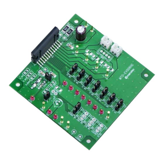
- Page 1 Instruction Manual for Evaluation Board of TB67H400AHG Sep. 2018 Rev.1.0...
-
Page 2: Product Outline
Product Outline The TB67H400AHG is a dual channel DC brushed Motor Driver that supports both the constant current PWM control and the direct PWM control, and is capable to control two DC brushed DC independently. By adopting Bi-CD process, maximum Output withstand voltage of 50V and maximum Output current of 4.0A/channel as absolute maximum ratings are realized. - Page 3 Basic Notes in use of this evaluation board Power Supply Voltage and Operating Range In using the TB67H400AHG, the voltage should be applied to the VM and VREF pins. The absolute maximum rating of VM (Power supply voltage for motor) is 50V, but operating range of the power supply is 10 to 47V.
- Page 4 Explanation of Each Abnormality Detection Circuit TSD (Thermal Shut Down) When the junction temperature (Tj) of this chip exceeds 160°C(typ.),a internal detection circuit stars operation and all outputs are turned off. In the operating state of TSD, IC stays stop mode. After TSD operation, this is canceled by turning the power supply on again or setting to standby mode once by (IN1A, IN2A, IN1B, IN2B, PWMA, PWMB=all Low) and then releasing it.
- Page 5 Connection of Evaluation Board 1 In use of Small Mode Corresponding table of Silk name and Signal name Please note that the names of silk and signal on this board are different each other as follows, because this board is designed and developed as a unfired one for H-Bridge series.
- Page 6 Connection of Evaluation Board 2 A-ch and B-ch are connected In use of Large Mode in parallel to form one H-Bridge, and it drives one motor. Large Mode is a parallel control function of the output part, OUTA+ and OUTA-, OUTB+ and OUTB- are tied ④...
- Page 7 Setting Evaluation Board :1 Setting Motor Current The TB67H400AHG conducts motor operation by PWM constant current control which is based on the frequency of the OSCM oscillation circuit. The maximum current value (set Motor current value) can be determined by a sense resistor (RRS) and the reference voltage (Vref).
- Page 8 Setting Evaluation Board :2 Setting the Chopping Frequency for constant current PWM control In PWM control of the TB67H400AHG, the internal oscillation frequency (fOSCM) and the chopping frequency (fchop) can be adjusted according to the constant of the external components those are connected to the OSCM pin.
- Page 9 VDD pin On this evaluation board, jumpers as shown in the picture above are provided for setting operation of TB67H400AHG When selecting functions by using jumpers, please short the JP_VCC, or supply high level from the VDD pin. The characters surrounded by white square frame close to the jumpers show the Level (H/L).
- Page 10 Setting Evaluation Board :4 Setting for Motor Operation – Input/Output Function INA1, INA2 (Small mode) INB1, INB2 (Small mode) Input Output Input Output PWMA INA1 INA2 OUTA+ OUTA- Mode PWMA INB1 INB2 OUTB+ OUTB- Mode ※Standby ※Standby (High Impedance) (High Impedance) (High Impedance) (High Impedance) STOP (OFF)
- Page 11 Circuit of Evaluation Board Blue bold lines show power lines. 3-position toggle switches or Jumper Socket pin Check pin Jumper Solder land + Through hole Solder land...
Need help?
Do you have a question about the TB67H400AHG and is the answer not in the manual?
Questions and answers