Advertisement
Quick Links
Advertisement

Related Manuals for marutsu TB67S128FTG


Summary of Contents for marutsu TB67S128FTG
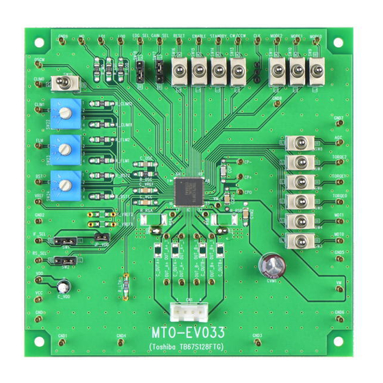
- Page 1 Instruction manual for Evaluation Board - TB67S128FTG - December 20th, 2018 Rev.1.0...
- Page 2 【Outline】 The TB67S128FTG is a two-phase bipolar stepping motor driver using a PWM chopper. CLK-IN control system and BiCD process are adopted. Rating of 50 V and 4.5 A is realized. This evaluation board mounts necessary components to evaluate the IC. Each excitation mode of full step, half step, quarter step 1/8 step, 1/16 step, and 1/32 step is possible with PWM constant current drive.
- Page 3 Connection to evaluation board Power supply (10 V to 47 V) Two-phase bipolar type Stepping motor...
- Page 4 Connection to evaluation board Power supply (10 V to 47 V) Two-phase bipolar type Stepping motor...
- Page 5 Setting evaluation board 1 Setting motor current Setting motor current ①ACDS (RS resistor less) mode: RS_SEL=Low GAIN_SEL=Low: Iout(max) = 1.56 x VREF(V) GAIN_SEL=High: R_VREF2 Iout(max) = 0.78 x VREF(V) R_VREF1 ②External sense RS resistor mode: RS_SEL=High Vref(V) Iout(max) = VREF(gain) x (Ω) GAIN_SEL=Low :VREF(gain) is 1/5.0 (typ.).
- Page 6 Setting evaluation board 2 Setting chopping frequency of the constant current of the motor Formula of setting chopping frequency (-0.8) fOSCM [MHz] = 4.0 x ROSC [kΩ] fchop = fOSCM / 16 COSC = 270 pF (fix) Mounted components are as follows; Capacitor (OSCM=270 pF) COSCM Resistor (ROSCM=5.1 kΩ)
- Page 7 ((3) and (4)) for setting the Setting motor operation operation of the TB67S128FTG and a rotary switch ((2) in the left figure) for adjusting the AGC function are mounted. In using these switches, short-circuit the jumper of JP_VDD (i.e.
- Page 8 Circuit of evaluation board...
- Page 9 Tel:+81-3-6803-0209 FAX:+81-3-6803-0213 Sendai Kamisugi store, Akihabara store, Akihabara store number 2, West Tokyo Office, Shizuoka Yahata store, Hamamatsu Takabayashi store, Nagoya Otai store, Kanazawanishi interchange store, Fukui Ninomiya store, Kyoto Teramachi store, Osaka Nipponbashi store, Hakata Gofukumachi store, marutsu online...
Need help?
Do you have a question about the TB67S128FTG and is the answer not in the manual?
Questions and answers