Liberty Pumps OilTector OTC-115 Manual
Hide thumbs
Also See for OilTector OTC-115:
- Operation and maintenance manual (6 pages) ,
- Operation, maintenance and installation manual (14 pages)
Table of Contents
Advertisement
Operation and Maintenance Manual
Operation and Maintenance Manual
Introduction
Read all instructions thoroughly. Installation of the OilTector must comply with all Federal, State and Local Codes, Regulations
and Practices. The OilTector must be installed by qualified personnel familiar with all applicable local electrical and mechani-
cal codes. Refer to the National Electrical Code (NFPA 70). Failure to properly install and test this product can result in
personal injury or equipment malfunction.
The OilTector control system is designed and approved for the safe operation of pumping, alarming and monitoring of elevator
sump pits, transformer vaults and leachate well applications. The OilTector will activate a pump to remove water from elevator
pits in accordance with ASME A17.1. The OilTector stops the pump before oil or other harmful substances enter our water
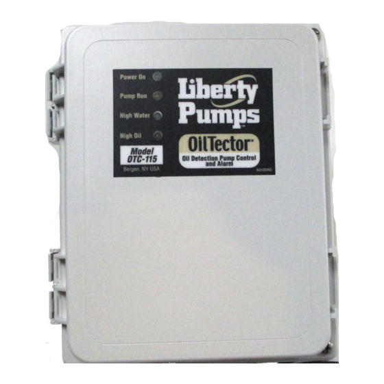
supply. Indicator lights will illuminate on the control panel for the following: power, pump running, high water, high oil. The panel
has a set of auxiliary contacts that activate on power loss or high Oil/Water conditions. These contacts can be connected to the
OilTector remote panel which contains audio/visual alarming along with auxiliary contacts for connection to building automation
system or SCADA system. The recommended minimum sump size is Ø18" x 30" high.
Safety Guidelines
1.
DO NOT USE WITH FLAMMABLE OR EXPLOSIVE FLUIDS SUCH AS GASOLINE, FUEL OIL, KERO-
SENE, ETC. DO NOT USE IN EXPLOSIVE ATMOSPHERES. PROBE/FLOAT SWITCH SHOULD
ONLY BE USED WITH WATER.
2.
DO NOT HANDLE THE OILTECTOR SYSTEM WITH WET HANDS OR WHEN STANDING ON A WET
OR DAMP SURFACE OR IN WATER.
3.
DISCONNECT ALL ELECTRICAL SERVICE BEFORE WORKING OR HANDLING THE OIL ALERT
SYSTEM.
4.
INCOMING VOLTAGE MUST MATCH OILTECTOR SYSTEM VOLTAGE.
5.
TO PREVENT ELECTRICAL SHOCK AND EQUIPMENT MALFUNCTION, USE ONLY WITH A PUMP
SUPPLIED WITH A GROUNDING CONDUCTOR AND GROUNDING-TYPE ATTACHMENT PLUG. BE
CERTAIN TO PLUG THE OILTECTOR PANEL INTO A PROPERLY GROUNDED, GROUNDING-TYPE
RECEPTACLE.
6.
CONTROL PANEL AND ALARM MUST BE MOUNTED INDOORS. FOR OUTDOOR APPLICATIONS
CONSULT FACTORY.
7.
SECURE LEVEL SENSOR ON DISCHARGE PIPE AT A LEVEL THAT GUARANTEES PARTIAL PUMP
SUBMERGANCE WHEN WATER LEVEL IS JUST BELOW THE "OFF" PROBE (THE LONGEST
PROBE). (See Figure 5 on page 3 of this manual). FAILURE TO PROPERLY MOUNT THE LEVEL
SENSOR MAY CAUSE THE PUMP TO ACTIVATE EVEN WHEN OIL IS PRESENT IN THE SUMP.
8.
CAUTION! REMOVE ANY FLOAT SWITCH THAT IS CURRENTLY USED OR SUPPLIED WITH THE
PUMP. IF THE FLOAT CANNOT BE REMOVED, SECURE SWITCH SO THAT IT IS ALWAYS ON.
Part Numbers
OTC-115
- OilTector 115 volt Oil Sensor Control System (Control Panel, Alarm Panel, Level
Sensor). NEMA 1 enclosure.
OTC-230
- OilTector 230 volt Oil Sensor Control System (Control Panel, Alarm Panel, Level
Sensor). NEMA 1 enclosure.
7000 Apple Tree Avenue, Bergen, NY 14416 Phone: (800) 543-2550-Fax: (585) 494-1839-www.libertypumps.com
( 3 1 7 ) 3 4 6 - 4 1 1 0
w w w . d r a i n a g e s o l u t i o n s i n c . c o m
Page 1 of 9
Manual 7235000I
DWG#7235000I
Advertisement
Table of Contents

Subscribe to Our Youtube Channel
Related Manuals for Liberty Pumps OilTector OTC-115


Summary of Contents for Liberty Pumps OilTector OTC-115
- Page 1 Operation and Maintenance Manual Operation and Maintenance Manual Introduction Read all instructions thoroughly. Installation of the OilTector must comply with all Federal, State and Local Codes, Regulations and Practices. The OilTector must be installed by qualified personnel familiar with all applicable local electrical and mechani- cal codes.
-
Page 2: Description Of Operation
Operation and Maintenance Manual Operation and Maintenance Manual Description of Operation On water rise, level reaches pump “start” probe to start the pump. Pump will remain on until level is below “off” probe. The “off” probe senses air or oil and turns the pump off so the oil layer will not be pumped out of the sump. -
Page 3: Circuit Board
Operation and Maintenance Manual Operation and Maintenance Manual Operation and Maintenance Manual Installation of Preset Level Sensor Holder 1. Review figures 4, 5 and 6. 2. Attach sensor holder to discharge pipe or separate pipe (mounted to side wall) using the stainless steel pipe clamp. - Page 4 Operation and Maintenance Manual Operation and Maintenance Manual Operation and Maintenance Manual Introduction Before proceeding with the installation or operation of the Oil Tector Remote Alarm, read all instructions thoroughly, as well as complying with all Federal, State and Local Codes, Regulations and Practices.
- Page 5 Operation and Maintenance Manual Operation and Maintenance Manual Operation and Maintenance Manual Installation of the Oil Tector Remote Alarm Continued 1. To install/replace the battery for the backup power feature, remove the access cover (Fig. 1) and install 9 VDC battery (Fig.
- Page 6 Operation and Maintenance Manual Operation and Maintenance Manual Operation and Maintenance Manual Installation of the ALARM UNIT Continued 3. Continued. If connecting to existing alarm security system or (BAS) system leave terminals + & - open and use 18 gauge 2 conductor wire to connect the existing product to terminals 2A,2B, 1A,1B (Fig. 9). When connected, replace the Caution! access cover and pull the wire through the knockouts on the access cover (See Step #4) .
- Page 7 Operation and Maintenance Manual Operation and Maintenance Manual Operation and Maintenance Manual Installation of the Oil Tector Remote Alarm Continued 6. Connect the Oil Tector Remote Alarm to the auxiliary contacts marked C, O & W in the control panel. C on the alarm to C in the panel. O on the alarm to O in the panel.
- Page 8 Operation and Maintenance Manual Operation and Maintenance Manual Operation and Maintenance Manual Operation and Maintenance Manual Testing the complete system Upon complete installation of controls, pump and piping, test the complete system. 1. Test high oil circuit by lifting the float switch with the sump empty of water. Oil is non conductive like “air”, and when the float is lifted only the HIGH OIL indicator will be illuminated.
-
Page 9: Maintenance
Operation and Maintenance Manual Operation and Maintenance Manual Operation and Maintenance Manual Operation and Maintenance Manual Maintenance 1. The preset level control must be kept clean and free of rust, mud, soap or any conductive material. 2. Every year clean probes keeping them free of debris, calcium or iron deposits. 3.
Need help?
Do you have a question about the OilTector OTC-115 and is the answer not in the manual?
Questions and answers