Table of Contents
Advertisement
Quick Links
Advertisement
Table of Contents

Subscribe to Our Youtube Channel
Related Manuals for Gradall 534B-9


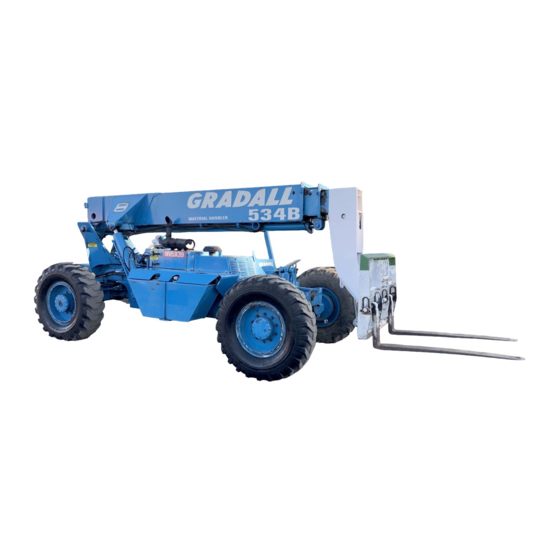
Summary of Contents for Gradall 534B-9
-
Page 2: Important Safety Notice
Safe operation depends on reliable equipment and proper operating procedures. Performing the checks and services described in this manual will help to keep your Gradall Material Handler in reliable condition and use of the recommended operating procedures can help you avoid accidents. - Page 3 Replacement manuals, decals instruction plates can be ordered from your Gradall If you have any questions regarding the material handler, contact your Gradall Material Handler Material Handler Distributor. Distributor. Serial Number Location Operator Qualifications Operators of the material handler must be in good...
- Page 4 NOMENCLATURE...
- Page 5 SAFETY HIGHLIGHTS Read and understand this manual, the Gradall Ma- Operators of this equipment must have successfully terial Handler Safety Manual and all instructional completed a training program in the safe operation decals and plates before starting, operating or per- o f t h i s t y p e o f m a t e r i a l h a n d l i n g e q u i p m e n t .
- Page 6 Decals 9103-3089 Located on Dashboard Part No.9103-3089 Located on Dashboard Part No. 9100-3039 Located on Dashboard Part No. 9100-3040 Located on Boom Lever Knob Located on Right Cab Wall Part No.9103-3279 Part No. 9100-3044...
- Page 7 L I FE, US L OW G EA R WH EN DESCENDING STEEP GRADES. Located on Dashboard Part No. 9103-3443 WHEN TRAVELLING AT HIGH SPEEDS FOR OVER 2 MILES, DISENGAGE 534B-9 9103-3395 REAR HUBS BY REVERSING SMALL Located on Mudguard COVER PLATE AT HUB CENTER. Part No. 9103-3395...
-
Page 8: Hydraulic Oil
Decals (cont.) IMPORTANT HYDRAULIC OIL To prevent damage to the electrical system when using booster battery or charger, always connect 7702-3006 (+) POSITIVE TO POSITIVE Located on Hydraulic Reservoir ( -) NEGATIVE TO NEGATIVE Part No. 7702-3006 Located on Battery Cover Part No. - Page 9 Decals (cont.) PRESSURIZED- COOLING SYSTEM REMOVE CAP DO NOT INSERT HAND IN SLOWL Y OPENING WHILE ENGINE IS RUNNING 9103-3011 9104-3210 Located on Engine Cover Located on Engine Cover Part No. 9103-3011 Part No. 9104-3210 DO NOT USE OXYGEN U S E “ O I L P U M P E D O R D R Y N I T R O G E N . ” NO RIDERS CONSULT DEALER BEFORE CHARGING ACCUMULATOR 9104-3206...
- Page 10 Optional Equipment Decals • AUXILIARY CONTROLS 406 HILL AVE. S.W. NEW PHILADELPHIA. OHIO MADE IN U. S. A. LEVER ATTACHMENT OPERATION SERIAL NUMBER LEFT/DOWN WEIGHT CAPACITY HYD. PRESSURE THE CAPACITY OF FORKLIFT. ATTACHMENT AND FORK COMBINATION MAY BE LESS THAN THE CAPACITY SHOWN ON ATTACHMENT - CONSULT FORKLIFT NAMEPLATE AND ALSO INSURE FORKS ARE OF PROPER SIZE.
-
Page 11: Operator's Cab
OPERATOR’S CAB The standard cab is open on three sides and includes variations operator size. adjustment overhead guard provide protection from release/lock lever is located beneath front edge of falling objects. s e a t . We a r s e a t b e l t a t a l l t i m e s . An optional windshield wiper is available for use with enclose cabs. - Page 12 Horn Button: Depress button to sound horn. Hourmeter: This meter indicates total time of engine A brief description of controls and instru- operation in hours and tenths of hours. ments is provided here as a convenience for the operator. These descriptions DO NOT Ignition Switch: This switch is actuated by a key.
- Page 13 C H E C K S A N D S E R V I C E S B E F O R E S TA R T I N G E N G I N E (To be performed at beginning of each work shift) enter these ports, it can shorten the life of o-rings, seals, packings and bearings.
-
Page 14: Starting Engine
ENGINE OPERATION NOTE: If engine is being started at beginning of work shift be sure to perform all “CHECKS AND SERVICES BEFORE STARTING ENGINE” (page 12). Starting Engine Check to be sure that all controls are in neutral time while cranking engine. Repeat if necessary. If you use a different starting aid, be sure to follow and that all electrical components (lights, heater, manufacturer ’s... -
Page 15: Stopping The Engine
Stopping the Engine Operate engine at idle speed for a few minutes before turning it off. This allows engine coolant and lubricating oil to carry excessive heat away from Allow engine to run at idle for a few minutes critical engine areas. to allow the turbo components to cool. -
Page 16: Brake System
BRAKE SYSTEM General Service Brakes The brake system furnished on the handler includes a The service brake is applied to the front wheels of the service brake and parking brake. handler. Because service braking and “inching” (slow travel) Oil for the brakes comes from the pilot circuit pump, functions overlap, some features of inching will be thru an accumulator charging valve and the accumu- discussed here. -
Page 17: Steering System
STEERING SYSTEM important that operator practice Ninety degree rear wheel power steering is provided maneuvering the handler in a safe, open area until to reduce operator fatigue and to permit high becomes thoroughly familiar with steering m a n e u v e r a b i l i t y i n c l o s e q u a r t e r s . response and clearance required for tailswing and l o a d w h e n t u r n i n g . -
Page 18: Drive Train
DRIVE TRAIN General Transmission The drive train provides two and four wheel drive The transmission provides three speed ranges for includes engine torque converter trans- both forward and reverse travel. mission drive shaft and front and rear driving axles. Inching travel is directly related to drive train functions and will be discussed in this section. - Page 19 Rear Driving Axle The rear driving axle includes planetary hubs which travel functions only in first and second gears. There i s n o h y d r a u l i c f l o w t o d r i v e m o t o r s i n t h i r d g e a r. are powered by hydraulic motors mounted on the inner face of the hubs.
- Page 20 LEVELING THE HANDLER Leveling Handler Frame: Raising the boom (loaded or unloaded) when handler is leaning to the side can The handler is designed to permit tilting main frame cause machine to tip over with little or no eight degrees to left or right to compensate for warning and cause serious injury or death.
-
Page 21: Hydraulic Controls
Rated Capacity Chart The rated capacity chart, located on dashboard, indicates maximum load capacities for handlers equipped with Gradall-furnished carriage/fork combination. These capacities apply to the standard With boom raised above horizontal, forks can be carriage/fork combinations except as stated on the inserted under a load by moving boom control lever capacity chart. - Page 22 Numbers across bottom of sample chart (0' to 24') and numbers parallel to boom (1 to 5) represent boom reach as measured from front of tires to CAPACITY CHART: MODEL 534B-9 extended position. Number decals on boom (1,2,3,4 & 5) relate directly to boom extension.
-
Page 23: Approved Attachments
Refer to serial number plate for list of attachments Non standard carriage/fork combinations (greater or approved for use with your handler. lesser capacity) may be furnished by the Gradall Co. at customer request or may be available for instal- lation because they were furnished for a different Non-Approved Attachment application. -
Page 24: Attachment Installation
Operate a handler equipped with an attachment as a Operation of the handler equipped with carriage/fork partially loaded handler. Pay special attention to combination is covered in the Gradall Material capacity and range limits for the handler/attachment Handler Safety Manual, the FIEI Rough Terrain combination. - Page 25 LIGHT MATERIAL BUCKET FORK POSITIONER PRECAUTIONS PRECAUTIONS • Handler must be level when handling a • Always adjust fork position before en- load more than four feet above ground gaging load. level (refer to page 19). • As with all other attachments, handler must be level before handling a load more Retract boom fully before loading bucket.
- Page 26 Install light material bucket on boom head. mast combination. A separate capacity chart must be used for handlers equipped with mast. Study this chart carefully before attempting to handle a load w i t h m a s t a t t a c h m e n t . Observe all precautions and load capacity limits (listed previously) when handling loads with light material bucket.
- Page 27 SWING FORKS Procedure: PRECAUTIONS Remove carriage/fork combination other attachment from boom head (refer to Attachment R e a d a d d i t i o n a l c a p a c i t y i n f o r m a t i o n Installation - page 23).
- Page 28 SLOPE PILE CARRIAGE QUICK - SWITCH MOUNTED WINCH PRECAUTIONS PRECAUTIONS Maximum winch load capacity is reduced Level handler before tilting carriage to fro m n o rma l car ria g e/fo rk lo ad rat i ng engage load (refer to page 19). (refer to next heading - Capacity).
- Page 29 Controls: Capacity: Maximum lift capacity for the truss boom (with or without winch) is shown on serial number plate (located on right cab wall). However, maximum lift capacity applies only to certain areas within boom extension/elevation pattern of handler/truss boom combination.
- Page 30 Refer to Swing Mast Capacity Chart or contact If truss boom winch is furnished, connect auxiliary your Gradall Material Handler Distributor for hydraulic hoses to winch. complete instructions and restrictions on use. Approach truss or truss bundle with boom above and parallel to load.
- Page 31 Inspect supporting surface at delivery point and Install swing mast on boom head and connect have it leveled if necessary. auxiliary hydraulic hoses to swing mast diversion valve hoses. Also connect electrical cable at boom head. Level handler before raising load. Observe all precautions and load capacity limits (listed previously) when handling load with swing mast.
- Page 32 ***Approved Lubricants: Gradall Wet Brake Housing Fluid 1440-4535 or Mobil #424 ****Fill to Level Using Mixture of: 6 pints (2.8 Liters) Gradall Dif. Lube Additive 1440-4534 or Lubrizol #6178 34 pints (16.1 Liters) GL-5-80-90 TORQUE CHART Check torque using an accurate torque wrench to apply maximum torque value shown.
- Page 33 LUBRICATION & MAINTENANCE DIAGRAM LUBRICANT SYMBOLS ATF - Automatic Transmission Fluid CG - Grease, Extreme Pressure DF - Diesel Fuel EO - Engine Oil GO - Multi Purpose Lubricant HF - Hydraulic Fluid MG - Extreme Pressure Moly Lubricant SL - Special Lube TF - Tractor Fluid SYMBOLS = Fitting...
- Page 34 Lube No. of Lube No. of Item Symbol Points Symbol Points Item Daily (or 10 Hour) Lubrication & Maintenance (Service at whichever interval occurs first) 5Week (or 250 Hour) Lubrication & Maintenance (Cont.) Boom Front Top & Side Slide Bearings (extend boom Air Cleaner Element Condition Indicator (check for fully and lube all wear paths - retract &...
- Page 35 C L E A N c a p . Stop engine and check oil level in reservoir and replenish as required. Contact your Gradall Distributor for information concerning oil analysis. TEST PORT Oil sample containers are available from several...
- Page 36 MOVING HANDLER IN EMERGENCY NOTE: Early 534B-9 units were equipped with The following procedure assumes that han- SOMA front drive axles and recent units are equip- dler cannot be moved under its own power. ped with Rockwell front drive axles. Be sure to follow proper instructions for your unit.
- Page 37 If handler is to be pushed, secure unit to pushing vehicle to prevent handler from rolling on its own with NO BRAKES. Pushing or towing handler with engine stopped, accumulator drained and parking brake released can be dangerous because there are NO BRAKES. Although manual steering is possible with- If handler is to be towed, use a rigid connection to out power assist, STEERING WILL BE...
-
Page 38: Hand Signals
HAND SIGNALS Standard Signals - When handler work conditions require hand signals, they shall be provided or posted conspicuously for the use of both signalman Special Signals - When signals for auxiliary Instructions - When it is desired to give instructions and operator.
Need help?
Do you have a question about the 534B-9 and is the answer not in the manual?
Questions and answers