Table of Contents
Advertisement
Advertisement
Table of Contents
Troubleshooting

Subscribe to Our Youtube Channel
Related Manuals for Caltta PM790


Summary of Contents for Caltta PM790
- Page 1 PM790 Radio MAINTENANCE MANUAL (Level1) V1.0 版权所有 北京中兴高达通信技术有限公司 保留所有权利 第 1 页...
- Page 3 The copyright of this document belongs to Caltta Technologies Co.,Ltd. Text contains proprietary information owned by Caltta Technologies Co.,Ltd., without the written permission of Caltta Technologies Co.,Ltd., any unit or individual shall not use or leak any document and pictures, this document contains tables, picture, data and other information.
-
Page 4: Table Of Contents
5.2 Back of Main PCB........................34 6 Troubleshooting Maintenance Flow....................34 6.1 Structural Part Failure.........................34 6.2 Baseband Circuits Troubleshooting Overview............... 34 6.3 No Power On Current......................... 35 6.4 Power On Failure and Current Over 1A.................. 35 All rights reserved. No spreading abroad without permission of Caltta. - Page 5 6.8.5 Remote Speaker Microphone Failure................41 6.9 No Voice Failure.......................... 41 6.10 No Sound (Speaker) Failure....................42 7 Check After Maintenance........................42 7.1 Check Latest Firmware Version and Device Information.............42 7.2 Function Check..........................42 All rights reserved. No spreading abroad without permission of Caltta.
-
Page 6: Overview
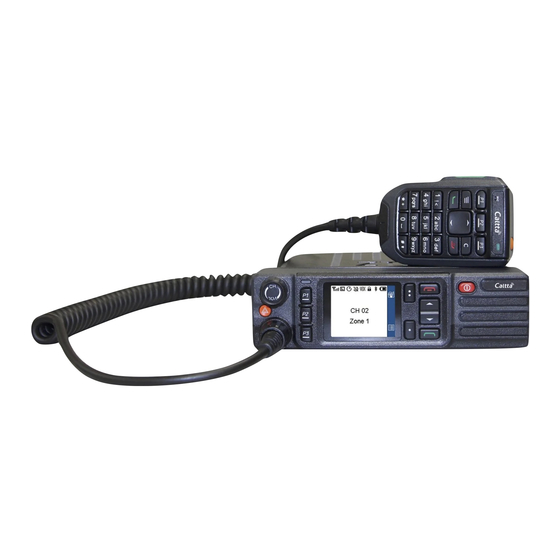
This picture is for reference only, please refer to the actual product. 1.2 Standard Package Item Quantity (PCS) PM790 Radio Unit Keypad Microphone Power Cable Quick Start Guide Screw Fuse Mounting Bracket Bracket Screw GPS/BeiDou/GLONASS Active Antenna All rights reserved. No spreading abroad without permission of Caltta. -
Page 7: Specification
-57 dBm (TIA603D) Emission Transmitter 1-24W/5-44W (UHF3/UHF1); Low Power Output 1-24W/5-49W (VHF) 2-25W/6-45W (UHF1/UHF2/UHF3); High Power Output 2-25W/6-50W (VHF) FM Modulation 12.5KHz: 11K0F3E / 25KHz: 16K0F3E 4FSK Digital 12.5KHz Data Only: 7K60F1D&7K60FXD All rights reserved. No spreading abroad without permission of Caltta. -
Page 8: Function Test
Fix) - Cold Start TTFF (Time To First <10s Fix) - Hot Start Horizontal Accuracy <10m 2 Function Test 2.1 Basic Function Test Component Item Test Method and Requirements Involved All rights reserved. No spreading abroad without permission of Caltta. -
Page 9: Check Firmware Version And Device Information
Check the firmware version, DSP version, RCDB version, frequency range and serial number, etc. Or get the device information by reading through CPS. You can contact after sales to get version comparison table. All rights reserved. No spreading abroad without permission of Caltta. -
Page 10: Software Upgrade
1) Click to open the upgrade software, choose the language according to your requirement (Cn for Chines, En for English); 2) Double click setup.exe in the chosen language folder; 3) Click Next in the below interface; All rights reserved. No spreading abroad without permission of Caltta. - Page 11 PM790 Radio Maintenance Manual 4) Select ‘I accept’ and click Next in the below interface; All rights reserved. No spreading abroad without permission of Caltta.
- Page 12 PM790 Radio Maintenance Manual 5) Select Complete and click Next if you use the default installation path; Select Custom and click Next if you choose your own installation path; All rights reserved. No spreading abroad without permission of Caltta.
- Page 13 PM790 Radio Maintenance Manual Click Change to modify the installation path, then click Next; All rights reserved. No spreading abroad without permission of Caltta.
- Page 14 PM790 Radio Maintenance Manual 6) Click Install to confirm installation. 7) Wait the installation to complete. Click Finish to end one-click upgrade procedure. All rights reserved. No spreading abroad without permission of Caltta.
- Page 15 The LED indicator glows green in upgrade mode: 4) After the upgrade software detects the USB port and displays it, you can select the All rights reserved. No spreading abroad without permission of Caltta.
- Page 16 5) You can choose Chinese or English language, and choose if preserve the current setting data when upgrade the radio. 6) The LED indicator flashes green during the upgrade, the radio displays the following interface: 7) Upgrade complete prompt; All rights reserved. No spreading abroad without permission of Caltta.
-
Page 17: Cps Software
8) Reboot the radio after upgrade to check if the firmware is the target version. 3.3 CPS Software 1. CPS Software Installation Procedure 1) Start installation, double click to install; 2) Click Next following the prompt. All rights reserved. No spreading abroad without permission of Caltta. - Page 18 PM790 Radio Maintenance Manual 3) Select ‘I Accept’ and click Next. All rights reserved. No spreading abroad without permission of Caltta.
- Page 19 PM790 Radio Maintenance Manual 4) Select Complete and click Next if you use the default installation path. Select Custom and click Next if you choose your own installation path. All rights reserved. No spreading abroad without permission of Caltta.
- Page 20 PM790 Radio Maintenance Manual Click Change to modify the installation path, then click Next. All rights reserved. No spreading abroad without permission of Caltta.
- Page 21 PM790 Radio Maintenance Manual 5) Click Install to confirm installation. 6) Wait the installation to complete. Click Finish to end CPS tools installation procedure. All rights reserved. No spreading abroad without permission of Caltta.
- Page 22 Precondition: The radio is power on in user mode. 1) Connect the radio with data cable, and connect data cable USB port to the computer, click CPS read to display the following interface; All rights reserved. No spreading abroad without permission of Caltta.
- Page 23 Precondition: The radio database version and type code are consistent with the database version and type code of the data currently edited by the CPS software. The radio is power on in user All rights reserved. No spreading abroad without permission of Caltta.
- Page 24 2) Connect the radio with data cable, and connect data cable USB port to the computer, click CPS write to display the following interface; 3) Click OK to continue, the radio displays writing and the CPS interface displays as below; All rights reserved. No spreading abroad without permission of Caltta.
- Page 25 PM790 Radio Maintenance Manual 4) The radio automatically reboots after about 10 seconds. The CPS will indicate write success as below. All rights reserved. No spreading abroad without permission of Caltta.
- Page 26 PM790 Radio Maintenance Manual 5) Click OK to complete CPS write. All rights reserved. No spreading abroad without permission of Caltta.
-
Page 27: Radio Disassemble Demonstration
PM790 Radio Maintenance Manual 4 Radio Disassemble Demonstration 4.1 Tools Item Anti-static Glove Anti-static Wrist Strap Tweezers Sockets Screwdriver (Cross Screwdriver, Slotted Screwdriver, T6 Torx Screwdriver) Soldering Iron All rights reserved. No spreading abroad without permission of Caltta. -
Page 28: Disassemble Steps
3. Remove the volume knob, loosen the six fixing screws, take out the speaker and PCB from the control panel. 4. Use the slotted screwdriver to open the buckles on both sides of the radio to remove the back cover. All rights reserved. No spreading abroad without permission of Caltta. - Page 29 PM790 Radio Maintenance Manual 5. Remove the seven fixing screws of the aluminum case top cover, and take away the top cover. All rights reserved. No spreading abroad without permission of Caltta.
-
Page 30: Assemble Steps
6. Remove the fixing nuts of GPS antenna interface and signal antenna interface, remove the two screws of PA module, remove the FPC and take out the main PCB. 4.3 Assemble Steps The assemble steps can refer to the disassemble steps and vice versa. All rights reserved. No spreading abroad without permission of Caltta. -
Page 31: Components
PM790 Back Cover Sealing Gasket PM790 Speaker Air Filter PM790 Aluminum Back Cover PM790 Speaker Sealing GM650 Screw M3*12.5 Gasket PM790 Speaker Holder PM790 Plastic Back Cover PM790 Speaker Sealing GM650 Screw M2.5*6 All rights reserved. No spreading abroad without permission of Caltta. - Page 32 PH790 O Ring PM790 Cooling Silicone 1 GM650 10 Pin Connector PM790 Bracket Sealing Gasket 10 Pin Plug Connector GM680 M3 Screw Sealing Gasket Coding Switch PM790 Ground Steel Sheet All rights reserved. No spreading abroad without permission of Caltta.
-
Page 33: Hardware Pictures
PM790 Radio Maintenance Manual 5 Hardware Pictures 5.1 Front of Main PCB Item GPS Antenna Interface DB26 Interface Power Interface Antenna Interface 50 Pin FPC Interface All rights reserved. No spreading abroad without permission of Caltta. -
Page 34: Back Of Main Pcb
After the radio is powered on, the radio starts normally and the current is about 330mA. During the startup process, the LED indicator flashes green and the LCD displays normally. When the LCD All rights reserved. No spreading abroad without permission of Caltta. -
Page 35: No Power On Current
Measure if the TP26 level of the main PCB keyboard is 0 when the power and FPC button is pressed? Replace the main PCB 6.4 Power On Failure and Current Over 1A All rights reserved. No spreading abroad without permission of Caltta. -
Page 36: Power On Failure And Current Below 1A
Power on is OK but can’t connect USB Can the radio reboot Is the USB cable normally when USB normal? cable connected? Replace the Replace the main PCB USB cable All rights reserved. No spreading abroad without permission of Caltta. -
Page 37: Gps Failure
LCD No Display Re-plug the Is the 50pin FPC FPC and in poor contact? retry Can LCD display Replace the normally after replacing main PCB control header module? Replace the keypad All rights reserved. No spreading abroad without permission of Caltta. -
Page 38: Bluetooth Failure
Bluetooth Failure Re-connect Is the Bluetooth the Bluetooth antenna connected antenna normally? Is the Bluetooth normal after re-burning software? Is the Bluetooth normal after replacing keypad? Replace the main PCB All rights reserved. No spreading abroad without permission of Caltta. -
Page 39: Keypad Failure
Re-assembly the Re-plug the 50pin sheet assembled in good contact? keypad sheet FPC or replace it properly? Replace the keypad Is keypad normal after replacing it? Replace the main PCB All rights reserved. No spreading abroad without permission of Caltta. -
Page 40: No Sound (Speaker) Failure
Is it normal after replacing the speaker? Is the 50 pin Re-plug the FPC FPC normally? or replace it Is it normal after Replace the replacing the front main PCB panel? All rights reserved. No spreading abroad without permission of Caltta. -
Page 41: Remote Speaker Microphone Failure
No Voice Failure Is the voice normal after replacing remote one? speaker microph Check whether Is the current the CPS normal when frequency is pushing PTT? correct Replace the main PCB All rights reserved. No spreading abroad without permission of Caltta. -
Page 42: No Sound (Speaker) Failure
2. Check if the volume/channel knob and channel knob can operate normally. 3. Install the power supply and power on the radio to check that radio can power on normally and LED indicator is normal. All rights reserved. No spreading abroad without permission of Caltta. - Page 43 6. Turn coding knob to adjust radio frequency and set work mode to the same as another normal radio, and make a voice call test to check if the call can be sent, received, and if the voice is normal. 7. Finish checking. All rights reserved. No spreading abroad without permission of Caltta.
Need help?
Do you have a question about the PM790 and is the answer not in the manual?
Questions and answers