
Summary of Contents for Rosendahl nanosyncs HD
- Page 1 Instruction Manual Rosendahl nanosyncs HD Rosendahl nanosyncs HD is a professional video and audio sync reference generator. www.rosendahl-studiotechnik.com - 1 -...
- Page 2 - 2 -...
-
Page 3: Table Of Contents
Contents 1. Unpacking and Mounting into a 19" Rack page 2. Installation page 3. Front Panel page 4. Rear Panel page 5. Video Reference page 10 6. SD/HD Video Generator Settings page 12 7. Audio Reference page 14 8. Sample Rate and Multipliers page 17 9. -
Page 4: Unpacking And Mounting Into A 19"Rack
Please check that all these items are present and contact your dealer if anything is missing. The nanosyncs HD housing is a standard 19" rackmount type, 1U high. Use four rackmount screws to mount the unit into a standard 19"... -
Page 5: Installation
Word clock cables should be under 20 metres to retain maximum benefit from the nanosyncs HD ultra low jitter clocks. The optimum solution is to mount the nanosyncs HD in the same 19“ rack as the most important AD/ DA digital audio converters in your studio. -
Page 6: Front Panel
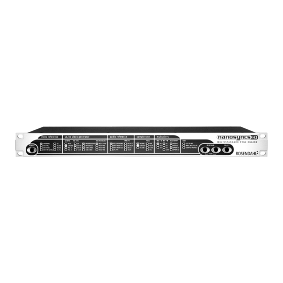
3. Front Panel (S1) Power Switch: Switches the unit from standby power down mode to normal operation mode and vice versa. (L1) (L2) Video Reference: The first four LEDs (L1) indicate the selected video reference. INTERNAL, EXT.PAL, EXT.NTSC or EXT.TRI LEVEL. The second column (L2) displays the detected frame rate. - Page 7 L9 L10 L11 L12 L13 (L9) (L10) Sample Rate: The base sample rate of the audio clock generator can be set to 44.1 or 48kHz. The blue locked LED indicates the audio lock status according to the selected audio reference. (L10) indicates applied word clock pull up or down rates: +4% (25/24), +0.1% (1001/1000), -0.1% (1000/1001) or -4% (24/25).
-
Page 8: Rear Panel
40-200 kHz at 1,5 - 5 Vpp levels. (C9) LTC Time Code Input (RCA): LTC time code (also called SMPTE) is read by the nanosyncs HD and translated into MTC via the USB midi port. The audio clock generator can also be resolved to the LTC applied on this input. - Page 9 MAC or PC host computers (Operating systems Windows-XP or Mac-OSX are required for the midi device class functionality). Supports MTC and MMC as well as Rosendahl Sysex commands for remote and update functions. (C12- C19) Word Clock Outputs (BNC): Word clock outputs WO1-WO6 can be configured to output base sample rates (44.1/ 48 kHz) as well as x2 (88.2/ 96 kHz) or x4 (176.4/...
-
Page 10: Video Reference
5. Video Reference To navigate through the settings you must enter the setup mode by pressing one of the MENU keys [◄] or [►]. The currently selected parameter section starts flashing to indicate you are in the setup mode. With the MENU buttons [◄] and [►] you can move form one section to the next. - Page 11 A 30 fps "black & white" input signal is indicated by the 30 fps LED without -0.1% LED. The nanosyncs HD will also lock to 30 fps signals. EXT.TRI LEVEL: The unit locks to an external Tri Level Sync signal applied on the video sync input connector (C7).
-
Page 12: Sd/Hd Video Generator Settings
6. SD / HD Video Generator Settings The nanosyncs HD generates one SD video sync standard and one HD tri level standard simultaneously. You can set the frame rates and formats independent for the SD and HD generator section. Both standards are always frequency locked to the selected video reference, also when the frame rates are different. - Page 13 VO1-VO3, VO4, VO5 and VO6 can be individually set to output the SD or HD generator signal. In addition VO6 can be configured to output black Rosendahl bi-level syncs for Dolby Encoder/ Decoders. See page 25 nanoSETUP software for more details.
-
Page 14: Audio Reference
FOLLOW VIDEO: The audio clock generator follows to the selected video reference. If you want to use the nanosyncs HD as a studio master set the video reference to INTERNAL and the audio reference to FOLLOW VIDEO. To synchronise the audio clocks to an external video reference you must slave the video section to this external video reference and set the audio reference to follow video. - Page 15 1:1 (AES and SPDIF outputs are limited to Fs x2 rates up to 100 kHz). You can use nanosyncs HD as a word clock distributor which follows to all incoming sample rates automatically with the advantage that all clocks are regenerated. This results in highest clock quality on all outputs independent of the word clock input signal used.
- Page 16 WORD 1:1 it is not possible to access the sample rate and multiplier sections in the menu. LTC FPS: The nanosyncs HD is also able to resolve audio word clock signals to external, free running LTC time code signals. Only forward running timecode within a +/- 10% window, is used as a reference.
-
Page 17: Sample Rate And Multipliers
8. Sample Rate and Multipliers Enter the setup mode and select the sample rate section (L9). (See page 12 for more informations how to navigate through the different setup sections.) The base sample rate of the audio clock generator can be set to 44.1 or 48kHz. -
Page 18: Ltc Time Code Generator
9. LTC time code generator From firmware 2.0 you can also start the internal LTC time code generator manually without connecting to a host computer. Therefor a new menu section has been implemented, indicated by blinking LED "MMC/ MTC to LTC". The new menu section appears next to "SPDIF"... -
Page 19: Usb Midi Port, Mtc And Mmc
The nanosyncs HD unit is detected as Standard Audio Device (OSX shows also the device name as nanosyncs HD). Any application which uses MIDI ports can use the nanosyncs HD as midi in or out port. LTC to MTC: Connect a LTC time code signal to the time code input (C9). - Page 20 To synchronise a DAW to MTC time code open the nanosyncs HD midi port in your DAW application software and make the according settings. Please see also the instructions of your DAW software for synchronisation to MTC. The LTC to MTC translation is an independent process in the nanosyncs HD and works within all operation modes.
- Page 21 Most DAW software applications are able to send MMC commands. The nanosyncs HD accepts MMC commands via the USB to control the integrated LTC time code generator (LTC output on C10). In firmware 2.0 the following MMC commands are implemented:...
-
Page 22: Configuration Protection
MTC to LTC: Midi Time Code (MTC) can be generated by most DAW software. When the nanosyncs HD is receiving MTC from DAW software it will trigger start the internal LTC time code generator accordingly. This means a new detected MTC signal sets the LTC generator to the corresponding position and starts the generator. -
Page 23: Firmware Update
Visit www.nanosyncs.com and download the newest nanosyncs HD firmware file (NFXXXX.DAT) and the nanoSETUP software for Windows XP. Make a USB connection from your computer to the nanosyncs HD using the supplied USB A-B cable. Now start the software "nanoSETUP". The serial number and firmware version of the connected nanosyncs HD unit(s) are displayed. -
Page 24: Nanosetup Software
A premature termination of the software update process leads to the complete loss of the firmware but does not erase the nanosyncs HD BIOS. Please switch the unit off and on again, use the Read command and restart the firmware update procedure again. - Page 25 VIDEO REFERENCE = EXT. PAL and SD STD = PAL VIDEO REFERENCE = EXT. NTSC and SD STD = NTSC. In these two operation modes the nanosyncs HD synchronises by default the colour subcarrier 1:1 to the incoming subcarrier (colour burst).
- Page 26 (s. page 23). "NTSC" LED in column L3 indicates activated NTSC PEDESTALS. "PAL" LED in column L3 indicates USE INTERNAL SUBCARRIER. "VO6=HD" LED in column L6 indicates BLACK ROSENDAHL VO6" "x256" LED in column L12 indicates PILOTTONE ON WO8". Options -> Varispeed Use varispeed to generate non standard sample rates locked to the video reference.
- Page 27 Options -> LTC time code generator nanoSETUP utility software allows to control the LTC generator for using the nanosyncs HD as an LTC master generator. 23,98, 24, 25, 29.97, 29.97d and 30 FPS standards can be selected without respect to the SD/ HD generator standards.
-
Page 28: Declaration Of Conformity
14 . Declaration of Conformity Rosendahl Studiotechnik GmbH Andechser Str. 5 D-86919 Utting a.A. Germany herewith confirms that the product: Type: professional video and audio sync reference generator Model: nanosyncs hd meets the requirements of the council of the European communities relating to electromagnetic... -
Page 29: Specifications
15 . Specifications USB: USB 2.0, class compliant midi device, plug and play under windows XP or Mac OSX MTC, MMC and Rosendahl SYSEX for firmware updates video input: BNC, 75 ohms terminated, accepts SD bi-level syncs and HD tri-level syncs... - Page 30 - 30 -...
- Page 31 - 31 -...
- Page 32 - 32 -...
Need help?
Do you have a question about the nanosyncs HD and is the answer not in the manual?
Questions and answers