
Subscribe to Our Youtube Channel
Related Manuals for Kverneland Exacta-CL-GEOSPREAD

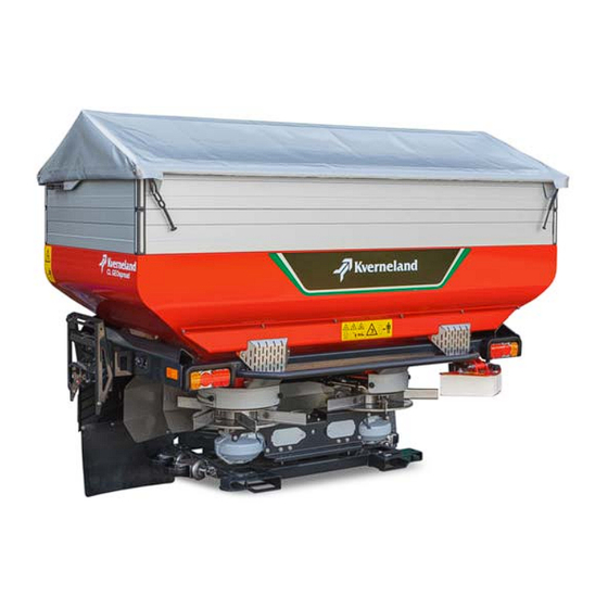
Summary of Contents for Kverneland Exacta-CL-GEOSPREAD
- Page 1 Exacta-CL-GEOSPREAD User Manual Item 02-2018 Print date 02.2018 Language From software version V 1,16 From machine number 1001 Serial number From VN263 Reference number A138454040-2...
- Page 2 Hoofdweg 1278 NL-2153 LR Nieuw-Vennep The Netherlands Kverneland Group Nieuw-Vennep B.V holds all copyrights and rights of use. The contents of this user manual can be modified without prior noti- fication. All rights reserved. The right to technical revision is reserved.
-
Page 3: Table Of Contents
Table of contents Table of contents Preface ............Use in the field ........... 144 Target group of this manual Adjusting the machine Meaning of symbols Spreading on field Start spreading Safety ............Border spreading For your safety Stopping work Other guidelines Failure and stoppage Warning stickers Safety requirements... -
Page 4: Preface
Preface Target group of this This manual is intended for agrarians and others trained in working in Preface the field of agriculture, people that are competent to operate these ma- manual chine, as required by national legislation, and who have knowledge of assembly activities. -
Page 5: Meaning Of Symbols
Preface Meaning of symbols Various symbols are used to provide a clear understanding of the text.. These are explained below • A dot is placed before lists. A triangle marks tasks you have to perform. An arrow refers to a different place in the text. In addition, we use pictograms to help you to easily find certain text sections. -
Page 6: For Your Safety
Safety For your safety In this chapter you will find general safety instructions. In every next Safety chapter you will find more specific safety instructions not described here. Do not risk injury or death by ignoring good safety instructions. Many risks can happen when working with agricultural machines. Avoid accidents! Do not take risks! Be alert! Think safety! Work in safety! Disregard of the 'Safety instructions', inadequate maintenance, use of... -
Page 7: Warning Stickers
Safety Warning stickers Various warning stickers have been affixed to the machine for safety reasons. Do not remove them! Always follow the instructions supplied and be alert to possible dangers. Always keep the safety stickers and symbols clean and clearly legible. Replace safety decals that are missing, damaged or have become il- legible. - Page 8 Safety Explanation for warning stickers Stop the engine and remove the keys from the ignition Switch the engine off as soon as you leave the tractor. Remove the key from the ignition to prevent the tractor from being started uninten- tionally while you are in the danger zone.
- Page 9 Safety Only lift the machine at the lifting points If a machine is being elevated, only attach it to the indicated lifting points. Never go underneath an elevated machine. Allow for any pos- sible movements of the elevated machine, whether wanted or not. Be careful of getting jammed or pinched If the machine is engaged or operated unintentionally you could get struck in moving parts, which could lead to injury.
-
Page 10: Safety Requirements
Safety Safety requirements This part contains all the requirements, everything that is not permitted and requirements for each form of usage, maintenance and reparation of the machine. The chapters in the manual contain additional safety measures. Knowledge of the safety regulations forms the basis for safety and proper usage of the machine. - Page 11 Safety Authorisation Only to be used by an authorised person The machine may be used by authorised people only. A person is au- thorised if he/she: • received training as required by the national authorities, • has taken responsibility as described in ...
- Page 12 Safety Workplace To be used and operated by 1 person The machine may only be operated by one person, from the tractor. Operating the machine from the tractor will keep you out of harm's way. Other people should not be in the direct vicinity of the machine and the tractor.
- Page 13 Safety Put a fire extinguisher in place Carry a fire extinguisher at all times, especially when operating in dry crop materials. This should be a multi-purpose ABC rated extinguisher with a 5 kg capacity, approved by the appropriate authority. Mount this on the tractor and/or on the machine.
- Page 14 Safety Required details The following details are necessary in order to calculate the minimum requirements and actual axle load, as well as the actual and maximum total weight. The details of the tractor should be given in the tractor manual. The details of the tyres should be supplied by the manufac- turer.
- Page 15 Safety Calculations The calculations can be made with the values given in the above chart. Actual total weight The actual total weight must not exceed the permitted total weight. The actual total weight (in kg) is calculated as follows: Actual total weight (kg) = A + D + E Actual front axle load The actual front axle load must not exceed the permitted maximum load.
- Page 16 Safety Ballast required in the rear The minimum load on the rear axle must be 45% of the basic weight of the tractor. With a machine mounted in the front power lift the mini- mum required ballast (in kg) in the power lift behind the tractor is cal- culated as follows: ( D x f ) - ( C x g ) + (0.45 x A x g ) Rear ballast required (kg) =...
- Page 17 Safety Machine Check the condition of the machine before use Check the following before using the machine: • is the machine in a proper, functioning condition? • are all lights, safety and warning provisions correctly mounted and in good working condition? •...
- Page 18 Safety Coupling shaft Use the correct coupling shaft Only use coupling shafts complying with the manufacturer’s specifica- tion for that specific use! In order to ensure protection of both man and machine exercise extreme caution when working at a coupling shaft other then described in this manual and/or on the instruction at the coupling shaft.
- Page 19 Safety Electronic control system Disconnect the control box Disconnect the control box from the electric system as soon as no more functions are needed in order to prevent unintentional operation. Keeping the control box connect can be dangerous and can damage the machine as well as cause bodily injury.
- Page 20 Safety Transport Check the decoupling ropes of the quick coupling The decoupling ropes must never be tense and must provide sufficient freedom for movement, even with the power lift in the lowest position as it could otherwise accidentally disconnect the quick coupling. Drive carefully Moving behaviour, manoeuvrability and braking performance are influ- enced by a trailed machine.
- Page 21 Safety Maintenance Always keep to the prescribed maintenance intervals Take the machine for inspection and maintenance at the intervals as prescribed in this manual. All of the manufacturer's responsibility and the guarantee will become null and void if the prescribed intervals are not adhered to.
- Page 22 Safety Avoid contact with materials You should only come into contact with the materials when cleaning the machine. Always wear protective clothing, such as safety gloves, shoes and goggles. Read and adhere to the additional safety instruc- tions and the of the material producer. Contact with the materials could lead to injury.
-
Page 23: Getting Familiar With The Machine
Getting familiar with the machine Applications of the ma- This PTO shaft driven machine is suited for spreading granular ferti- Getting familiar with the machine liser on the field and grazing land. chine It is attached • to the three-point power lift of the tractor (Cat. II), or Border spreading is possible by using the following: •... -
Page 24: Adjust Carefully
Getting familiar with the machine Adjust carefully The spreader has two actuators per dosing unit to set the application rate and working width independently of each other. Moreover, it is possible to shut 2 of the 3 dosing openings so that the application rate can also be set precisely with a low flowrate, while the risk of block- ages remains limited. - Page 25 Getting familiar with the machine Width distribution with The spreading pattern is determined by the transverse distribu- GEOSPREAD tion. The discharge point is the place where the fertiliser granules come into touch with the vanes of the spreading disc and substantially de- termines width distribution.
- Page 26 Getting familiar with the machine Display of the sections in the The active sections are displayed in black triangles in the main screen main screen for both sides: • The working width of 24 metres is divided into 2 x 6 sections of 2 metres and controlled by the GEOCONTROL.
-
Page 27: Spreading Pattern
Getting familiar with the machine Spreading pattern Optimum distribution of the fertiliser with minimum impact on the envi- ronment can be achieved through the settings and tools described. Full field spreading pattern The full field spreading pattern overlaps 100% A triangular spreading pattern that completely overlaps can be ex- pected with most fertiliser types with an average working width. - Page 28 Getting familiar with the machine One-sided boundary You can drive along the field edge with a half spreading pattern filled spreading with border to 100% with the border spreading plate and one closed dosing unit. You have to optimise the spreading pattern and thereby overcome en- spreading plate vironmental pollution when adjusting the border spreading plate.
- Page 29 Getting familiar with the machine Boundary track spreading It is possible to spread right up to the border (boundary track spread- with ExactLine ing) from the first sprayer tramline with ExactLine. Selecting the pattern for border spreading It is not possible to completely cover the field border at the application rate and not have anything go beyond the border.
- Page 30 Getting familiar with the machine Gored spreading with The headland in this example is first sprayed anti-clockwise with the GEOCONTROL ExactLine to the right (1). The final pass (3) will be included by the headland (1) and the previous complete pass (2). The GEOCONTROL software will reduce both the working width and application rate first to the left (4-6), and thereafter to the right (7).
-
Page 31: The Iso Control System
Getting familiar with the machine The ISO control The ISO control system uses the ISOBUS communication protocol, which makes it suitable for tractors that are also equipped with an ISO- system BUS communication system. For tractors that still do not have an ISO- BUS connection, your dealer can supply the universal IsoMatch terminal to which you can connect all ISOBUS machines. - Page 32 Getting familiar with the machine The computer calculates the required fertiliser flowrate with the follow- ing formula: Working width (m) x Driving speed (km/h) x Application rate (kg/ha) Flowrate required = (kg/min) Automatic Calibration test With the data from the spreading chart book and the automatic cali- bration tests that the spreader carries out every 75 kg or every minute, the computer determines what dosing setting corresponds with what flowrate.
- Page 33 Getting familiar with the machine The ISO tractor ISOBUS tractor connection The switching functions and data transfer between the tractor terminal or ISO control box and the machine are operated via the ISOBUS. Specifically tilling the site and reacting to deviating field forms or soil compositions is possible through ISOBUS communication.
- Page 34 Getting familiar with the machine The control box The working method and work performance of the IsoMatch control box are described in this user's manual. IsoMatch universal ISOBUS terminal Many functions and programmes on one control box The divided colour screen has a flexible division to: •...
- Page 35 Getting familiar with the machine • Extra functions: • Calculator • Internet browser • Camera screen (Camera is optional) • Status bar for time, GPS signal strength and driving direction • Save and read: • Documents • Tractor data • Field particulars •...
- Page 36 Getting familiar with the machine IsoMatch Tellus Compact and complete IsoMatch Go, as a handy and more compact variant of the double- screen version, offers complete ISO control with all functions. Besides the smaller dimension with the single screen, the number of USB con- nections and the absence of Wlan/Wifi constitutes the biggest differ- ence.
- Page 37 Getting familiar with the machine Configuration screen With the configuration screen key, you directly reach the screen where you can modify the various settings of your IsoMatch. Consult the user's manual of the control box or tractor for further information.
- Page 38 Getting familiar with the machine Manuals screen Manuals tab The manuals screen can be opened with this tab. Manuals screen The operation manual of the IsoMatch and all other applications are given here. • You can go up and down through the list with the arrows •...
- Page 39 Getting familiar with the machine Keyboard (pop-up) Let us suppose that you want to change the working width: Touch the working width value in the main screen. The keyboard comes up in the main screen. IsoMatch keyboard Main screen with GEOSPREAD keyboard Value to be modified Current working width: 24m...
- Page 40 Getting familiar with the machine pull down menu Before choosing a given application or letter value, a menu of the value to be changed with various choices below one another may ap- pear after the touch. We call it a pull down menu in this manual. ...
- Page 41 Getting familiar with the machine Main menu In the main menu you will find all the information related to the spread- ing process or the machine while spreading. Moreover, you can use the function keys to carry out the most important functions immedi- ately, such as over and underdosing or closing a spreading disc.
- Page 42 Getting familiar with the machine Menu structure...
- Page 43 Getting familiar with the machine...
- Page 44 Getting familiar with the machine GEOCONTROL Menu The GEOSPREADER with specific site control via GEOCONTROL has its own application screen. If you have the spreader control as an application in the uppermost screen, the GEOCONTROL application can be selected in the lowest screen.
-
Page 45: Technical Specifications
Getting familiar with the machine Technical specifica- tions Exacta-CL GEO 1100 1100 1550 2000 2450 General Content of the hopper (l) 1100 1550 2000 2450 Filling level (cm) Filling width (cm) Hopper's width (cm) Weight*(kg) Maximum load capacity (kg) 2800 2800 2800 2800... -
Page 46: Technical Specifications
Getting familiar with the machine Technical specifica- tions Exacta-CL GEO 1300 1300 1800 2300 2800 General Content of the hopper (l) 1300 1800 2300 2800 Filling level (cm) Filling width (cm) Hopper's width (cm) Weight*(kg) Maximum load capacity (kg) 2800 2800 2800 2800... -
Page 47: Technical Specifications
Getting familiar with the machine Technical specifica- tions Sound level Closed cabin Rear window opened Tractor at 540 rpm (dB) 70.4 75.7 Tractor + operating, empty spreader (dB) 71.4 81.0 Tractor + spreading spreader (Kali 60) (dB) 72.7 84.2 Tractor + spreader (Kali 60) + ExactLine (dB) 70.9 85.5 Miscellaneous... -
Page 48: Before First Use
Before first use Inspection of the sup- The machine would generally be assembled and delivered ready-for- Before first use use by the dealer. The dealer is also responsible for providing instruc- plied machine tions for use and maintenance. He/she must also ensure that the re- quired documents are provided, such as: •... - Page 49 Before first use Be careful that nothing gets jammed It is easy for parts to get jammed while mounting the spreader. Work carefully: • place the machine on adequate supports, • switching off the PTO shaft, • releasing the pressure from the hydraulic system, •...
- Page 50 Before first use Console assembly Mount the control box in a place where it would: • be well visible, • easy to operate while spreading, • and result in minimal visual hindrance while driving the tractor. The console has two range and height adjustments to provide optimal view of the control box.
- Page 51 Before first use IsoMatch terminal on an ISO If you use the IsoMatch control box with a tractor manufactured with tractor the ISOBUS communication system, you can connect it with the sup- plied CAN cable to a standard tractor CAN connection. IsoMatch terminal on a NON- If you use the IsoMatch control box with a tractor that is not equipped ISO tractor...
- Page 52 Before first use Hopper extensions A hopper extension increases the load capacity of the spreading hop- per. All edges consist of: A long side • 2 long sides, • 2 short sides, • 4 corner parts, • 4 caps, • fixing material.
- Page 53 Before first use Hopper cover The hopper cover must be mounted on top of the hopper or hopper ex- tension to protect the content against weather or spray. Also see the spare parts manual for the correct assembly. Place the hinges on the coaming or hopper extension. The hinge Hinge with the handle must be placed on the left side.
- Page 54 Before first use Parking wheels Only park with an empty hopper Only park the machine on the parking wheels if the hopper is empty! Parking with a filled hopper results in reduced stability. Moreover, the wheels are not designed for heavy loads. Damages to the machine and physical injury can be caused.
- Page 55 Before first use Vanes Three vane combinations, as illustrated in the diagram, must be used for different working widths. Working width (m) Vane combination 10-18 135-185-235 20-24 185-235-285 24-28* 285-235-285 * Optional Vane position on the disc ") ") ") Optional 24-28 (78-92 ft)
- Page 56 Before first use ExactLine The ExactLine is used for border spreading from the sprayer tramline. Also see the spare parts manual for the correct assembly. Use a spirit level to position the machine horizontally on the ground Container Hinge or on proper supports.
- Page 57 Before first use Check the operation of the position sensor in working position: Set the plate right across the sensor. Start the tractor and engage the control box. Check whether you have set the position of the ExactLine as illustrated, see ...
- Page 58 Before first use Hydraulic border The hydraulic border spreading plate is used to spread the sides while spreading plate moving alongside the field edge. Fit the border spreading plate to the machine, see also the parts Suspension points Sensor sheet.
- Page 59 Before first use Position indicator A sensor is available with these accessories to be able to read in the tractor cabin whether the ExactLine and/or the hydraulic border spreading plate are in the working position. A splitter box will be supplied if more than one of these accessories are fitted.
- Page 60 Before first use Calibration container The calibration container is used to control the dosing setting of the machine. The calibration container must be mounted on the left spreading disc driving rod for the calibration test. Remove the vanes. Turn the nuts on the bolts on which the gearbox is mounted to the turning rod back 5 mm.
-
Page 61: Tractor Provisions
Before first use Tractor provisions Working with the machine requires a tractor that at least meets the fol- lowing requirements: • sufficient carrying and lifting capacity and engine power, see paragraph »Technical specifications« on page 45, • correct type of properly adjustable power lift, •... -
Page 62: Mounting The Coupling Shaft
Before first use Mounting the The coupling shaft provided is too long for most types of tractors The coupling shaft must be cut to the correct length before connecting coupling shaft it to the tractor. A coupling shaft that is too long could lead to serious damage to the machine and the tractor. - Page 63 Before first use Shortening the coupling The profiled tubes must overlap as far as possible, with a minimum of shaft 150 mm. The profiled tubes must however have at least 25 mm free clearance at the outer edges when the tractor PTO shaft and the machine drive axle are level.
-
Page 64: System Settings
System settings System settings For a correct control system operation, it is necessary to set and cali- bre the spreader before first use or after an alteration to the machine, for example after fitting extra accessories. Moreover, you can enter a number of system settings to increase your ease of use. -
Page 65: Entering System Settings
System settings Entering system The system settings are needed for the good operation of the control system. Moreover, this enables you to enter your user preferences, for settings example, for alarm signals. Link the machine up as described in ... - Page 66 System settings ExactLine position If the spreader is equipped with a hydraulic border spreading plate and/or ExactLine, the position, working position or transport mode can be displayed on the main screen. The position is poorly visible from the tractor. By means of the display on the main screen, you should make fewer spreading errors caused by incorrect hydraulic border spreading plate and/or ExactLine positioning.
- Page 67 System settings Select the side of the field boundary for recording the field edge. This can be (R) or (L) in case of the hydraulic border spreading plate. Start spreading. The field edge will now be recorded with the given width in the screen 'Curve Calibration'.
- Page 68 System settings Driving speed signal The remaining system settings are in the ‘Settings’ screen. Press the scroll key to go from the ‘Curve Calibration’ to the ‘Settings’ screen. You must enter the source of the driving speed signal on the top line. Deviation By means of the signal, the spreader adapts the dosing setting so that reference sensor...
- Page 69 System settings Deviation of the reference During calibration of the reference sensor, the outgoing signal is set at sensor '0'. As a result of changing circumstances, for example temperature differences, or in the event of wear and tear, the reference sensor can produce a deviating signal after some time.
- Page 70 System settings Supply voltage alarm For good control system functioning, the voltage on the feeder cable must be at least 10.5 volts. Switching on the alarm causes a warning to appear on the screen if the supply voltage is lower than a value that you have preset.
- Page 71 System settings Over and underdosing unit During spreading, you can manually (one-sided) over- or under dose on the main screen. By pressing 1 time on the plus key or minus key beside the screen, you can adjust the application rate by a percentage Over and underdosing unit of the application rate or a preset number of kilograms.
-
Page 72: Settings Behind Pin Code
Auto-calibration limit on/off and limit value of automatic calibration • Selection of weighing system, Exacta-CL EW 1 weighing sensor or Exacta-TL(X)/Exacta-CL-GEOSPREAD 4 weighing sensors. The option for 3 weight sensors is a service function. • Auto-calibration setting for large, medium-sized or small field •... - Page 73 System settings Automatic calibration limit Auto-calibration with external control of the application rate In some cases, it is advisable to switch the automatic calibration off flowrate (kg/min) temporarily. For example, if you are spreading by means of an external signal. It can also happen that the dosing unit is closed at any time while the spreader is connected.
- Page 74 System settings Selection for the weighing Depending on the type of spreader, Exacta-CL EW or Exacta-TL(X)/ system Exacta-CL GEOSPREAD is selected in the field below for: 4 weighing sensors with Exacta-TL(X)/Exacta-CL GEOSPREAD 1 weighing sensor with Exacta-CL EW. Selection of Exacta-CL-GEO- SPREAD weighing system ...
- Page 75 System settings Gored spreading is not/is Spreading subsequently in case of field boundaries which are possible not right-angled Sometimes you cannot spread across the full working width during passes. A spreader with the option of adjusting the working width automatically via a GPS can perform gored spreading.
- Page 76 System settings Sensor selection Depending on the type of accessory you select: none Hydraulic border spreading plate (Center) ExactLine Right Multiple accessories through splitter box(Sensor box). See »Position indicator« on page 59, Sensors selection Sensors selection Weighing system While spreading on very hilly terrain, the weight in the main screen filter...
- Page 77 System settings Settings screen (4) Make your choice here: • select border spreading plate, manual or hydraulic • select actual or calculated value Border spreading This screen allows you to check whether the border spreading plate is plate manually or hydraulically operated. Manual Hydraulic border spread-...
- Page 78 System settings Setting ISOBUS The spreader can be driven by an external signal, which could for in- communication stance be transmitted by a GPS receiver, nitrogen sensor or memory card. To assign a controlling function to the external signal, it must be received in the 'Task Controller' screen.
- Page 79 System settings Using the Spreader control First 25 hours of use free software If the spreader is capable of • being driven by an external acceptance rate • or is equipped as a 'GEOSPREAD' machine Counter for time of use of free software this can be used for 25 hours free of cost.
- Page 80 System settings Setting machine data The position of the signal receiver and the place where the machine works effectively are mostly different. Distance of spreading disc Your spreader will, depending on the fertiliser characteristics: to work pattern on the • shape and roughness of the granules, ground •...
- Page 81 System settings The control system can now calculate the correct speed reduction for subsequent spreading on the headland and during gored spreading. Move the choice in the input field Task controller and external ap- plication rate. 0° See paragraph »Setting communication with an external system« on page 78.
-
Page 82: Spreader Calibration
System settings Spreader calibration It is very important that the weighcells and actuators be calibrated cor- rectly for the spreader to function properly. Your spreader is supplied calibrated. The actuators need only be recalibrated if one or both of them are replaced. Incorrect calibration will result in a deviating application rate and con- sequent damage to the crop. - Page 83 System settings Hopper weight calibration The weighcells weigh the hopper's mass, including accessories fitted to the hopper and the hopper content. The control system must know the weight of the hopper content in order to, for example, to calculate how many more hectares you can spread before the hopper is empty. Or to sound the hopper alarm at the right time.
- Page 84 System settings Press the OK key to confirm the PIN code cancel with the Cancel key. Press the arrow key to go to the second screen of the hopper calibration. If you attach something to the hopper yourself, you must increase the NDICATION hopper weight with the weight that appears on the main screen when the hopper is empty.
-
Page 85: Alarms
System settings Alarms If the control system cannot perform the requested function, a warning will appear on the screen. The system has 3 different types of alarm: • User's alarms; this appear when the spreading function cannot be performed adequately or at all. •... - Page 86 System settings System alarms If a system alarm appears on the control box screen, you must stop immediately. The spreader cannot perform the requested function ad- equately because the power supply is insufficient or the actuators are not responding correctly. Fix the failure before working any further. The supply voltage of the control system has gone below the set alarm level.
-
Page 87: Service Information
System settings Service information The control system can provide all kinds of information on the machine as well as store it in some cases. This information will be used by the dealer when checking the machine or by service engineers in case of problems and failures. - Page 88 System settings Diagnosis menu You will find the lens key in every settings and service menu screen. By pressing this key, you will reach the diagnosis menu. In the diag- nosis menu, you will find information on the control system, software, current measurement data, etc.
- Page 89 System settings Logbook The screen indicating important events is displayed by pressing the logbook key on the screen in which the software version is displayed. The control system registers when and how often important events took place. An alarm is also displayed in most instances. The history can be very useful in solving failures.
-
Page 90: Connecting To The Tractor
Connecting to the tractor Connecting to the tractor Neutralise the controls Control devices, e.g. ropes, hoses, etc. for remote actuation of de- vices such as cylinders, shall be guided and positioned in a way they never inadvertently release nor block desired movements/actuations! Unintentional movements can lead to serious injury. -
Page 91: Selecting Linkage Pin Height
Connecting to the tractor Selecting linkage pin There is an option of two tension levels, depending on the height of the crop. The high hitch points are for normal use, the low hitch points height are used if the maximum lifting height of the tractor is not sufficient to ensure that the spreading height is 75 cm above the crop. - Page 92 Connecting to the tractor Coupling the coupling shaft The coupling shaft provided is too long for most types of tractors The coupling shaft must be cut to the correct length before connecting it to the tractor. A coupling shaft that is too long could lead to serious damage to the machine and the tractor.
- Page 93 Connecting to the tractor Connecting hydraulic hoses In case your machine is equipped with the ExactLine/Hydraulic border spreading plate (accessory), you must connect the hydraulic hose for operation. Valves Check the hydraulic quick coupling on the tractor for dirt. Clean if necessary.
- Page 94 Connecting to the tractor Connecting the power lift Check the decoupling ropes of the quick coupling The decoupling ropes must never be tense and must provide suffi- cient freedom for movement, even with the power lift in the lowest po- sition as it could otherwise accidentally disconnect the quick coupling.
-
Page 95: To Be Done Before Spreading
To be done before spreading Find the correct Avoid contact with the fertiliser and other material To be done before spreading You will most likely get into contact with the fertiliser and other material settings for the you may wish to spread while filling, adjusting and testing the spreader and set it spreader. - Page 96 To be done before spreading Determine the type of fertiliser based on the shape and surface: TYPE Operation pattern Surface Granular rough roughly round, sometimes slightly rough angular, no sharp corners or edg- smooth roughly round, not angular, no relatively smooth sharp corners or edges mineral angular, with sharp angles and...
- Page 97 To be done before spreading Determining distribution The distribution is the ratio of granules with different diameters. A dis- tribution meter comes with every spreader. This meter has 4 sections, with sieves. The sieves have different mesh width that divide the ferti- liser granules, based on their diameters.
- Page 98 To be done before spreading Determining specific weight The specific weight is the weight (kg) of 1 litre of fertiliser and it is ex- pressed as kg/litre or ton/m3. The following material is required to determine the specific weight: • a measuring cup of minimum 1 litre with a correct scale division, •...
- Page 99 See paragraph »Check the spreading pattern (tray test)« on page 127. You can reach the spreading chart service as follows: Go to the website of the Kverneland Group: http://www.Kvernelandspreadingcharts.com. The various languages are given at the top of the page.
-
Page 100: Setting The Spreader
To be done before spreading Setting the Avoid contact with the fertiliser and other material You will most likely get into contact with the fertiliser and other material spreader you may wish to spread while filling, adjusting and testing the spreader. - Page 101 To be done before spreading Enter the selected application rate or connect the reception of the external signal, see paragraph »Constant application rate« on page 107, paragraph »Variable, externally driven application rate« on page 122. Set the correct rpm for the PTO shaft, ...
- Page 102 To be done before spreading The spreading chart from the example looks as follows: 18 m 1,05 kg/ltr Universal 16 (NPK 16-16-16) Yara kg/ha kg/min kg/min 6 km/h 8 km/h 9 km/h 10 km/h 11 km/h 12 km/h 14 km/h - 30 - Granula 18+0...
-
Page 103: Working Width
To be done before spreading Working width The working width must be selected to set the spreader. This could for instance be the distance between the sprayer tramlines. In the spreading chart book, via the online spreading chart service on the website or via the free application (App) for mobile phones with an iOs and/or Android operating system, look for the page that shows the desired working width of the fertiliser type with the most similar prop-... - Page 104 To be done before spreading The following will be achieved with the fertiliser and spreading chart from the example: See paragraph »Example« on page 101. The advised vane combination with an application rate of 365 kg/ha with a working width of 18 metres and a driving speed of 8 km/h: 135 / 185 / 235.
- Page 105 To be done before spreading Discharge point It is necessary to correctly set the discharge point in order to obtain a good spreading pattern and the correct working width. The point at which the granules or seeds come onto the spreading disc can be changed by setting the discharge point.
-
Page 106: Inclination
To be done before spreading Inclination In the spreading chart, look for the Angle spreader symbol to get ad- vice on the angle of your spreader. The spreader is normally in the horizontal position. It may be necessary to adjust the spreader's angle with large working widths or with top dressing. -
Page 107: Application Rate
To be done before spreading Application rate The control system can drive the spreader in three different ways: • distribution that resembles the settings for the preset application rate must be determined under changing circumstances through automatic calibration and driving speed correction, ... - Page 108 To be done before spreading Switch the control box on. Press on the input field for the working width. Discharge point letter value The popup keyboard appears on the screen. Working width Selected Input the desired working width. application rate ...
- Page 109 To be done before spreading GEOPOINT The GEOPOINT (Centre spreading pattern) is the distance between the signal receiver and the centre of the spreading pattern. To allow the machine to operate correctly or stop in the right place, you must run the following settings: ...
- Page 110 To be done before spreading Adjust or switch off Working on smaller parcels automatic calibration With low application rates and small parcel size, the time interval be- tween automatic calibration needs to be reduced. See »Adapting auto-calibration to field size« on page 74 and Working with very low application rate If very low application rates are to be distributed, e.g.
- Page 111 To be done before spreading Fine application All three dosing openings normally open uniformly with the selected application rate and the corresponding flowrate that you set. With a Dosing openings low application rate and/or a low driving speed the dosing openings are only opened a slight bit so that very little fertiliser would stream through the dosing openings of the spreader.
- Page 112 To be done before spreading The flowrate through the dosing opening should open three times as much to maintain the same application rate. A flowrate 3 times the se- lected flowrate for the dosing setting must be entered in the ‘Curve Calibration’...
- Page 113 To be done before spreading From the main screen: Press the key switch on the main screen; you will go to the 'Curve Calibration' screen. The 'Curve Calibration' screen Dosing setting flowrate Press on the input field for the dosing setting The popup keyboard appears on the screen.
- Page 114 To be done before spreading 18 m 1,05 kg/ltr Universal 16 (NPK 16-16-16) Yara kg/ha kg/min kg/min 6 km/h 8 km/h 9 km/h 10 km/h 11 km/h 12 km/h 14 km/h - 30 - Granula 18+0 18+3 24+0 24+3 30+0 30+3 36+0 36+3...
- Page 115 To be done before spreading Manually set application If you rate • spread less than 25 kg/ha, • types to be spread with the hopper hardy filled (e.g. slug pellets or seeds), • spreading on very uneven fields (e.g. frozen soil), the control system cannot perform an automatic calibration test.
- Page 116 To be done before spreading Dosing setting The dosing setting to be set can be: • Read from the relevant spreading chart when you want to spread at a lower application rate using the fine application kit and the symbol of the Fine application kit is indicated in the spreading 0°...
- Page 117 To be done before spreading Suppose you would want to spread slug pellets with the characteris- tics given in the spreading chart below: With a working width of 18 metres, a driving speed of 8 km/h and a se- lected application rate of 11,4 kg/ha.
- Page 118 To be done before spreading Suppose you would want to spread NPK 16-16-16 from the example with the features as given in the spreading chart on this page: With a working width of 18 metres, a driving speed of 8 km/h and a se- lected application rate of 22,5 kg/ha.
-
Page 119: Manual Calibration Test
To be done before spreading Manual calibration PTO shaft rotates after disengaging After switching off the PTO shaft, danger could arise as the machine test will continue running because of inertia. Keep a safe distance to the machine until the moving parts have come to a complete stop. Ap- proaching the machine while it is rotating can cause serious or deadly injuries. - Page 120 To be done before spreading The calibration test can now start. Start the tractor again. Switch the control box on. Switching off the automatic calibration Switch the automatic calibration off by pressing the manual/auto key in the main screen. A hand will begin to flash in the screen on the right below the spreader.
- Page 121 To be done before spreading This value is converted to flowrate per minute in kg per minute and adopted in the control system. The dosing setting is now displayed in the ‘Curve Calibration’ screen and the correspond- ing flowrate is indicated in the relevant input field. The given value for the flowrate is approximated, but the control system makes use of the accurate preset value of the manual calibra- tion test.
-
Page 122: Variable, Externally Driven Application Rate
To be done before spreading Variable, externally The control system provides the options to distribute the same appli- cation rate all over the site and the option to spread a variable, exter- driven application rate nally driven application rate. This provides the option to spread as per requirements, e.g. - Page 123 To be done before spreading Setting the control system A few settings in the control system must be checked and adjusted to enable communication with an external system. See paragraph »Setting ISOBUS communication« on page 78. A few settings must also be entered in the driver (software) of the con- trol box or tractor terminal.
-
Page 124: Filling
To be done before spreading Filling Avoid contact with the fertiliser and other material You could come into contact with materials when filling the machine. Always wear protective clothing, such as safety gloves, shoes and goggles. Read and adhere to the additional safety instructions and the of the material producer. - Page 125 To be done before spreading Most types of fertiliser attract water and can thereby form large NDICATION chunks. These chunks can block the spreader or distort the spreading pattern. • When working under moist conditions, use a hopper cover that closes well.
- Page 126 To be done before spreading Work carefully while filling and take the regulations that apply to work- NDICATION ing conditions into consideration! Make sure no objects or tools fall into the hopper as it could block or damage the spreader! ...
-
Page 127: Check The Spreading Pattern (Tray Test)
To be done before spreading Check the spreading Avoid contact with the fertiliser and other material You will most likely get into contact with the fertiliser and other material pattern (tray test) you may wish to spread while filling, adjusting and testing the spreader. - Page 128 To be done before spreading When to perform the tray test: • When using a fertiliser type that is not in the spreading chart book, via the online spreading chart service on the website or via the free application (App) for mobile phones with an iOs and/or Android op- erating system.
- Page 129 To be done before spreading Test the left and right The left and right spreading discs must spread the same volumes of spreading patterns fertiliser to ensure good distribution. Check this every year! This test describes a working width of 18 metres. You are of course NDICATION free to run the test for a different working width.
- Page 130 To be done before spreading Start the tractor again. Working width Selected Close all the doors and windows in the cabin. application rate Switch the control box on. Press the desired application rate in the input field. ...
- Page 131 To be done before spreading Assessment Record the values you find in the graduated tubes for the left and right spreading discs. Compare the values, calculate the percentage differences between the measuring tubes on the left and the right. Adaptation If the spreading patterns on the left and right spreading discs are not the same and the difference is greater than 3% you will have to do the...
- Page 132 To be done before spreading Full field spreading pattern If the spreader is correctly set and the tramlines are set at the correct test distance from each other you would achieve a good distribution of fer- tiliser over the land. This will only be achieved if the spreader spreads with the correct spreading pattern.
- Page 133 To be done before spreading Start the tractor again. Working width Selected Close all the doors and windows in the cabin. application rate Switch the control box on. Press on the input field for the required application rate. ...
- Page 134 To be done before spreading Review and adaptation The content of the separate tubes can differ 15% at most from the av- erage. If the correction seems to be 2 characters too strong after repeating NDICATION the test, set the discharge point back by one character. Good spreading pattern, the spreader has been adjusted well.
- Page 135 To be done before spreading Testing the spreading Always perform a calibration test first and determine the correct dos- pattern of the hydraulic ing setting before checking the spreading pattern. Changes to the dos- ing setting will also have an influence on the spreading pattern! border spreading plate ...
- Page 136 To be done before spreading Set the hydraulic border spreading plate based on the chart below. Increase the dosing with respect to full field spreading by 4 positions. Place 1 trough on the land next to the fictive border ditch and 2 troughs next to each other in the fictive ditch.
- Page 137 To be done before spreading Review and adaptation Ditch side The maximum acceptable loss in the ditch is determined by environ- ment standards (EN 13739-2). In order to comply with the standards the quantity of fertiliser in the 1st trough, standing in the imaginative ditch, must be a maximum of 10% of the quantity collected in the trough in the middle of the track (= 100%).
- Page 138 To be done before spreading Testing the full field Reducing the PTO shaft rpm and closing the right spreading disc also spreading pattern with the have an influence on the spreading pattern on the left side of the spreader. The full field spreading pattern should therefore be tested hydraulic border spreading when using the border spreading plate.
- Page 139 To be done before spreading Testing ExactLine When using the ExactLine the aim is to obtain maximum distribution spreading pattern to the border with minimum loss in the ditch. This is why the ExactLine has to be tested. Do not perform this test next to the ditch, rather mark a line behind which the fictive ditch will Operation ...
- Page 140 To be done before spreading Place 1 trough on the land next to the fictive border ditch and 1 trough next to each other in the fictive ditch. : Position the troughs horizontally with a spirit level! NDICATION Place 1 trough in the middle of the tractor tracks. The driving track must be half a working width from the fictive ditch.
- Page 141 To be done before spreading Review and adaptation Ditch side The maximum acceptable loss in the ditch is determined by environ- ment standards (EN 13739-2). In order to comply with the standards the quantity of fertiliser in the 1st trough, standing in the imaginative ditch, must be a maximum of 10% of the quantity collected in the trough in the middle of the track (= 100%).
-
Page 142: Driving On The Road
Driving on the road Before taking Observe the permissible and safe height with regard to Driving on the road • the road prescribed maximum height for vehicles in the road traffic regula- tions, • high-voltage cables or other cables over the road; •... -
Page 143: Preparing The Machine To Be Transported
Driving on the road Preparing the machine Before travelling on a public road with your tractor and machine, you should do the following: to be transported Check whether tractor and machine are roadworthy. check that the lights, warning indicators, protectors and brakes are attached properly and are working. -
Page 144: Use In The Field
Use in the field Use in the field Friction between moving parts: Be careful of moving parts making contact with each other while work- ing. You could accidentally touch control levers and cause the ma- chine to move. Only start working once all machine parts have stopped and the con- trol lever have been secured. -
Page 145: Adjusting The Machine
Use in the field Most types of fertiliser attract water and can thereby form large NDICATION chunks. These chunks can block the spreader or distort the spreading pattern. • When working under moist weather conditions, use a hopper cover that closes well. •... - Page 146 Use in the field Setting the control system Check the settings of the control system before starting to spread. In the main screen: • Working width, • Discharge point letter value, • Selected application rate, • Step increments with over and underdosing, •...
- Page 147 Use in the field Field registration in the A field registration is provided in the GEOCONTROL application. GEOCONTROL application The task data made and saved in GEOCONTROL can be transferred to a USB stick. See the GEOCONTROL manual saved in your control box as soon as the application is loaded.
- Page 148 Use in the field Last setting check To ensure good spreading results, follow this last check as indicated below. Are you working with the correct settings from the correct spreading chart, based on: • distribution, • specific weight, • type of fertiliser, •...
-
Page 149: Spreading On Field
Use in the field Spreading on field Working with the GEOCONTROL Starting a new task is done from a saved field or one to be created newly with the GEOCONTROL application. Refer to the GEOCONTROL manual in your terminal for this purpose. - Page 150 Use in the field Setting out tramlines If the tractor is equipped with driving a speedometer, the control sys- electronically tem can assist you to set out the tramlines. If you have entered the required working width, the control system can indicate when you must place a further marker.
- Page 151 Use in the field Tramline patterns Your preferred border spreading method determines the tramline pat- tern. Select on the basis of the site width, the presence of the sprayer tram- lines and the spreader's equipment. Using the ExactLine with Drive half the working width from the field edge (1/2 X meters) when tramlines doing boundary track spreading with ExactLine (optional extra).
- Page 152 Use in the field Using the hydraulic border During one-sided boundary spreading with hydraulic border spreading spreading plate with tram- plate, you drive along the outermost work area on the field edge and lines control the fertiliser granule stream by means of the hydraulic border spreading plate (accessory).
-
Page 153: Start Spreading
Use in the field Start spreading To begin spreading, proceed as follows: Close all the doors and windows in the cabin. Drive the tractor to the first tramline, depending on the driving pattern required, which may be recognised by the marker in place. ... - Page 154 Use in the field approaching headland with the GEOCONTROL function switched off: Close the dosing units by pressing the stop key before turning to the headland. The PTO shaft can keep running if you intend to start spreading immediately again. You will find the correct working method and corresponding distances on the headland in ...
- Page 155 Use in the field Working method on the The driving pattern that you use, in other words how you must turn on headland the headland, depends on your border spreading method. • spreading the border from the sprayer tramline with ExactLine and the hydraulic border spreading plate for one-sided boundary spreading with additional room (situation A), or •...
- Page 156 Use in the field Hydraulic border spreading plate Set the field boundary as close as possible to the left while driving along the field boundary, to spread right down to the border with the border spreading plate. Fill the headland through to half the working width without the border spreading plate with the correct dosage selected to make an additional pass.
- Page 157 Use in the field GEOCONTROL headland function Begin with creating the field boundary where you spread down to the border along the field boundary while driving to the left with the border spreading plate and the correct dosage switched off. ...
- Page 158 Use in the field Over and underdosing Depending on soil or crop composition, it is preferable to spread more or less fertiliser locally. With the control system, you can over- or under dose to the left, right or on both sides during spreading. You will find all the control keys on the main screen.
- Page 159 Use in the field If you are over- or underdosing on one side, switch the control system NDICATION over to manual mode. Consequently, automatic calibration will be halted. For this reason, we advise not to start over- or underdosing im- mediately at the beginning of spreading.
-
Page 160: Border Spreading
Use in the field Border spreading Spreading fertiliser up to the border of the property requires concen- tration. On the one hand you want to achieve maximum cover to the field edge to ensure a good crop, while on the other hand you want to minimise the loss over the field edge. - Page 161 Use in the field Working method Switch the tractor off and remove the keys from the ignition. Engage the parking brake of the tractor. Disconnect the right or left spreading disc by sliding the connector (depending on the border to be spread). Secure the connector with a lock clip.
- Page 162 Use in the field Driving pattern Two different driving patterns can be used, depending on the situation on your land. Working from the sprayer tramlines (situation A): Drive the first path with the middle of the tractor about 2 metres from the field edge.
- Page 163 Use in the field Boundary track spreading with ExactLine Operation Drive half the working width from the field edge (1/2 X meters) (=first sprayer tramline) when doing boundary track spreading with the Ex- actLine (accessory). The flow of fertiliser granules, seeds or other granules spread with ExactLine.
- Page 164 Use in the field Working method Engage the ExactLine by letting the relevant single-acting hydraulic valve run for a few seconds. This is also how pressure is built in the accumulator. You will see the ExactLine symbol on the main screen.
-
Page 165: Stopping Work
Use in the field Driving pattern When using the ExactLine, drive in the first sprayer tramline or half the working width (1/2 X meter) from the field edge. 1/2 X m (ft) Stopping work Right after working with the machine, before you leave, you must do the following: ... -
Page 166: Failure And Stoppage
Use in the field Failure and Be careful that nothing gets jammed It is also easy to get injured while working with the spreader. stoppage Work safely with the machine: • releasing the pressure from the hydraulic system, • switching off the electronic control system, •... - Page 167 Use in the field These failures are probably caused by one of the following: • a hard object blocks the agitator, • a hard object or a large piece of fertiliser is (partially) blocking the supply from flowing to the agitator, •...
- Page 168 Use in the field Examine the spreading discs and the discharge opening to see what the cause of the failure/stoppage is. Adapt the discharge point as needed for easier access. If you still cannot see the cause, carefully remove the vanes to see better into the discharge opening of the discharge bushing.
- Page 169 Use in the field stoppage If you have not found any damage, the failure is probably due to stop- page from an encrusted layer of fertiliser. Try to reduce the size of the lump or encrusted layer with an object such as a stick, screwdriver or vane.
-
Page 170: Storing The Machine
Storing the machine Storing the machine Avoid contact with the fertiliser and other material It is easy to come into contact with the materials when putting away the machine. Always wear protective clothing, such as safety gloves, shoes and goggles. Read and adhere to the additional safety instruc- tions and the of the material producer. -
Page 171: Cleaning
Storing the machine Cleaning It is advisable to first lubricate, clean and again lubricate the machine before storing it for a short or longer period of time. If it is lubricated first you will prevent dirt, fertiliser and water from entering the bear- ings. -
Page 172: Disconnecting The Machine
Storing the machine Disconnecting the Disconnect safely You may only disconnect the machine when machine • all parts are in a safe condition, • your immediate surroundings are safe, • the hopper is empty. Work carefully: • check the environment (children!) and ensure that nobody is in the vicinity of the tractor or the machine, •... - Page 173 Storing the machine If you cannot lower the power lift far enough to release the catch hooks, we advise you to place the spreader on a firm, stable ramp, for example a pawl. Drive the tractor about 200 mm forward (maximum distance depends on the range of the coupling shaft;...
- Page 174 Storing the machine Preparation for winter At the end of the season the machine must be prepared for winter stor- storage age. It is advisable to first lubricate, clean and again lubricate the machine before storing it for a short or longer period of time. If it is lubricated first you will prevent dirt, fertiliser and water from entering the bear- ings.
-
Page 175: Maintenance
Maintenance Maintenance Repair damage safely and without delay Repair the machine safely before you continue with work: • place the tractor and machine on a firm, straight surface, • switching off the PTO shaft, • releasing the pressure from the hydraulic system, •... - Page 176 Maintenance Do not modify the machine Do not modify the machine in any way. Unauthorised modifications may impair the function and/or safety and affect the life of the ma- chine. Only use original parts when replacing Using other non-genuine parts could lead to problems and unsafe sit- uations when using the machine.
-
Page 177: Oil And Grease Content
Maintenance Oil and grease Never use more oil or grease than prescribed A too high oil level may result in an overheated machine and damaged content seals. Waste storage and disposal Waste from performing maintenance on the machine could be con- taminated with fertiliser, oil and grease. -
Page 178: Maintenance Intervals
Maintenance Maintenance intervals Keep to the checking and maintenance intervals given below to keep the machine in good working order. Inspection • • »Checking bolts and nuts« • • »Checking the hydraulic system« • Condition of the agitator and the agitator axle •... -
Page 179: Lubricating Points
Maintenance Lubricating points All lubricating nipples of the machine can be filled with a universal grease type. See »Oil and grease content« on page 177. See »Maintenance intervals« on page 178. Coupling shaft with quick The coupling shaft is provided with grease nipples. lock ... -
Page 180: Applying Or Adding Grease
Maintenance Applying or adding grease Coupling shaft profiled tubes You must grease the profiled tubes of the coupling shaft regularly. Ap- ply grease to the contact surfaces of both of the profiled tubes should you note during coupling or decoupling that the halves of the coupling shaft are not sliding in and out smoothly. -
Page 181: Add Oil
Maintenance Add oil The following parts only function well if they are provided with suffi- cient oil. Check this regularly. Connectors The connectors between the central gearbox and the spreading disc gearboxes are used with border spreading, with a calibration test and when checking the spreading pattern with the tray test. - Page 182 Maintenance Torques Guidelines for torques (in Nm) for self-locking nuts, hexagon bolts and nuts. Torques Quality 10.9 12.9 Friction* 0,10 0,13 0,10 0,13 0,10 0,13 0,10 0,13 Thread 1020 1000 1180 * The friction coefficient of 0.10 applies to oiled sheets, cast iron, hard- ened surfaces, greased threads, etc.
-
Page 183: Checking The Hydraulic System
Maintenance Checking the Hydraulic oil is under high pressure Never try to stop a leak with your fingers. Never try to locate a hydrau- hydraulic system lic leak or try to contain it by hand! When inspecting always use appro- priate aid (e.g. - Page 184 Maintenance Inspection criteria It is not permitted to carry out repairs on hydraulic hoses! Replace hoses if the following is detected during inspection: • damage to the exterior up to the armouring (such as abrasion marks, cuts and tears), • the exterior becoming brittle (tears in the hose), •...
-
Page 185: Checking And Setting The Dosing Mechanism
Maintenance Checking and setting Avoid contact with the fertiliser and other material You will most likely get into contact with the fertiliser and other material the dosing you may wish to spread while filling, adjusting and testing the mechanism spreader. Wear protective clothing and safety gloves, read the safety instructions provided by the supplier and follow their directions. - Page 186 Maintenance Set the position of the dosing The dosing mechanism must be mounted exactly in the middle above mechanism the spreading discs. The agitator axle must turn freely from the seal ring. agitator If you open the filters, you should block them to prevent unwanted NDICATION closing.
- Page 187 Maintenance Setting the dosing plates It is necessary to set the dosing plates to the correct positions to each other to ensure correct dosing. If the dosing openings do not close well Cracks you will loose unnecessary fertiliser and the application rate will be higher than intended with a specific dosing setting.
-
Page 188: Checking And Setting The Discharge Point Setting Mechanism
Maintenance Checking and setting Avoid contact with the fertiliser and other material You will most likely get into contact with the fertiliser and other material the discharge point you may wish to spread while filling, adjusting and testing the setting mechanism spreader. - Page 189 Maintenance Attach the rope as per the illustration. Measure the distance between the inside of the rope and the opening of the discharge bushing carefully. If the measured distance is more or less than 109 mm, do the follow- ing: ...
-
Page 190: Checking And Setting The Discharge Bushing Height
Maintenance Checking and Avoid contact with the fertiliser and other material You will most likely get into contact with the fertiliser and other material setting the you may wish to spread while filling, adjusting and testing the discharge bushing spreader. Wear protective clothing and safety gloves, read the safety instructions provided by the supplier and follow their directions. - Page 191 Maintenance Turn the lock nuts on the 4 fastening bolts with which the dosing Lock nut mechanism is attached to the hopper a few times to loosen them. Turn the nuts on the 4 fastening bolts so that the dosing mechanism moves upward.
-
Page 192: Replacing Agitator Axle Seal
Maintenance Replacing agitator Avoid contact with the fertiliser and other material You will most likely get into contact with the fertiliser and other material axle seal you may wish to spread while filling, adjusting and testing the spreader. Wear protective clothing and safety gloves, read the safety instructions provided by the supplier and follow their directions. - Page 193 Maintenance Open the sieves with the included attachment and deposit it. agitator Remove the agitator from the agitator axle. Support the fertiliser bearing ring through a dosing opening so that it will not drop. Remove the 3 fastening bolts from the seal rings. ...
-
Page 194: Accessories
Accessories General Accessories The following accessories for your machine are available to adapt it to your tractor and/or are working conditions. All of the responsibilities of the manufacturer lapse and the guarantee becomes null and void if non-genuine parts are used. IsoMatch control box For complete ISO control, the IsoMatch control box offers many extra new functions. - Page 195 Accessories IsoMatch Tellus GO Compact and complete control box IsoMatch Go, as a handy and more compact variant of the double- screen version, offers complete ISO control with all functions. Besides the smaller dimension with the single screen, the number of USB con- nections and the absence of Wlan/Wifi constitutes the biggest differ- ence.
- Page 196 Accessories Cable with 7-point plugs for ISO Directly to the ISO 11786 in cab tractor connection in the tractor 11786 in cab connection cabin You can mount an optional extension cable to the ISO 11786 in cab tractor connection on the plug of the "Input IM Tellus" cable supplied as a standard item.
- Page 197 Accessories Starguide III / IV With the Starguide III / IV you have the following functions: • DGPS driven steering while spraying and for other treatments, where close monitoring of the progress is required. • Headland management of your spray sections for treatment with a minimum overlap and untreated surfaces.
- Page 198 Accessories IsoMatch Global GPS The latest development in ISOBUS communication is an extension to antenna the IsoMatch terminal for tractors which cannot give any own loca- tional information. The GPS antenna with DGPS accuracy allows sat- ellite navigation for field-specific section control, variable dosing and field registration.
- Page 199 Accessories ExactLine ExactLine is an accurate border spreading tool for boundary track spreading from the last sprayer tramline. ExactLine provides a very good border spreading pattern with an optimal balance between profit and the environment. See paragraph »Boundary track spreading with ExactLine« on page 163.
- Page 200 Accessories Hopper extensions The loading volume of the spreader can be increased by putting one, two or three hopper extensions in place. See paragraph »Technical specifications« on page 45. Hopper extensions Keep the increase in the filling height and the weight of the machine into account.
- Page 201 Accessories Mud guards A set of mud guards is available to protect the machine from being dirt- ied by the tractor wheels. Reflector Motor vehicles with limited speed (<40 km/h), agricultural and forestry tractors and their trailers, as well as other vehicles, must be provided with a red reflector at the rear in the form of a truncated triangle.
-
Page 202: Troubleshooting Table
Troubleshooting Troubleshooting Troubleshooting table Problem Possible cause Solution Incorrect appli- Dosing setting incorrectly set Check the dosing setting cation rates (kg Incorrect setting for fine dosage Set the dosing setting for fine application per hectare) as per the instructions Driving speed signal not correctly set Set the correct source of the driving speed signal in the control system, as well as the control box... - Page 203 Troubleshooting Problem Possible cause Solution Great amounts Average quality fertiliser (too soft, broken, Contact your supplier. of dust while mixed types) or incorrect storage Update the storage area. spreading Spread with smaller working widths as far as possible agitator grinds. Dosing units closed for too Switch the PTO shaft off after closing the long with the PTO shaft running dosing units.
- Page 204 Troubleshooting Problem Possible cause Solution Machine Discharge bushing makes contact with Please contact your dealer makes a noise the spreading disc while running Spreader put down with filled hopper Repair the machine. 185, Set dosing mechanism and discharge point again Spreading disc hidden/ out of balance Check the spreading discs for damage and for the presence of all the vanes...
-
Page 205: Falling Into Disuse
Falling into disuse Falling into disuse When the lifespan of the machine has finished, its separate parts must be properly disposed of. Keep local legislation in mind with this! Metal parts You must deliver all metal parts to a metal recycling company. Plastic parts All plastic parts can be disposed of as unwanted garbage. -
Page 206: Liability
Liability Liability Without prejudice to the other stipulations of these General Conditions Liability and the stipulations of the act on product responsibility, the seller is only responsible for damage caused by culpable breach of contract and by unlawful actions in the framework of the regulations below: 1. -
Page 207: Complaints
Liability Complaints The following stipulations apply, along with national legislation: • The buyer must check the equipment, accessories and spare parts upon delivery for transport damage and completeness. Any possi- ble shortcomings must be reported without delay. • The seller will only consider complaints if the buyer reports that in writing within fourteen days after delivery by the seller. -
Page 208: Ec Declaration Of Conformity
EC declaration of conformity EC declaration of conformity In accordance with EU Direc- tive 2006/42/EC Kverneland Group Nieuw-Vennep BV Hoofdweg 1278 NL-2153 LR Nieuw-Vennep The Netherlands declare fully under own responsibility that the product Exacta-CL-GEOSPREAD weighing spreader in all variants... -
Page 209: Notes
Notes Notes... - Page 210 Index Index fine application inspection Accessories manually set application rate cable with plugs for ISO 11786 in cab Variable, externally driven connection Applications of the machine Calibration container Apply safety drain kit Attachment for sieve opening ExactLine Auto-calibration GEOCONTROL software Adjust or disable hopper cover external signal...
-
Page 211: Index
Index bolts and nuts Diagnosis menu calibration test Diagonal inclination Delivered machine adjusting Discharge point Differences in operation dosing mechanism Discharge bushing field adjustment lubricating points hydraulic system Setting the height spreading pattern Discharge bushing height Cleaning adjustment Clothes/protection inspection Combined control with GEOSPREAD system Discharge bushing height adjustment Complaints... - Page 212 Index External signal Software Setting the control system spreading on field External system TC FnI (control number) adjusting GEOPOINT communication Gored spreading External system communication GEOCONTROL main screen display Grease applying/adding Failure central gearbox causes profiled tubes working method spreading disc gearboxes Falling into disuse Grease type Fertiliser...
- Page 213 Index discharge bushings Impact of GEOSPREAD function Information control box Machine for service adjusting logbook applications software version Clean the machine. system connecting totals Connecting electric plugs weighing system coupling hydraulics Inspection coupling shaft discharge bushing height disconnect machine field adjustments Intended use filling ISO tractor...
- Page 214 Index hydraulic border spreading plate safety Safety Vanes authorisation axle load Clothes/protection connecting coupling shaft electronic control system gearbox fertiliser replace hydraulic system Oil and grease contents intended use One-sided boundary spreading machine headland Maintenance hydraulic border spreading plate Mounting instructions spreading pattern on the field Online spreading charts...
- Page 215 Index Setting power supply alarm System settings Setting PTO shaft rpm Setting the dosing plates Setting the ExactLine setting the spreader Technical specifications Setting the spreading alarm speed Telephone App Settings and service menu Terminating work Software Testing GEOCONTROL ExactLine spreading pattern licence Full field spreading pattern Spreader control...
- Page 216 Index Troubleshooting Workplace Troubleshooting table active carbon filters Type of fertiliser controlling the environment blend operation crystalline safety granular mineral Pellets prills seed slug pellets Type plate User authorisation clothing obligations protection responsibility User's alarms Values enter modify Vane combination Vanes adjusting Mounting instructions...
Need help?
Do you have a question about the Exacta-CL-GEOSPREAD and is the answer not in the manual?
Questions and answers