Table of Contents
Advertisement
Advertisement
Table of Contents

Related Manuals for Intracom WiBAS G5 Connect+


Summary of Contents for Intracom WiBAS G5 Connect+
- Page 1 Installation & Cabling Terminal stations Edition 2.1 Confidential GDC-004/70...
- Page 2 Information as well as drawings and specifications contained in this document are subject to change without prior notice. All trademarks and copyrights mentioned herein are the property of INTRACOM S.A. TELECOM SOLUTIONS and/or their respective owners. Any rights not expressly granted herein are reserved.
- Page 3 Document Revision History WiBAS / WiBAS G5 Terminal Stations Installation & Cabling Manual - Edition 2.1 Document Revision History Revisions This page shows the main changes effected in relation to the previous edition of the WiBAS / WiBAS G5 Terminal Stations Installation & Cabling manual.
- Page 4 (Page intentionally left blank)
- Page 5 WiBAS / WiBAS G5 Terminal Stations Installation & Cabling Manual - Edition 2.1 Equipment Disposal Disposal of old electrical and electronic equipment (applicable through the European Union and other European countries with separate waste collection systems). This symbol, found on this product and any of its parts or on its operating instructions or on its packaging, indicates that electrical and electronic equipment may not be disposed of as unsorted municipal waste.
- Page 6 WiBAS / WiBAS G5 Terminal Stations Installation & Cabling Manual - Edition 2.1 Statement: Information to the User Concerned The statement hereinafter concerns the following equipment: equipment WiBAS G5 Connect+ Terminal Station (auto polarization) WiBAS -Connect Terminal Station ...
- Page 7 WiBAS / WiBAS G5 Terminal Stations Installation & Cabling Manual - Edition 2.1 Statement: Information to the User , Continued Class B equipment WiBAS G5 Connect+ (auto polarization) FCC Part 15.19 Statement: Information to the User WiBAS-Connect This device complies with Part 15 of the FCC Rules. Operation is subject to the following two conditions: WiBAS-Connect (1) this device may not cause harmful interference, and...
- Page 8 WiBAS / WiBAS G5 Terminal Stations Installation & Cabling Manual - Edition 2.1 Statement: Information to the User , Continued Class A equipment WiBAS OSDR-TS EN 55022 / EN 55032: This equipment generates, uses, and can radiate radio frequency energy and, if not installed and used in accordance with the instruction manual, may cause harmful interference to radio communications.
- Page 9 WiBAS / WiBAS G5 Terminal Stations Installation & Cabling Manual - Edition 2.1 Statement: Information to the User , Continued Class B equipment PONE-OD-DC EN 55022 / EN 55032: This equipment generates, uses, and can radiate radio frequency energy and, if not installed and used in accordance with the instruction manual, may cause harmful interference to radio communications.
- Page 10 The full text of the EU declaration of conformity is available at the following URL: http://emc.intracom-telecom.com/en/start.htm Δήλωση Συμμόρφωσης Με την παρούσα, η Intracom Α.Ε. Τηλεπικοινωνιακών Λύσεων δηλώνει ότι Greek το προϊόν WiBAS συμμορφώνεται με τις απαιτήσεις της οδηγίας Ραδιοεξοπλισμού 2014/53/ΕΕ, Οικολογικού Σχεδιασμού 2009/125/EΚ, 2017/1369/ΕΕ, οδηγίας...
-
Page 11: Table Of Contents
WiBAS / WiBAS G5 Terminal Stations Installation & Cabling Manual - Edition 2.1 Table of Contents 1. Introduction ........................13 About this Document ......................13 About WiBAS Terminal Stations ..................15 Radio Units & Antennas Compatibility Matrix ..............16 Safety Precautions ......................17 2. - Page 12 (Page intentionally left blank)
-
Page 13: Introduction
WiBAS / WiBAS G5 Terminal Stations Installation & Cabling Manual - Edition 2.1 1. Introduction About this Document Scope of The scope of this document is to provide detailed instructions to the document installation and cabling of the following wireless PtMP / PtP Terminal Station products: ... - Page 14 / WiBAS G5 Product Catalog. WiBAS / WiBAS Startup & Commissioning. Lightning & Surge Protection for Intracom Telecom Radios – Installation Practices. Lightning & Surge Protector (LSP) Datasheet. Document This document applies to the following conventions: conventions ...
-
Page 15: About Wibas Terminal Stations
WiBAS / WiBAS G5 Terminal Stations Installation & Cabling Manual - Edition 2.1 About WiBAS Terminal Stations Product WiBAS solution provides high flexibility and with zero-footprint installation installation , through a wide variety of compact Terminal Station radio unit overview and smart-design antenna options, as shown below:... -
Page 16: Radio Units & Antennas Compatibility Matrix
1. Introduction Radio Units & Antennas Compatibility Matrix WiBAS solution provides high flexibility, through a wide variety of compact Product Terminal Station radio units combined with multiple antenna options facilitating installation overview demanding coverage scenarios. The following table presents a compatibility matrix between the radio units form factors and the available antennas. -
Page 17: Safety Precautions
The above mentioned European Directive provides the reference levels (limits) for assessment of the human exposure to electromagnetic fields based on health effects. European Union, FCC (US) and Industry Canada Reference Levels for microwave frequencies applied to INTRACOM Telecom equipment are given in the following table (Table... - Page 18 1. Introduction Safety Precautions , Continued RF exposure RF Exposure General Guidelines for equipment installation assessment, As a general rule it is expected that the highest level of emission would be continued in line of sight and in close vicinity of the antenna. Additional requirements for the installation of equipment shall be as follows: ...
- Page 19 WiBAS / WiBAS G5 Terminal Stations Installation & Cabling Manual - Edition 2.1 Safety Precautions , Continued RF exposure assessment, Specification Value / Description continued Radio Unit Type WiBAS -Connect Frequency, GHz Antenna Type Low profile parabolic Diameter, m Gain, dBi 37.5 Parameter (General Public) 10.0...
- Page 20 1. Introduction Safety Precautions , Continued RF exposure assessment, Specification Value / Description continued Radio Unit Type WiBAS -Connect Frequency, GHz 10.5 Antenna Type Low profile parabolic Diameter, m Gain, dBi 29.5 Parameter (General Public) 10.0 Power Flux Density Limit, W/m 0.87 Compliance Boundary, m (General Public) 50.0...
- Page 21 WiBAS / WiBAS G5 Terminal Stations Installation & Cabling Manual - Edition 2.1 Safety Precautions , Continued RF exposure assessment, Specification Value / Description continued Radio Unit Type WiBAS -Connect Frequency, GHz 10.5 Antenna Type Panel Dimension, mm (H x W x D) 268 x 268 x 51 Gain, dBi 25.0...
- Page 22 1. Introduction Safety Precautions , Continued RF exposure assessment, Specification Value / Description continued Radio Unit Type WiBAS -Connect Frequency, GHz Antenna Type Parabolic Diameter, m Gain, dBi 42.3 Parameter (General Public) 10.0 Power Flux Density Limit, W/m 2.40 Compliance Boundary, m (General Public) 50.0 Power Flux Density Limit, W/m (Occupational)
- Page 23 WiBAS / WiBAS G5 Terminal Stations Installation & Cabling Manual - Edition 2.1 Safety Precautions , Continued RF exposure assessment, Specification Value / Description continued Radio Unit Type WiBAS G5 Connect+ Frequency, GHz Antenna Type Low profile parabolic Diameter, m Actual diameter, m 0.393 0.505...
- Page 24 1. Introduction Safety Precautions , Continued RF exposure assessment, Specification Value / Description continued Radio Unit Type WiBAS G5 Connect+ Frequency, GHz Antenna Type Low profile parabolic Diameter, m Actual diameter, m 0.393 0.505 Gain, dBi 37.5 40.5 Parameter 3.10 4.40 Compliance Boundary, m (General Public) 1.40...
- Page 25 WiBAS / WiBAS G5 Terminal Stations Installation & Cabling Manual - Edition 2.1 Safety Precautions , Continued RF exposure RF Radiation Safety Information assessment, This equipment complies with: continued Cet équipement est conforme: ISED RSS-102 FCC title 47 part 1.1310 ...
- Page 26 INTRACOM S.A. TELECOM SOLUTIONS and its resellers or distributors are not liable for injury, damage or violation of regulations associated with the installation of outdoor units, antennas or any other accessory related to the radios.
- Page 27 WiBAS / WiBAS G5 Terminal Stations Installation & Cabling Manual - Edition 2.1 Safety Precautions , Continued Working on the Building’s Roof During stormy weather, do not perform any mechanical assembling or antenna installation / alignment works on the building’s roof. The metal structure of towers / masts is prone to lightning.
- Page 28 1. Introduction Safety Precautions , Continued Local power Source AC: Safety requirements require a single pole circuit-breaker to be employed between the local AC power source and power injector. The circuit breaker must disconnect the mains phase of the AC power source.
- Page 29 WiBAS / WiBAS G5 Terminal Stations Installation & Cabling Manual - Edition 2.1 Safety Precautions , Continued Power Injector Ethernet cable: Connect the OUT receptacle of power injector to the proper receptacle of the radio unit, as described in this manual. Do not connect the power injector’s OUT receptacle to network switches / routers / laptops.
-
Page 30: Materials
2. Materials 2. Materials Scope This chapter describes the installation materials of WiBAS Terminal Stations. For each material there is an extensive packing list description to the respective installation procedure. Radio units One of the following radio units, depending on site-specific RF planning requirements: ... - Page 31 WiBAS / WiBAS G5 Terminal Stations Installation & Cabling Manual - Edition 2.1 Materials , Continued Antennas One of the following antennas, depending on site-specific RF planning requirements: Panel antenna for WiBAS -Connect and WiBAS OSDR-TS, 10.5 - 10.65 GHz (25 dBi) - rectangular flange (ANT-IS-11-PL-C). ...
- Page 32 2. Materials Materials , Continued Antenna One of the following adaptation kits, depending on site-specific antenna adaptation kits requirements: Hooks (OSDR-PL-ANT-KIT). Adaptation plate (WCONN-PAR-ANT-KIT). Mounting kits One of the following pole mounting kits, based on site-specific mounting kit requirements: ...
- Page 33 WiBAS / WiBAS G5 Terminal Stations Installation & Cabling Manual - Edition 2.1 Materials , Continued Power One of the following power injectors, depending on site-specific powering injectors requirements: AC POE injector, indoor, 75 watt (POE-AC75-ID). AC POE injector, indoor, 72 watt (POE-ID-AC72). ...
- Page 34 2. Materials Materials , Continued Others One of the following items, depending on site-specific installation requirements: Cable holder for fastening 2 x M20-GLAND with cables (OSDR-HOLD-2). Alignment tool (set of two) for WiBAS -Connect terminal station radio unit (both editions) (WCONN-ALT-KIT). ...
-
Page 35: Before Starting The Installation
WiBAS / WiBAS G5 Terminal Stations Installation & Cabling Manual - Edition 2.1 3. Before Starting the Installation Scope This chapter describes all the prerequisites that must be considered prior to installing the following wireless equipment: WiBAS G5 Connect+ ... -
Page 36: Wibas G5 Connect
3. Before Starting the Installation WiBAS G5 Connect+ Receptacles Marking Description To connect the S-FTP cable for Gigabit Ethernet, Electrical GbE1 traffic, inband management and R-J45 (100 / 1000 Base-T). power. RSSI cable entry with To connect the RSSI cable for RSSI screw-in tap. - Page 37 WiBAS / WiBAS G5 Terminal Stations Installation & Cabling Manual - Edition 2.1 WiBAS G5 Connect+ , Continued Label, continued Antennas Radio Unit Orientation Label ANT-DP-2628-1F-C ANT-DP-2628-1D6F-C ANT-DP-2628-2F-C Continued on next page...
- Page 38 3. Before Starting the Installation WiBAS G5 Connect+ , Continued Other points Marking Description Radio unit grounding To connect 16 mm grounding screw. terminal. Wave guide interface. To connect antenna feeder. Marking Description WG5-WCONN-PL-MNT installation Radio unit holes for M5 with ANT-DP-2628-1F-C screws.
-
Page 39: Wibas-Connect
WiBAS / WiBAS G5 Terminal Stations Installation & Cabling Manual - Edition 2.1 WiBAS-Connect Receptacles WiBAS -Connect (single / auto polarization) Marking Description RSSI cable entry with To connect the RSSI cable for RSSI screw-in tap. antenna alignment. To connect the S-FTP cable for Gigabit Ethernet, Electrical GbE1 traffic, inband management and... - Page 40 3. Before Starting the Installation WiBAS-Connect , Continued Label WiBAS -Connect Description Product description. Frequency band. L or H = WiBAS -Connect determination transmit as (L)ow or (H)igh in the link pair. Duplex spacing (MHz). Continued on next page...
- Page 41 WiBAS / WiBAS G5 Terminal Stations Installation & Cabling Manual - Edition 2.1 WiBAS-Connect , Continued Label, WiBAS -Connect (auto-polarization) continued Description Product description. Frequency band. L or H = WiBAS -Connect determination transmit as (L)ow or (H)igh in the link pair. Duplex spacing (MHz).
- Page 42 3. Before Starting the Installation WiBAS-Connect , Continued Label, WiBAS -Connect continued Radio Unit Orientation Label Antennas Horizontal Vertical ANT-IS-2628-1F-C ANT-IS-2628-1D6F-C ANT-IS-2628-2F-C ANT-IS-26-1F ANT-IS-11-PL-C WiBAS -Connect (auto-polarization) Antennas Radio Unit Orientation Label ANT-DP-2628-1F-C ANT-DP-2628-1D6F-C ANT-DP-2628-2F-C Continued on next page...
- Page 43 WiBAS / WiBAS G5 Terminal Stations Installation & Cabling Manual - Edition 2.1 WiBAS-Connect , Continued Other points WiBAS -Connect (both editions) Marking Description Anchor point. For installation of safety lanyard. Wave guide interface. To connect antenna feeder Radio unit grounding To connect 16 mm grounding terminal.
- Page 44 3. Before Starting the Installation WiBAS-Connect , Continued Other points, WiBAS -Connect continued Marking Description Radio unit (horizontal or vertical polarization) for WCONN-PL-MNT installation with ANT-IS-2628-1F-C, ANT-IS-2628-1D6F-C ANT-IS-11- PL-C antennas. Radio unit Radio unit (horizontal or vertical holes for M5 polarization) for installation with screws.
- Page 45 WiBAS / WiBAS G5 Terminal Stations Installation & Cabling Manual - Edition 2.1 WiBAS-Connect , Continued Other points, WiBAS -Connect (auto-polarization) continued Marking Description Radio unit for WCONN-DP-PL-MNT Radio unit installation with ANT-DP-2628-1F-C holes for M5 ANT-DP-2628-1D6F-C antennas. screws. ...
-
Page 46: Wibas Osdr-Ts
3. Before Starting the Installation WiBAS OSDR-TS Receptacles Marking Description Gigabit Ethernet, To connect Ethernet (S-FTP) cable GbE2 Electrical RJ-45 for traffic / inband management (100/1000 Base-T). and power via power injector. To connect Ethernet (S-FTP) cable Fast Ethernet, RJ-45 for outband management / power (100 Base-T). - Page 47 WiBAS / WiBAS G5 Terminal Stations Installation & Cabling Manual - Edition 2.1 WiBAS OSDR-TS , Continued Label Description Product description. Frequency band. OSDR determination as Low or High in the link pair. Duplex spacing (MHz). For 26 / 28 / 32 GHz Sub-band (01 up to 02). Transmit frequencies.
- Page 48 3. Before Starting the Installation WiBAS OSDR-TS , Continued Other points Marking Description Anchor point To fit lanyard for lifting to the pole. Wave guide To install antenna feeder. Clamps To mount antenna. Female threads for M5 To install mounting kit for panel screws.
-
Page 49: Radio Unit Cabling Overview
WiBAS / WiBAS G5 Terminal Stations Installation & Cabling Manual - Edition 2.1 3.2. Radio Unit Cabling Overview Introduction This section describes all the available cabling connections of WiBAS Terminal Stations. The cabling overview described, as follows: Gigabit ETH cable for service Traffic, Inband Management and Powering Precaution The section describes the cabling overview without using any additional device for lightning surge protection. -
Page 50: Gigabit Eth Cable For Service Traffic, Inband Management And Powering
3. Before Starting the Installation Gigabit ETH cable for service Traffic, Inband Management and Powering The Gigabit Ethernet (S-FTP) cable for service traffic, inband management Ethernet cable length and external powering applies to the following restriction: restrictions The maximum length of Gigabit Ethernet (S-FTP) cable (Cat5E or Cat6), between WiBAS receptacles and customer network receptacle cannot exceed 100 meters. - Page 51 WiBAS / WiBAS G5 Terminal Stations Installation & Cabling Manual - Edition 2.1 Gigabit ETH cable for service Traffic, Inband Management and Powering , Continued AC power The following schematic shows a cabling overview of WiBAS Terminal injector Stations when powering is through power injector with order code POE-ID-AC35: Marking Cable Type...
- Page 52 3. Before Starting the Installation Gigabit ETH cable for service Traffic, Inband Management and Powering , Continued AC power The following schematic shows a cabling overview of WiBAS Terminal injector, Stations when powering is through power injector with order code continued POE-AC56-IDH: Marking...
- Page 53 WiBAS / WiBAS G5 Terminal Stations Installation & Cabling Manual - Edition 2.1 Gigabit ETH cable for service Traffic, Inband Management and Powering , Continued AC power The following schematic shows a cabling overview of WiBAS Terminal injector, Stations when powering is through power injector with order code continued PONE-OD67-AC: Marking...
- Page 54 3. Before Starting the Installation Gigabit ETH cable for service Traffic, Inband Management and Powering , Continued AC power The following schematic shows a cabling overview of WiBAS Terminal injector, Stations when powering is through power injector with order code continued POE-ID-AC72: Marking...
- Page 55 WiBAS / WiBAS G5 Terminal Stations Installation & Cabling Manual - Edition 2.1 Gigabit ETH cable for service Traffic, Inband Management and Powering , Continued AC power The following schematic shows a cabling overview of WiBAS Terminal injector, Stations when powering is through power injector with order code continued POE-AC75-ID: Marking...
- Page 56 3. Before Starting the Installation Gigabit ETH cable for service Traffic, Inband Management and Powering , Continued DC power The following schematic shows a cabling overview of WiBAS Terminal injector Stations when powering is through power injector with order code PONE-OD-DC: Marking Cable Type...
- Page 57 WiBAS / WiBAS G5 Terminal Stations Installation & Cabling Manual - Edition 2.1 Gigabit ETH cable for service Traffic, Inband Management and Powering , Continued DC power The following schematic shows a cabling overview of WiBAS Terminal injector, Stations when powering is through power injector with order code continued POE-HP-OD67-DC: Marking...
-
Page 58: Site Prerequisites
3. Before Starting the Installation 3.3. Site Prerequisites Site survey Site survey should be done before start the installation taking in consideration the following: Premises information Site details (address, contact persons, GPS and/or map co-ordinates, etc.). Site access and storage information (means of transport, equipment storage and lifting information, etc.). - Page 59 WiBAS / WiBAS G5 Terminal Stations Installation & Cabling Manual - Edition 2.1 Site Prerequisites , Continued Suitable electrical network port distributor should be available. Network port distributors The exact location of the network port distributor, as well as the network ports to reserve, should be known prior to installing the equipment.
- Page 60 3. Before Starting the Installation Site Prerequisites , Continued Circuit The following table provides the circuit breakers characteristics for breakers powering of power injectors: Order Code Required Circuit Breaker single-pole MCB 6 A POE-AC75-ID 230 V AC (voltage rating) POE-ID-AC72 ...
-
Page 61: Recommended Installation Tools
WiBAS / WiBAS G5 Terminal Stations Installation & Cabling Manual - Edition 2.1 3.4. Recommended Installation Tools Introduction This section describes all the recommended tools for installation of WiBAS Terminal Stations. Prerequisites It is installer responsibility to provide the tools for equipment installation. Equipment installation Item... - Page 62 3. Before Starting the Installation Recommended Installation Tools , Continued Termination of Type of cables to be terminated: cables Ethernet (S-FTP) ( ETH-CAB-SFTP Power supply cable ( AC-PWR-CAB, DC-PWR-CAB-1 / 2 / 3 Grounding ( GND-CAB6-ID, GND-KIT16-OD Item Tool / Photo Description...
-
Page 63: Installation Procedures
WiBAS / WiBAS G5 Terminal Stations Installation & Cabling Manual - Edition 2.1 4. Installation Procedures Scope This chapter describes the main installation procedures of WiBAS Terminal Stations, as follows: Description Page Installing Radio Units and Antennas Installing Radio Units Cables... -
Page 64: Installing Radio Units And Antennas
4. Installation Procedures 4.1. Installing Radio Units and Antennas Overview This section describes the installation procedures for radio unit and antenna, as follows: Description Overview WiBAS G5 Connect+ Combo WiBAS-Connect Combo WiBAS-Connect and Low Profile 0.3 m / 0.5 m WiBAS-Connect and Parabolic 0.3 m with Adaptation Plate / 0.6 m with Clamps WiBAS-Connect and Panel... -
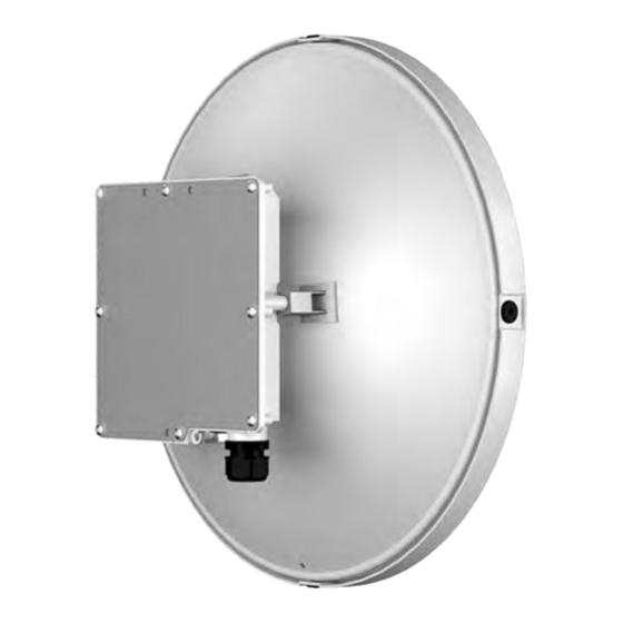
Page 65: Wibas G5 Connect+ Combo
WiBAS / WiBAS G5 Terminal Stations Installation & Cabling Manual - Edition 2.1 WiBAS G5 Connect+ Combo Introduction Apply this procedure for installing the following wireless equipment: WiBAS G5 Connect+ Combo Terminal radio unit WG5-CONN-PLUS-LB-UB with pre-mounted antenna 0.3 m (ANT-IS-2628-1F-C). ... - Page 66 4. Installation Procedures WiBAS G5 Connect+ Combo , Continued Pole installation WiBAS G5 Connect+ / Antenna / Mounting Kit overview WG5-CONN-PLUS-LB-UB ANT-IS-2628-1F-C WG5-CONN-PLUS-LB-UB ANT-IS-2628-1D6F-C WG5-WCONN-PL-MNT Pole Installation Overview with 0.3 m Antenna Pole Installation Overview with 0.5 m Antenna Continued on next page...
- Page 67 WiBAS / WiBAS G5 Terminal Stations Installation & Cabling Manual - Edition 2.1 WiBAS G5 Connect+ Combo , Continued Mounting kits packing WiBAS G5 Connect+ Details materials WG5-WCONN-PL-MNT Azimuth bracket (A). Elevation bracket (B). Pole bracket (C). ...
- Page 68 4. Installation Procedures WiBAS G5 Connect+ Combo , Continued Prerequisites For elevation adjustment there is an elevation degrees indicator at both sides of the mounting kit, as shown below. The bracket during installation should be installed in 0 degrees. During commissioning the proper elevation degrees will be applied.
- Page 69 WiBAS / WiBAS G5 Terminal Stations Installation & Cabling Manual - Edition 2.1 WiBAS G5 Connect+ Combo , Continued Do not grab, nor touch the antenna during lifting, turning or any handling of Precautions the terminal while the terminal is mounted on the pole, it may lead to damage of the antenna.
- Page 70 4. Installation Procedures WiBAS G5 Connect+ Combo , Continued The parabolic low profile antenna should NEVER be placed on a hard Precautions, continued surface. Handle the antenna with care and avoid the application of pressure on the antenna cover as this may lead to breakage of the antenna dipole.
- Page 71 WiBAS / WiBAS G5 Terminal Stations Installation & Cabling Manual - Edition 2.1 WiBAS G5 Connect+ Combo , Continued Procedure for How to install the WiBAS G5 Connect+ Combo to pole mounting kit WiBAS G5 (WG5-WCONN-PL-MNT), proceed as follows: Connect+ Combo Step Action...
- Page 72 4. Installation Procedures WiBAS G5 Connect+ Combo , Continued Procedure for WiBAS G5 Step Action Connect+ Set the antenna position as shown below: Combo continued DO NOT TURN the ANTENNA, as shown below: Continued on next page...
- Page 73 WiBAS / WiBAS G5 Terminal Stations Installation & Cabling Manual - Edition 2.1 WiBAS G5 Connect+ Combo , Continued Procedure for WiBAS G5 Connect+ Combo continued Step Action Mount the elevation bracket onto the radio unit and then install the respective set of mounting kit packing materials, as shown below: Do not over tighten the screws.
-
Page 74: Wibas-Connect Combo
4. Installation Procedures WiBAS-Connect Combo Introduction Apply this procedure for installing the following wireless equipment: WiBAS -Connect Combo Terminal radio unit CONN-OB-U-DSDS with pre-mounted antenna 0.3m (ANT-IS-2628-1F-C) or 0.5 m (ANT-IS-2628-1D6F-C). Terminal radio unit CONN-OB-U-DSDS-DP with pre-mounted antenna 0.3 m (ANT-DP-2628-1F-C) or 0.5 m (ANT-DP-2628-1D6F-C). - Page 75 WiBAS / WiBAS G5 Terminal Stations Installation & Cabling Manual - Edition 2.1 WiBAS-Connect Combo , Continued Pole installation WiBAS -Connect / Antenna / WiBAS -Connect (auto-polarization) overview Mounting kit / Antenna / Mounting Kit CONN-OB-U-DSDS CONN-OB-U-DSDS-DP ANT-IS-2628-1F-C ANT-DP-2628-1F-C CONN-OB-U-DSDS CONN-OB-U-DSDS-DP ANT-IS-2628-1D6F-C ANT-DP-2628-1D6F-C...
- Page 76 4. Installation Procedures WiBAS-Connect Combo , Continued Wall installation CONN-OB-U-DSDS-DP overview WCONN-PL-W-MNT-DP ANT-DP-2628-1F-C CONN-OB-U-DSDS-DP ANT-DP-2628-1D6F-C Overview with 0.3 m antenna Continued on next page...
- Page 77 WiBAS / WiBAS G5 Terminal Stations Installation & Cabling Manual - Edition 2.1 WiBAS-Connect Combo , Continued Mounting kits packing WiBAS -Connect Details materials WCONN-PL-MNT Azimuth bracket (A). Elevation bracket (B). Pole bracket (C). U-BOLT, M8 x 100 mm (D). ...
- Page 78 4. Installation Procedures WiBAS-Connect Combo , Continued Mounting kits packing WiBAS -Connect Details materials, (auto-polarization) continued WCONN-DP-PL-MNT Azimuth bracket (A). Elevation bracket (B). Pole bracket (C). U-BOLT, M8 x 100 mm (D). U-BOLT bracket (E). ...
- Page 79 WiBAS / WiBAS G5 Terminal Stations Installation & Cabling Manual - Edition 2.1 WiBAS-Connect Combo , Continued Mounting kits packing WiBAS -Connect Details materials, (auto-polarization) continued WCONN-PL-W-MNT-DP Azimuth bracket (A). Elevation bracket (B). Wall bracket (C). Set-A: ...
- Page 80 4. Installation Procedures WiBAS-Connect Combo , Continued Prerequisites For elevation adjustment there is an elevation degrees indicator at both sides of the mounting kit, as shown below. The bracket during installation should be installed in 0 degrees. During commissioning the proper elevation degrees will be applied.
- Page 81 WiBAS / WiBAS G5 Terminal Stations Installation & Cabling Manual - Edition 2.1 WiBAS-Connect Combo , Continued Do not grab, nor touch the antenna during lifting, turning or any handling of Precautions the terminal while the terminal is mounted on the pole, it may lead to damage of the antenna.
- Page 82 4. Installation Procedures WiBAS-Connect Combo , Continued Adjustable torque U-wrench. Tools Drilling machine (fitted with a 13 mm drill bit) for wall mount installation. Procedure for How to install the WiBAS -Connect Combo to pole mounting kit (WCONN- WiBAS- PL-MNT), proceed as follows: Connect...
- Page 83 WiBAS / WiBAS G5 Terminal Stations Installation & Cabling Manual - Edition 2.1 WiBAS-Connect Combo , Continued Procedure for WiBAS- Step Action Connect For installing the pole bracket onto the pole perform the Combo, respective actions A, B, C and D, as shown below. continued For installing the pole bracket onto the pole using hose clamps go to the next step.
- Page 84 4. Installation Procedures WiBAS-Connect Combo , Continued Procedure for WiBAS- Step Action Connect Pass through both clamps to pole bracket openings and then Combo, install the whole assembly onto the pole (taking into the continued account the caution below): Do not over tighten the warm screws. Adjust the tool for applying min / max tightening torque 5.5 / 7 Nm.
- Page 85 WiBAS / WiBAS G5 Terminal Stations Installation & Cabling Manual - Edition 2.1 WiBAS-Connect Combo , Continued Procedure for WiBAS- Step Action Connect Turn the antenna to determine the desirable polarization, as Combo, shown below. continued VERTICAL HORIZONTAL Continued on next page...
- Page 86 4. Installation Procedures WiBAS-Connect Combo , Continued Procedure for WiBAS- Step Action Connect Mount the elevation bracket onto the radio unit and then install Combo, the respective set of mounting kit packing materials, as shown continued below: Do not over tighten the screws. Adjust the tool for applying max tightening torque 5.5 Nm for M5 screws.
- Page 87 WiBAS / WiBAS G5 Terminal Stations Installation & Cabling Manual - Edition 2.1 WiBAS-Connect Combo , Continued Procedure for WiBAS- Step Action Connect Mount the elevation bracket onto the azimuth bracket and then Combo, install the respective set of mounting kit packing materials, as continued shown below: Do not over tighten the screws.
- Page 88 4. Installation Procedures WiBAS-Connect Combo , Continued Procedure for How to install the WiBAS -Connect auto-polarization Combo to pole WiBAS- mounting kit (WCONN-DP-PL-MNT) or to wall mounting kit (WCONN-PL- Connect (auto- W-MNT-DP), proceed as follows: polarization) Combo Step Action For pole mount installation, proceed as follows. For wall mount installation go to step 7.
- Page 89 WiBAS / WiBAS G5 Terminal Stations Installation & Cabling Manual - Edition 2.1 WiBAS-Connect Combo , Continued Procedure for WiBAS- Step Action Connect (auto- For installing the pole bracket onto the pole perform the polarization) respective actions A, B, C and D, as shown below. Combo, continued For installing the pole bracket onto the pole using hose...
- Page 90 4. Installation Procedures WiBAS-Connect Combo , Continued Procedure for WiBAS- Step Action Connect (auto- Pass through both clamps to pole bracket openings and then polarization) install the whole assembly onto the pole (taking into the Combo, account the caution below): continued Do not over tighten the warm screws.
- Page 91 WiBAS / WiBAS G5 Terminal Stations Installation & Cabling Manual - Edition 2.1 WiBAS-Connect Combo , Continued Procedure for WiBAS- Step Action Connect (auto- Set the antenna position as shown below: polarization) Combo, continued DO NOT TURN the ANTENNA, as shown below: Continued on next page...
- Page 92 4. Installation Procedures WiBAS-Connect Combo , Continued Procedure for WiBAS- Step Action Connect (auto- Mount the elevation bracket onto the radio and then install the polarization) respective set of mounting kit packing materials, as shown Combo, below: continued Do not over tighten the screws. Adjust the tool for applying max tightening torque 5.5 Nm for M5 screws.
- Page 93 WiBAS / WiBAS G5 Terminal Stations Installation & Cabling Manual - Edition 2.1 WiBAS-Connect Combo , Continued Procedure for WiBAS- Step Action Connect (auto- Mount the elevation bracket onto the azimuth bracket and then polarization) install the respective set of mounting kit packing materials, as Combo, shown below: continued...
- Page 94 4. Installation Procedures WiBAS-Connect Combo , Continued Procedure for WiBAS- Step Action Connect (auto- Perform the following actions: polarization) Attach the wall bracket into the wall surface. Combo, continued Install the respective set of mounting kit packing materials, as shown below.
- Page 95 WiBAS / WiBAS G5 Terminal Stations Installation & Cabling Manual - Edition 2.1 WiBAS-Connect Combo , Continued Procedure for WiBAS- Step Action Connect (auto- Mount the azimuth bracket onto the wall bracket and then polarization) install the respective set of mounting kit packing materials, as Combo, shown below.
- Page 96 4. Installation Procedures WiBAS-Connect Combo , Continued Procedure for WiBAS- Step Action Connect (auto- Set the antenna position, as shown in step 3. polarization) Combo, Mount the elevation bracket onto the radio and then install the continued respective set of mounting kit packing materials, as shown in step-4.
-
Page 97: Wibas-Connect And Low Profile 0.3 M / 0.5 M
WiBAS / WiBAS G5 Terminal Stations Installation & Cabling Manual - Edition 2.1 WiBAS-Connect and Low Profile 0.3 m / 0.5 m Introduction Apply this procedure for installing the following wireless equipment: WiBAS -Connect terminal radio unit (CONN-OB-U-DSDS). Low profile antennas 0.3 m (ANT-IS-2628-1F-C) / 0.5 m (ANT-IS-2628-1D6F-C). - Page 98 4. Installation Procedures WiBAS-Connect and Low Profile 0.3 m / 0.5 m , Continued Installation CONN-OB-U-DSDS CONN-OB-U-DSDS-DP overview ANT-IS-2628-1F-C ANT-DP-2628-1F-C ANT-IS-2628-1D6F-C ANT-DP-2628-1D6F-C WCONN-PL-MNT WCONN-DP-PL-MNT Continued on next page...
- Page 99 WiBAS / WiBAS G5 Terminal Stations Installation & Cabling Manual - Edition 2.1 WiBAS-Connect and Low Profile 0.3 m / 0.5 m , Continued Radio unit and CONN-OB-U-DSDS Details antenna WiBAS -Connect terminal radio unit. packing materials ANT-IS-2628-1F-C Details Low profile antenna 0.3 m – rectangular flange.
- Page 100 4. Installation Procedures WiBAS-Connect and Low Profile 0.3 m / 0.5 m , Continued Mounting kit packing WCONN-PL-MNT Details materials Azimuth bracket (A). Elevation bracket (B). Pole bracket (C). U-BOLT, M8 x 100 mm (D). U-BOLT bracket (E). ...
- Page 101 WiBAS / WiBAS G5 Terminal Stations Installation & Cabling Manual - Edition 2.1 WiBAS-Connect and Low Profile 0.3 m / 0.5 m , Continued Mounting kit packing WCONN-DP-PL-MNT Details materials, Azimuth bracket (A). continued Elevation bracket (B). Pole bracket (C). ...
- Page 102 4. Installation Procedures WiBAS-Connect and Low Profile 0.3 m / 0.5 m , Continued Prerequisites For elevation adjustment there is an elevation degrees indicator at both sides of the mounting kit, as shown below. The bracket during installation should be installed in 0 degrees. During commissioning the proper elevation degrees will be applied.
- Page 103 WiBAS / WiBAS G5 Terminal Stations Installation & Cabling Manual - Edition 2.1 WiBAS-Connect and Low Profile 0.3 m / 0.5 m , Continued Do not grab, nor touch the antenna during lifting, turning or any handling Precautions of the terminal while the terminal is mounted on the pole, it may lead to damage of the antenna.
- Page 104 4. Installation Procedures WiBAS-Connect and Low Profile 0.3 m / 0.5 m , Continued Tools Adjustable torque U-wrench. Procedure How to install the antennas 0.3 m or 0.5 m parabolic low profile to radio unit (CONN-OB-U-DSDS or CONN-OB-U-DSDS-DP) and then to pole mounting kit (WCONN-PL-MNT), proceed as follows: Step Action...
- Page 105 WiBAS / WiBAS G5 Terminal Stations Installation & Cabling Manual - Edition 2.1 WiBAS-Connect and Low Profile 0.3 m / 0.5 m , Continued Procedure, continued Step Action This step is related to radio unit CONN-OB-U-DSDS and antennas ANT-IS-2628-1F-C ANT-IS-2628- 1D6F-C.
- Page 106 4. Installation Procedures WiBAS-Connect and Low Profile 0.3 m / 0.5 m , Continued Procedure, continued Step Action This step is related to radio unit CONN-OB-U-DSDS- and antennas ANT-DP-2628-1F-C ANT-DP-2628- 1D6F-C. Follow the radio unit label, as shown below. DO NOT TURN the RADIO, as shown below: Continued on next page...
- Page 107 WiBAS / WiBAS G5 Terminal Stations Installation & Cabling Manual - Edition 2.1 WiBAS-Connect and Low Profile 0.3 m / 0.5 m , Continued Procedure, continued Step Action Install the feeder onto the radio wave guide, as shown below. Use the cross-headed screwdriver to install the four lock washers and screws.
- Page 108 4. Installation Procedures WiBAS-Connect and Low Profile 0.3 m / 0.5 m , Continued Procedure, continued Step Action Install the antenna reflector, as shown below. Use the cross-headed screwdriver to install the four lock washers and screws. Fully tighten. Do not over tighten. Continued on next page...
Need help?
Do you have a question about the WiBAS G5 Connect+ and is the answer not in the manual?
Questions and answers