Table of Contents
Advertisement
Advertisement
Chapters
Table of Contents

Related Manuals for Intracom WiBAS OSDR

Summary of Contents for Intracom WiBAS OSDR
- Page 1 Start Up & Commissioning Manual Edition 5.1 Confidential...
- Page 2 Information as well as drawings and specifications contained in this document are subject to change without prior notice. All trademarks and copyrights mentioned herein are the property of INTRACOM S.A. TELECOM SOLUTIONS and/or their respective owners. Any rights not expressly granted herein are reserved.
- Page 3 WiBAS OSDR-Hub & Terminal Station / WiBAS-Connect Terminal Station Start Up & Commissioning Manual - Edition 5.1 Document Revision History Previous Edition: Current Edition: Reasons of Change M = Modified, A = Added, R = Removed Details • Configuring Operational Parameters...
- Page 4 (Page intentionally left blank)
- Page 5 WiBAS OSDR-Hub & Terminal Station / WiBAS-Connect Terminal Station Start Up & Commissioning Manual - Edition 5.1 Equipment Disposal Disposal of old electrical and electronic equipment (applicable through the European Union and other European countries with separate waste collection systems).
- Page 6 WiBAS OSDR-Hub & Terminal Station / WiBAS-Connect Terminal Station Start Up & Commissioning Manual - Edition 5.1 Declaration of Conformity English Hereby, Intracom S.A. Telecom Solutions declares that the product WiBAS is CE marked in compliance with the essential requirements and...
-
Page 7: Table Of Contents
WiBAS OSDR-Hub & Terminal Station / WiBAS-Connect Terminal Station Start Up & Commissioning Manual - Edition 5.1 Table of Contents 1. Introduction ......................... 9 About this Document ......................9 Safety Precautions ......................11 About WiBAS-OSDR Hub / TS and WiBAS-Connect ............12 2. - Page 8 Table of Contents Appendix B – Inband Management Connection Troubleshooting ........89 Appendix C – Quality Indicator Thresholds ................ 93...
-
Page 9: Introduction
WiBAS OSDR-Hub & Terminal Station / WiBAS-Connect Terminal Station Start Up & Commissioning Manual - Edition 5.1 1. Introduction About this Document Scope of The scope of this document is to provide detailed instructions on the startup Document and commissioning of the following PtMP products: •... - Page 10 1. Introduction About this Document , Continued Conventions This document applies to the following conventions: • Arial Bold blue fonts are used for order codes. • Arial Blue underline fonts are used for document references. • Arial Bold black fonts are used for indicating important information or paragraph header.
-
Page 11: Safety Precautions
WiBAS OSDR-Hub & Terminal Station / WiBAS-Connect Terminal Station Start Up & Commissioning Manual - Edition 5.1 Safety Precautions Reference Before starting any commissioning works please follow the safety precautions as described to the following reference manuals: Product Reference Manuals Description Chapter No. -
Page 12: About Wibas-Osdr Hub / Ts And Wibas-Connect
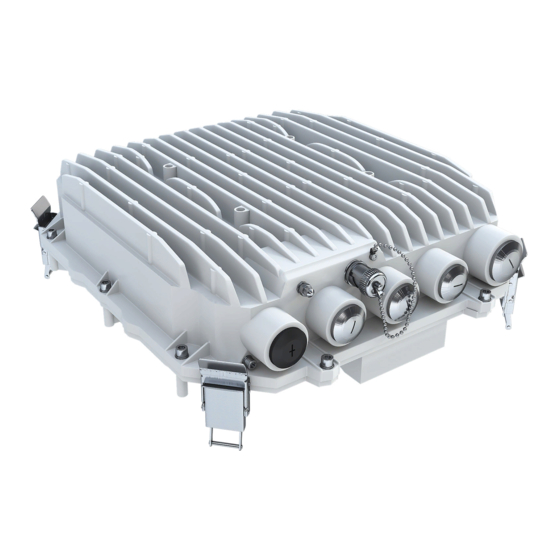
1. Introduction About WiBAS-OSDR Hub / TS and WiBAS-Connect Overview This document describes the startup & commissioning of the products shown below. The dimension of parabolic integrated antennas is indicative. For more information regarding antennas dimension please refer on page 9, item 4 of Reference manuals. -
Page 13: Before Starting The Commissioning
Start Up & Commissioning Manual - Edition 5.1 2. Before Starting the Commissioning Prior to starting the commissioning of a WiBAS OSDR-Hub or Terminal station and WiBAS-Connect , verify that the prerequisites mentioned below are fulfilled and all required HW / SW and mechanical tools are available. -
Page 14: Prerequisites
2. Before Starting the Commissioning Prerequisites Required Commissioning data at site should be entered according to Radio and commissioning Network planning. data The following commissioning data should be available before starting commissioning works on site: • RF planning values: expected RSSI, SNR, Modulation and Tx Power. •... - Page 15 WiBAS OSDR-Hub & Terminal Station / WiBAS-Connect Terminal Station Start Up & Commissioning Manual - Edition 5.1 Prerequisites , Continued Antenna • The antenna orientation of WiBAS –OSDR Hub should be carried out orientation toward the planned service area, as specified in the radio planning document.
-
Page 16: Hardware & Software Requirements
RSSI cable RSSI cable for antennas alignment (available by Intracom S.A Telecom Solutions). WiBAS-OSDR Hub / TS WiBAS -Connect For details on the compatible Web Browsers, please refer to Node Manager for WiBAS OSDR Reference Manual (Chapter 2, par. Log in). -
Page 17: Required Tools
WiBAS OSDR-Hub & Terminal Station / WiBAS-Connect Terminal Station Start Up & Commissioning Manual - Edition 5.1 Required Tools Tools Description Digital Voltmeter. For measuring: • Power injector input power. • The RSSI of radio unit during antennas alignment. Adjustable torque U-wrench (up to 19 mm... -
Page 18: Powering Up
On-site works (mentioned on page 14) have been carried out as instructed in the OSDR Installation & Cabling Manual. After interoperability confirmation by Intracom Telecom, other types of power injectors can also be used. 72 W POE also is applicable (POE-AC72-ID). -
Page 19: Powering Through Dc Power Injector
WiBAS OSDR-Hub & Terminal Station / WiBAS-Connect Terminal Station Start Up & Commissioning Manual - Edition 5.1 Powering through DC Power Injector Introduction DC power cable coming from the DC power injector must be connected to a DC Distribution Board. - Page 20 3. Powering Up Powering through DC Power Injector , Continued Procedure, Step Action continued This step shows the proper LED indication status when the DC power source is operating properly End of procedure. In case of any error, see Appendix A – LED Indications on page 19.
-
Page 21: Powering Through Ac Power Injector
WiBAS OSDR-Hub & Terminal Station / WiBAS-Connect Terminal Station Start Up & Commissioning Manual - Edition 5.1 Powering through AC Power Injector Powering up To power up a radio unit using an AC power injector, plug the AC power via AC power supply cable coming from the AC power injector to the AC power source. - Page 22 3. Powering Up Powering through AC Power Injector , Continued AC power AC power injector 75 W: injectors for In power-up, all three LEDs light for 2 sec, as part of the self-test process. WiBAS-OSDR Hub & TS Upon successful completion, the ON and CONNECT LEDs should be steady green.
-
Page 23: Physical Management Connection
WiBAS OSDR-Hub & Terminal Station / WiBAS-Connect Terminal Station Start Up & Commissioning Manual - Edition 5.1 4. Physical Management Connection Introduction This chapter describes all the available physical connections between radio unit and the laptop for management and commissioning purpose. -
Page 24: Wibas-Osdr Hub & Ts
4. Physical Management Connection 4.1. WiBAS-OSDR Hub & TS INBAND Management Connection (through GbE2 port) Connection The diagram below depicts the physical connection of the electrical GbE port diagram (GbE 2) of Hub or TS for inband management purpose when a power injector is used. -
Page 25: Inband Management Connection (Through Gbe1 Port)
WiBAS OSDR-Hub & Terminal Station / WiBAS-Connect Terminal Station Start Up & Commissioning Manual - Edition 5.1 INBAND Management Connection (through GbE1 port) Connection The diagram below depicts the physical connection of the electrical GbE port diagram (GbE 1) of Hub or TS for inband management purpose when a power... -
Page 26: Outband Management Connection
4. Physical Management Connection OUTBAND Management Connection Connection The diagram below depicts the physical connection of the electrical GbE port diagram (GbE 2) of Hub or TS for inband management purpose when a power injector is used. -
Page 27: Wibas-Connect Ts
WiBAS OSDR-Hub & Terminal Station / WiBAS-Connect Terminal Station Start Up & Commissioning Manual - Edition 5.1 4.2. WiBAS-Connect TS INBAND Management Connection Connection The diagram below depicts the physical connection of the electrical GbE1 diagram port for inband management purpose when a power injector is used. -
Page 28: Accessing A Radio Unit Via Node Manager
5. Accessing a Radio Unit via Node Manager 5. Accessing a Radio Unit via Node Manager Scope This chapter provides the necessary instructions to log in to WiBAS radio unit. Default IP Address Factory default The first time you access a radio unit , the default factory IP address (inband IP Addresses or outband) is required: •... -
Page 29: Accessing A Radio Unit
WiBAS OSDR-Hub & Terminal Station / WiBAS-Connect Terminal Station Start Up & Commissioning Manual - Edition 5.1 Accessing a Radio Unit Scope This paragraph described how to access a radio unit when management connection has been implemented through a power injector. -
Page 30: Equipment Commissioning
6. Equipment Commissioning 6. Equipment Commissioning Overview For WiBAS radio unit commissioning perform the procedures in the following order: Step Procedure / Topic See Page Performing Preliminary Actions Configuring Operational Parameters Antenna Alignment Checking Operation Service Provisioning Upon successful completion of the above procedures, the network operator will be able to take control and proceed to Ethernet QoS configuration and Ethernet provisioning. -
Page 31: Performing Preliminary Actions
WiBAS OSDR-Hub & Terminal Station / WiBAS-Connect Terminal Station Start Up & Commissioning Manual - Edition 5.1 6.1. Performing Preliminary Actions After successful connection with radio unit, the following actions should be performed on unit prior to starting any configuration:... -
Page 32: Configuring Operational Parameters
6. Equipment Commissioning 6.2. Configuring Operational Parameters WiBAS-OSDR Hub Procedure To configure the operational parameters of the WiBAS OSDR-HUB, please follow the steps below: Step Task See Reference Manuals item 3… Management How to change outband / inband IP Interfaces address refer to Chapter 5 / Paragraph “Configuring the Management Interfaces”. - Page 33 WiBAS OSDR-Hub & Terminal Station / WiBAS-Connect Terminal Station Start Up & Commissioning Manual - Edition 5.1 WiBAS-OSDR Hub , Continued Procedure, Step Task See Reference Manuals item 3… continued Site information How to add the site information refer to Chapter 5 / Paragraph “Adding Site...
-
Page 34: Wibas-Osdr Ts
6. Equipment Commissioning WiBAS-OSDR TS Procedure To configure the operational parameters of the WiBAS OSDR TS, please follow the steps below: Step Task See Reference Manuals item 3… Management How to change the outband / inband IP Interfaces address refer to Chapter 5 / Paragraph “Configuring the Management Interfaces”. - Page 35 WiBAS OSDR-Hub & Terminal Station / WiBAS-Connect Terminal Station Start Up & Commissioning Manual - Edition 5.1 WiBAS-OSDR TS , Continued Procedure, Step Task See Reference Manuals item 3… continued Site information How to add the site information refer to Chapter 5 / Paragraph “Adding Site...
-
Page 36: Wibas-Connect Ts
6. Equipment Commissioning WiBAS-Connect TS Procedure To configure the operational parameters of the WiBAS ,-Connect please follow the steps below: Step Task See Reference Manuals item 3… Management How to change the outband / inband IP Interfaces address refer to Chapter 5 / Paragraph “Configuring the Management Interfaces”. - Page 37 WiBAS OSDR-Hub & Terminal Station / WiBAS-Connect Terminal Station Start Up & Commissioning Manual - Edition 5.1 WiBAS-Connect TS , Continued Procedure, Step Task See Reference Manuals item 3… continued Site information How to add the site information refer to Chapter 5 / Paragraph “Adding Site...
-
Page 38: Wibas-Connect Ts (Auto-Polarization Edition)
6. Equipment Commissioning WiBAS-Connect TS (Auto-Polarization Edition) Procedure To configure the operational parameters of the WiBAS ,-Connect (auto- polarization edition) please follow the steps below: Step Task See Reference Manuals item 3… Management How to change the outband / inband IP address refer to Chapter 5 / Paragraph Interfaces “Configuring the Management Interfaces”. - Page 39 WiBAS OSDR-Hub & Terminal Station / WiBAS-Connect Terminal Station Start Up & Commissioning Manual - Edition 5.1 WiBAS-Connect TS (Auto-Polarization Edition) , Continued Procedure, Step Task See Reference Manuals item 3… continued Site information How to add the site information refer to Chapter 5 / Paragraph “Adding Site...
-
Page 40: Antenna Alignment
6. Equipment Commissioning 6.3. Antenna Alignment Introduction The section includes the following topics: Topic See Page WiBAS-OSDR Hub WiBAS-OSDR TS WiBAS-Connect TS WiBAS-Connect TS (Auto-Polarization Edition) WORKING ON THE BUILDING’S ROOF Precautions During stormy weather, do not perform any mechanical assembling or antenna installation/beaming works on the building’s roof. - Page 41 WiBAS OSDR-Hub & Terminal Station / WiBAS-Connect Terminal Station Start Up & Commissioning Manual - Edition 5.1 Antenna Alignment , Continued The RSSI (voltmeter reading) best value is defined as below: RSSI best value definition NEGATIVE sign RSSI: Example: The best value between -0.456 Vdc and -0.789 Vdc is: -0.456...
-
Page 42: Connect Rssi Cable
6. Equipment Commissioning Connect RSSI Cable RSSI cable To connect the RSSI cable into the radio unit receptacle, please follow the connection steps below: procedure Step Action WiBAS -OSDR Hub or Terminal Station: Locate the RSSI receptacle at WiBAS -OSDR Hub & TS connection panel. - Page 43 WiBAS OSDR-Hub & Terminal Station / WiBAS-Connect Terminal Station Start Up & Commissioning Manual - Edition 5.1 Connect RSSI Cable , Continued RSSI cable connection Step Action procedure, Connect the RSSI cable, as shown below. continued WiBAS -OSDR Hub and TS:...
-
Page 44: Wibas-Osdr Hub
6. Equipment Commissioning WiBAS-OSDR Hub Introduction This paragraph describes the antenna alignment for the following cases: Precaution Never leave unoccupied receptacles without cover. Covering receptacles is necessary to protect against humidity penetration. Prerequisite Please refer to item 1 of Reference manuals on page (Chapter 4 / Section 4.1 / Sectoral and Parabolic Antenna Procedure). -
Page 45: Wibas-Osdr Ts
WiBAS OSDR-Hub & Terminal Station / WiBAS-Connect Terminal Station Start Up & Commissioning Manual - Edition 5.1 WiBAS-OSDR TS Introduction This paragraph describes the antenna alignment for the following products: The relevant procedures can be found as follows: Procedure Name... - Page 46 6. Equipment Commissioning WiBAS-OSDR TS , Continued Mounting kit During commissioning the RF planning study azimuth and elevation degrees overview will be used as reference for antenna coarse alignment. Continued on next page...
- Page 47 WiBAS OSDR-Hub & Terminal Station / WiBAS-Connect Terminal Station Start Up & Commissioning Manual - Edition 5.1 WiBAS-OSDR TS , Continued Procedure for WiBAS-OSDR TS with Parabolic Integrated Antenna To perform WiBAS-OSDR TS parabolic integrated antenna alignment, please follow the steps...
- Page 48 6. Equipment Commissioning WiBAS-OSDR TS , Continued Procedure for WiBAS-OSDR TS with Parabolic Integrated Antenna, continued Step Action Perform fine alignment, as follows: Use the spanner key to loosen the azimuth adjustment bolts (A1). Perform azimuth • (A2) adjustment by rotating the bolts of the antenna mounting kit until the voltage readout reaches a desired level.
- Page 49 WiBAS OSDR-Hub & Terminal Station / WiBAS-Connect Terminal Station Start Up & Commissioning Manual - Edition 5.1 WiBAS-OSDR TS , Continued Procedure for WiBAS-OSDR TS with Parabolic Integrated Antenna, continued Step Action Log in to the aligned terminal station as described to Accessing a Radio Unit page 29.
- Page 50 6. Equipment Commissioning WiBAS-OSDR TS , Continued Procedure for To perform WiBAS-OSDR TS panel antenna alignment, please follow the WiBAS-OSDR steps below: TS with Panel Antenna Step Action Perform coarse alignment, as follows: Use the respective spanner key to rotate the assembly on the pole so that the antenna is “visually”...
- Page 51 WiBAS OSDR-Hub & Terminal Station / WiBAS-Connect Terminal Station Start Up & Commissioning Manual - Edition 5.1 WiBAS-OSDR TS , Continued Procedure for WiBAS-OSDR TS with Panel Antenna, continued Step Action Perform fine alignment, as follows: • Use the allen key to loosen the azimuth adjustment bolt (A). Perform azimuth adjustment by moving very slowly the whole system (within the ±10...
- Page 52 6. Equipment Commissioning WiBAS-OSDR TS , Continued Procedure for WiBAS-OSDR TS with Panel Antenna, continued Step Action Log in to the aligned terminal station as described to Accessing a Radio Unit page 29. Go to Summary and check the RSSI & SNR value, as shown below: Press the refresh button to get the latest value.
-
Page 53: Wibas-Connect Ts
WiBAS OSDR-Hub & Terminal Station / WiBAS-Connect Terminal Station Start Up & Commissioning Manual - Edition 5.1 WiBAS-Connect TS Introduction This paragraph describes the antenna alignment for the following products: The relevant procedures can be found as follows: Procedure Name... - Page 54 6. Equipment Commissioning WiBAS-Connect TS , Continued Precautions Never leave unoccupied receptacles without cover. Covering receptacles is necessary to protect against humidity penetration. Prerequisite During commissioning the azimuth and elevation values should be available by RF planning study. Continued on next page...
- Page 55 WiBAS OSDR-Hub & Terminal Station / WiBAS-Connect Terminal Station Start Up & Commissioning Manual - Edition 5.1 WiBAS-Connect TS , Continued Mounting kit During commissioning the RF planning study azimuth and elevation degrees overview will be used as reference for antenna coarse alignment.
-
Page 56: Procedure For Wibas-Connect Ts With Parabolic Integrated Antenna
6. Equipment Commissioning WiBAS-Connect TS , Continued Procedure for WiBAS-Connect TS with Parabolic Integrated Antenna To perform WiBAS-Connect TS parabolic integrated antenna alignment, please follow the steps below: Step Action Perform coarse alignment, as follows: Use the respective spanner key to rotate the assembly on the pole so that the antenna is “visually”... - Page 57 WiBAS OSDR-Hub & Terminal Station / WiBAS-Connect Terminal Station Start Up & Commissioning Manual - Edition 5.1 WiBAS-Connect TS , Continued Procedure for WiBAS-Connect TS with Parabolic Integrated Antenna, continued Step Action Perform fine alignment, as follows: Use the spanner key to loosen the azimuth adjustment bolts (A1). Perform azimuth •...
- Page 58 6. Equipment Commissioning WiBAS-Connect TS , Continued Procedure for WiBAS-Connect TS with Parabolic Integrated Antenna, continued Step Action Log in to the aligned terminal station as described to Accessing a Radio Unit page 29. Go to Summary and check the RSSI & SNR value, as shown below: Press the refresh button to get the latest value.
-
Page 59: Procedure For Wibas-Connect Ts With Panel Antenna
WiBAS OSDR-Hub & Terminal Station / WiBAS-Connect Terminal Station Start Up & Commissioning Manual - Edition 5.1 WiBAS-Connect TS , Continued Procedure for To perform WiBAS-Connect TS panel antenna alignment, please follow the WiBAS- steps below: Connect TS with Panel... - Page 60 6. Equipment Commissioning WiBAS-Connect TS , Continued Procedure for WiBAS-Connect TS with Panel Antenna, continued Step Action Perform fine alignment, as follows: • Use the spanner key to loosen the azimuth adjustment bolts (A). Perform azimuth adjustment by moving very slowly the whole system (within the ±10 range around the azimuth axis) until the voltage readout reaches a desired level.
- Page 61 WiBAS OSDR-Hub & Terminal Station / WiBAS-Connect Terminal Station Start Up & Commissioning Manual - Edition 5.1 WiBAS-Connect TS , Continued Procedure for WiBAS-Connect TS with Panel Antenna, continued Step Action Log in to the aligned terminal station as described to Accessing a Radio Unit page 29.
- Page 62 6. Equipment Commissioning WiBAS-Connect TS , Continued Procedure for To perform WiBAS-Connect TS parabolic low profile antenna alignment, WiBAS- please follow the steps below: Connect TS with Parabolic Low Profile Antenna Step Action Open the tool clamps (A & B) and mount the tool onto the radio unit respective holes, as shown below.
- Page 63 WiBAS OSDR-Hub & Terminal Station / WiBAS-Connect Terminal Station Start Up & Commissioning Manual - Edition 5.1 WiBAS-Connect TS , Continued Procedure for WiBAS-Connect TS with Parabolic Low Profile Antenna, continued Step Action Perform coarse alignment, as follows: Use the respective spanner key to rotate the assembly on the pole so that the antenna is “visually”...
- Page 64 6. Equipment Commissioning WiBAS-Connect TS , Continued Procedure for WiBAS-Connect TS with Parabolic Low Profile Antenna, continued Step Action Power on the terminal station. Connect the RSSI cable as described to RSSI cable connection procedure on page Continued on next page...
-
Page 65: Procedure For Wibas-Connect Ts With Parabolic Low Profile Antenna
WiBAS OSDR-Hub & Terminal Station / WiBAS-Connect Terminal Station Start Up & Commissioning Manual - Edition 5.1 WiBAS-Connect TS , Continued Procedure for WiBAS-Connect TS with Parabolic Low Profile Antenna, continued Step Action Perform fine alignment, as follows: • Use the spanner key to loosen the azimuth adjustment bolts (A). Perform azimuth adjustment by holding tool’s handles firmly and slightly move the antenna/radio... - Page 66 6. Equipment Commissioning WiBAS-Connect TS , Continued Procedure for WiBAS-Connect TS with Parabolic Low Profile Antenna, continued Step Action Perform fine alignment, as follows: • Use the spanner key to loosen the elevation adjustment bolts (E). Perform elevation adjustment by holding tool’s handles firmly and slightly move the antenna/radio combo (within the ±10 range around the elevation axis) until the...
- Page 67 WiBAS OSDR-Hub & Terminal Station / WiBAS-Connect Terminal Station Start Up & Commissioning Manual - Edition 5.1 WiBAS-Connect TS , Continued Procedure for WiBAS-Connect TS with Parabolic Low Profile Antenna, continued Step Action Log in to the aligned terminal station as described to Accessing a Radio Unit page 29.
-
Page 68: Wibas-Connect Ts (Auto-Polarization Edition)
6. Equipment Commissioning WiBAS-Connect TS (Auto-Polarization Edition) Introduction This paragraph describes the antenna alignment for the following product: The relevant procedure is provided on page Continued on next page... - Page 69 WiBAS OSDR-Hub & Terminal Station / WiBAS-Connect Terminal Station Start Up & Commissioning Manual - Edition 5.1 WiBAS-Connect TS (Auto-Polarization Edition) , Continued Precautions Never leave unoccupied receptacles without cover. Covering receptacles is necessary to protect against humidity penetration. Prerequisites •...
- Page 70 6. Equipment Commissioning WiBAS-Connect TS (Auto-Polarization Edition) , Continued Mounting kit During commissioning the RF planning study azimuth and elevation degrees overview will be used as reference for antenna coarse alignment. Continued on next page...
- Page 71 WiBAS OSDR-Hub & Terminal Station / WiBAS-Connect Terminal Station Start Up & Commissioning Manual - Edition 5.1 WiBAS-Connect TS (Auto-Polarization Edition) , Continued Procedure for -Connect auto-polarization radio unit TS parabolic low To perform WiBAS WiBAS- profile antenna alignment, please follow the steps below:...
- Page 72 6. Equipment Commissioning WiBAS-Connect TS (Auto-Polarization Edition) , Continued Procedure for WiBAS-Connect Auto-Polarization TS with Parabolic Low Profile Antenna, continued The following flowchart provides an overall work flow based on the steps described to the current procedure: Continued on next page...
- Page 73 WiBAS OSDR-Hub & Terminal Station / WiBAS-Connect Terminal Station Start Up & Commissioning Manual - Edition 5.1 WiBAS-Connect TS (Auto-Polarization Edition) , Continued Procedure for WiBAS-Connect Auto-Polarization TS with Parabolic Low Profile Antenna, continued Step Action Perform the following actions: •...
- Page 74 6. Equipment Commissioning WiBAS-Connect TS (Auto-Polarization Edition) , Continued Procedure for WiBAS-Connect Auto-Polarization TS with Parabolic Low Profile Antenna, continued Step Action Perform coarse alignment, as follows: Use the respective spanner key to rotate the assembly on the pole so that the antenna is “visually”...
- Page 75 WiBAS OSDR-Hub & Terminal Station / WiBAS-Connect Terminal Station Start Up & Commissioning Manual - Edition 5.1 WiBAS-Connect TS (Auto-Polarization Edition) , Continued Procedure for WiBAS-Connect Auto-Polarization TS with Parabolic Low Profile Antenna, continued Step Action Perform the following actions: •...
- Page 76 6. Equipment Commissioning WiBAS-Connect TS (Auto-Polarization Edition) , Continued Procedure for WiBAS-Connect Auto-Polarization TS with Parabolic Low Profile Antenna, continued Step Action Perform fine alignment, as follows: • Use the spanner key to loosen the azimuth adjustment bolts (A). Perform azimuth adjustment by holding tool’s handles firmly and slightly move the antenna/radio combo (within the ±10 range around the azimuth axis) until the voltage readout reaches a desired...
- Page 77 WiBAS OSDR-Hub & Terminal Station / WiBAS-Connect Terminal Station Start Up & Commissioning Manual - Edition 5.1 WiBAS-Connect TS (Auto-Polarization Edition) , Continued Procedure for WiBAS-Connect Auto-Polarization TS with Parabolic Low Profile Antenna, continued Step Action Perform the following actions: •...
- Page 78 6. Equipment Commissioning WiBAS-Connect TS (Auto-Polarization Edition) , Continued Procedure for WiBAS-Connect Auto-Polarization TS with Parabolic Low Profile Antenna, continued Step Action Perform fine alignment, as follows: • Use the spanner key to loosen the azimuth adjustment bolts (A). Perform azimuth adjustment by holding tool’s handles firmly and slightly move the antenna/radio combo (within the ±10 range around the azimuth axis) until the voltage readout reaches a desired...
- Page 79 WiBAS OSDR-Hub & Terminal Station / WiBAS-Connect Terminal Station Start Up & Commissioning Manual - Edition 5.1 WiBAS-Connect TS (Auto-Polarization Edition) , Continued Procedure for WiBAS-Connect Auto-Polarization TS with Parabolic Low Profile Antenna, continued Step Action The commissioner should compare the captured values from steps 4 and 6.
- Page 80 6. Equipment Commissioning WiBAS-Connect TS (Auto-Polarization Edition) , Continued Procedure for WiBAS-Connect Auto-Polarization TS with Parabolic Low Profile Antenna, continued Step Action If the values are the expected ones, then secure the antenna to the final position. Use the adjustable U-wrench to apply the final tightening torque to the bolts, as follows: •...
-
Page 81: Checking Operation
WiBAS OSDR-Hub & Terminal Station / WiBAS-Connect Terminal Station Start Up & Commissioning Manual - Edition 5.1 6.4. Checking Operation Hub procedure This paragraph describes how to check the WiBAS -OSDR Hub operation (taking in consideration that all commissioning works have been completed... - Page 82 6. Equipment Commissioning Checking Operation , Continued Terminal This paragraph describes how to check the WiBAS -OSDR TS or station WiBAS -Connect operation (taking in consideration that all commissioning procedure works have been completed successfully): Step Action Communicate with terminal station through inband. Go to Equipment Management >...
-
Page 83: Service Provisioning
WiBAS OSDR-Hub & Terminal Station / WiBAS-Connect Terminal Station Start Up & Commissioning Manual - Edition 5.1 6.5. Service Provisioning Overview Service provisioning is performed upon commissioning completion of the base station and terminal station as well. Procedure To perform service provisioning, please follow the steps below: Concerns to WiBAS …... - Page 84 6. Equipment Commissioning Service Provisioning , Continued Procedure, continued Concerns to WiBAS … WiBAS-OSDR Node Manager Step Task Manual Connect Bridge How to configure the bridge refer to chapter 6/6.2, paragraph √ √ √ “Configuring the Bridge”. L2 Ports How to configure the L2 ports refer to Chapter 6/6.2, paragraph √...
-
Page 85: Appendix A - Led Indications
WiBAS OSDR-Hub & Terminal Station / WiBAS-Connect Terminal Station Start Up & Commissioning Manual - Edition 5.1 Appendix A – LED Indications Radio unit LED The LED at the bottom of radio unit provides visual indications of the system status... - Page 86 Appendix A – LED Indications Appendix A – LED Indications , Continued Radio unit LED WiBAS -Connect status, continued Status of STAT LED System Condition Input power supply is absent. • Firmware upgrade Stable ON, green • Power up • Terminal is registered Blinking green •...
- Page 87 WiBAS OSDR-Hub & Terminal Station / WiBAS-Connect Terminal Station Start Up & Commissioning Manual - Edition 5.1 Appendix A – LED Indications , Continued POE-ID-AC35 LED Indication Description POWER LED Input power supply is absent. AC power OK. Overload (current limit).
- Page 88 Appendix A – LED Indications Appendix A – LED Indications , Continued PONE-OD-DC LED Indication Description Steady blue Normal operation. Blinking slow Input DC voltage is ok but radio unit is not present (at the (every 1 sec) injector's output). Blinking fast Power supply failure - overload, short circuit, under- (every 100 msec)
- Page 89 WiBAS OSDR-Hub & Terminal Station / WiBAS-Connect Terminal Station Start Up & Commissioning Manual - Edition 5.1 Appendix B – Inband Management Connection Troubleshooting Scope Appendix B provides the following fail-safe procedures: Fail-safe When used Physical Fail-safe IP procedure mngt...
- Page 90 Appendix B – Inband Management Connection Troubleshooting Appendix B – Inband Management Connection Troubleshooting , Continued Fail-safe Step Action procedure 1 (arp-s Enter the following static ARP cache entry and press ENTER: commands), Static ARP entry is not required when management continued VLAN is assigned as default VLAN on the connection port.
- Page 91 WiBAS OSDR-Hub & Terminal Station / WiBAS-Connect Terminal Station Start Up & Commissioning Manual - Edition 5.1 Appendix B – Inband Management Connection Troubleshooting , Continued The following procedure should be executed by a Windows 10 user, when Fail-safe procedure 2...
- Page 92 Appendix B – Inband Management Connection Troubleshooting Appendix B – Inband Management Connection Troubleshooting , Continued Fail-safe To apply fail-safe outband IP address, please follow the steps below: procedure 3 Prior to starting fail-safe procedure 3, ensure that an outband (outband) physical management connection has been implemented with WiBAS .
- Page 93 WiBAS OSDR-Hub & Terminal Station / WiBAS-Connect Terminal Station Start Up & Commissioning Manual - Edition 5.1 Appendix C – Quality Indicator Thresholds QI table The following table shows the quality indicator thresholds: QI THRESHOLD (Voltmeter reading) QI THRESHOLD Mode...
- Page 94 Intracom Telecom Regional Contacts Europe Iberia & LATAM Russia & CIS 19.7 km. Markopoulou Ave. Avenida Manoteras 8, Gate 4, 23 Novoslobodskaya Str., BC “Meyerhold” 19002 Peania, Athens Office 1K, 28050 Madrid Office 364, Moscow, 127055 Greece Spain Russia t: +30 2106671000...
Need help?
Do you have a question about the WiBAS OSDR and is the answer not in the manual?
Questions and answers