Table of Contents
Advertisement
Quick Links
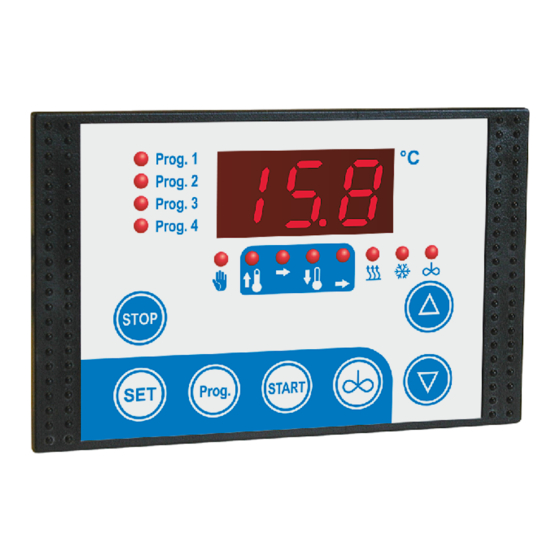
Freely programmable
pasteur controller
MRF-2-PA2
Installation and operating instructions
for plant engineering companies,
installers and service engineers
Firmware V1.3
106187 – MRF-2-PA2 -E - V1.3 - 24.01.2023
1. Introduction
Messen - Steuern - Regeln
alles aus einer Hand
Programmable via
configuration software
WELBA „KONSOFT"
Page 1
Advertisement
Table of Contents

Related Manuals for WELBA MRF-2-PA2


Summary of Contents for WELBA MRF-2-PA2
- Page 1 Messen - Steuern - Regeln alles aus einer Hand Freely programmable pasteur controller MRF-2-PA2 Installation and operating instructions for plant engineering companies, installers and service engineers Firmware V1.3 Programmable via configuration software WELBA „KONSOFT" Page 1 106187 – MRF-2-PA2 -E - V1.3 - 24.01.2023...
-
Page 2: Table Of Contents
1. Introduction Introduction ..............................4 Information about this operating instructions ................4 Limitation of liability ........................5 Warning notices in these operating instructions ................6 Model / type plate .......................... 7 Items supplied ..........................8 Disposal ............................8 Cleaning instructions ........................8 Dimensions ............................ - Page 3 General measures when using electronic control systems ............49 Publisher: Welba GmbH Fon: +49 (0)2638 / 9320-0 Electronic Control Engineering Fax: +49 (0)2638 / 9320-20 Gewerbepark Siebenmorgen 6 info@welba.de D-53547 Breitscheid www.welba.de Page 3 106187 – MRF-2-PA2 -E - V1.3 - 24.01.2023...
-
Page 4: Introduction
1.1 Information about this operating instructions These operating instructions are intended for the use by plant engineers, installers or service technicians of the MRF-2-PA2 pasteur regulator. This manual contains all necessary suggestions, information, recommendations and advice for the safe and proper installation and commissioning of the pasteur regulator. -
Page 5: Limitation Of Liability
Technical modifications Otherwise, our general terms and conditions as well as the terms of delivery of WELBA GmbH and the legal regulations valid at the time of conclusion of the con- tract are applicable. We reserve the right to make technical changes in the context of improving the prop- erties of use and further developments. -
Page 6: Warning Notices In These Operating Instructions
1. Introduction 1.3 Warning notices in these operating instructions Important safety information in these assembly instructions are identified by sym- bols. These instructions on occupational safety must be adhered to and followed. In these cases, behave particularly carefully in order to avoid accidents, personal injury and property damage. -
Page 7: Model / Type Plate
1. Introduction 1.4 Model / type plate These instructions apply to all controllers in the series MRF-2-PA2. The type designation and the exact connection diagram for your controller can be found on the controller as a connection sticker. Example: Controller type designation: Page 7 106187 –... -
Page 8: Items Supplied
1. Introduction 1.5 Items supplied Pasteur regulator MRF-2-PA2 Accompanying documentation Holder Rubber seal Temperature sensor TF1A-2 Fixing screws Optional accessories that may have been ordered 1.6 Disposal For the purposes of disposal, the device is classified as waste electronic equipment within the meaning of European Directive 2002/96/EC (WEEE) and must not be in- cluded with household waste. -
Page 9: Dimensions
1. Introduction 1.8 Dimensions Front panel cutout 87 x 56 mm Page 9 106187 – MRF-2-PA2 -E - V1.3 - 24.01.2023... -
Page 10: Technical Data Regulator
1. Introduction 1.9 Technical data regulator Operating voltage 230V AC +/-10%, 50/60 Hz Relay contact 1 changer contact, 2 make contacts, potential-free max. switching current 2 make contacts = 12A AC1 / 230V AC 1 changer contact = 10A AC1 / 230V AC max. -
Page 11: Sensor Dimensions Und Technical Data Sensor
Measurement range -10 .. 70° C Cable length standard 2 metres In contrast to our standard sensors, we also offer sensors with other sleeve shapes and diameters or other cable lengths. Page 11 106187 – MRF-2-PA2 -E - V1.3 - 24.01.2023... -
Page 12: Safety
2. Safety 2. Safety 2.1 General Information The plant engineering company, the installer or the service engi- WARNING neer must prepare operating instructions for the operator, taking account of the controller's parameters as supplied. We recommend referring only to the parameters which the end user needs for safe operation. -
Page 13: Intended Use
MFR-2-PA2. The regulator is fitted with a resistance temperature sensor. The pasteur regulator MRF-2-PA2 is not suitable for use in explosive atmospheres. Danger of explosion. Use only outside areas subject to explosive atmospheres. The regulator fulfils the EC requirements for electromagnetic compatibility (EMC) and the Low Voltage Directive (LVD). -
Page 14: Wiring, Screening, Earthing
2. Safety 2.3 Wiring, screening, earthing When selecting wiring materials and installing and connecting the temperature con- troller to the electricity supply, account must be taken of DIN VDE 0100 “Erection of power installations with rated voltages below 1000” or the relevant national regula- tions (e.g. -
Page 15: Installation
Attach the holding frame in the rear position as shown by the picture. Fasten the housing by using the screws provided. Front panel cut-out 87 x 56 mm Page 15 106187 – MRF-2-PA2 -E - V1.3 - 24.01.2023... -
Page 16: Fitting The Sensor
3. Installation 3.4 Fitting the sensor The sensor cable must not be chafed or kinked. WARNING There must be no substantial mechanical pressure on the sensor tube. Do not place the sensor and the high-voltage cable in the same cable conduit (not even within the switchbox). -
Page 17: Electrical Connection
No appliances with current levels in excess of the maximum val- ues indicated in the technical data should be connected to the relay contacts. No other consumers may be connected to the controller's mains terminals. Page 17 106187 – MRF-2-PA2 -E - V1.3 - 24.01.2023... -
Page 18: Procedure
Close the switchbox and turn on the mains voltage. The controller is now ready for parameterization. Parameterise the controller as described in the chapter 'Operation'. (possibly using the optional WELBA-KONSOFT configuration software). Page 18 106187 – MRF-2-PA -E - V1.3 – 24.01.2023... -
Page 19: Wiring / Circuit Diagram
Contactors are to be fitted with an RC protective circuit. See section 7.8. 4.3.1 Wiring the digital input Terminals "i1+i2" may only be connected to the potential at terminal "A1". Page 19 106187 – MRF-2-PA2 -E - V1.3 - 24.01.2023... -
Page 20: Operation
5. Operation 5. Operation 5.1 Function overview The freely programmable pasteur controller MRF-2-PA2 can be used either for 2- point or for PID control. It is designed for milk pasteurization, the production of cheese, yoghurt, etc. STAND-BY If all LEDs below the display are off, the controller is in 'standby'. All relays have dropped out, no control functions are active. - Page 21 By pressing the "STOP" button for approx. 3 seconds, a running program sequence or manual operation is aborted. The controller switches to 'standby'. Alternatively, depending on the parameterization, a running program can be aborted via the digital input. Page 21 106187 – MRF-2-PA2 -E - V1.3 - 24.01.2023...
-
Page 22: The Configuration Software Konsoft
NOTICE use. Despite all care, we point out that the use of the free PC-Software is at your own risk. WELBA does not accept any liability for damages or loss of data resulting from the installation or use of the Software. -
Page 23: Operation In Levels
5.3 Operation in levels The working level is used for operation and control in everyday operation. The MRF-2-PA2 is parameterized in 4 different parameter levels. The subordinate parameter levels are only entered after entering a code in order to NOTICE avoid inadvertent adjustment of the parameters. -
Page 24: Operation Of Working Level
5. Operation 5.4 Operation of working level Working level Code 212 Code 0E5 Code 345 Code 789 Code 384 Temperatures and Program sequence Control Hardware sequence settings configuration parameter configuration I/O test parameter C parameter P parameter r parameter A parameter o. -
Page 25: Operation In General
(depending on parameterization) the operator is asked about the fill level in the tub. See section 5.4.3 Page 25 106187 – MRF-2-PA2 -E - V1.3 - 24.01.2023... -
Page 26: Selection "Filling Quantity In %" Before Program Start
5. Operation 5.4.3 Selection "FILLING QUANTITY in %" before program start If the parameters are set accordingly [parameters P16, P26, P36, P46 = 5], a pro- gram can query the fill level in the tub after it has started. The heating and cooling process is then carried out according to the tank level. -
Page 27: Program Sequence With (Control) Phases
NOTE: Depending on the configuration, "End" is displayed at the beginning or at the end of "Holding phase 2"! The program is ended by pressing the "STOP" button (or via the digital input). The controller is now back in 'standby'. Page 27 106187 – MRF-2-PA2 -E - V1.3 - 24.01.2023... - Page 28 5. Operation In the C parameters, you determine the actual program flow through meaningful pa- rameterization. If individual dead or hold times are parameterized to '0' here, these phases are not executed. Depending on the target temperature selected, the heating and cooling phases can also be deactivated.
-
Page 29: Manual Operation
The target temperature can be changed before and during the entire manual opera- tion. Press and hold the SET button, Use the arrow keys to set the target temperature, Release the SET button. Page 29 106187 – MRF-2-PA2 -E - V1.3 - 24.01.2023... -
Page 30: Parameterization
6. Parameterization 6. Parameterization 6.1 Change and save parameters The MRF-2-PA2 is configured in 5 different parameter levels. In order to change parameters in one of the lower levels, the corresponding 'level code' must be entered. Working level Code 212... -
Page 31: Display And Change Parameter Value
The controller switches to standby. Back without saving the values: NOTICE If no button is pressed for 60 seconds: The controller automatically switches back to standby. All changes are lost. Page 31 106187 – MRF-2-PA2 -E - V1.3 - 24.01.2023... -
Page 32: Level "Temperatures And Expiry Times" (C Parameters)
6. Parameterization 6.2 Level "Temperatures and expiry times" (C parameters) Working level Code 0E5 Code 212 Code 345 Code 789 Code 384 Temperatures and Program sequence Control Hardware sequence settings configuration parameter configuration I/O test parameter C parameter P parameter r parameter A parameter o. -
Page 33: Level "Sequence Program Configuration (P Parameters)
Parameters are set here in which control phases the agitator is to be switched on. See section 7.7 Display: Done 0 .. 1 0: End of "Holding phase 2“ 1: Start of "Holding phase 2" (directly after cooling down) Page 33 106187 – MRF-2-PA2 -E - V1.3 - 24.01.2023... - Page 34 6. Parameterization to section 6.3: Level “sequence program configuration” (P parameters) Configuration program 2 Range Default 0 .. 4 P20* Program selection * With the "manual opera- tion" setting (selection 3 0: disabled or 4), some parameters 1: automatic program run, no setpoint change possible in the working level 2: automatic program run, setpoint change possible in the working level are hidden in the C pa- 3:* Manual operation HEATING - Setpoint change possible before and during heating...
- Page 35 Parameters are set here in which control phases the agitator is to be switched on. See section 7.7 Display: Done 0 .. 1 0: End of "Holding phase cooling down“ 1: Start of "Holding phase cooling down“ (immediately after cooling down) Page 35 106187 – MRF-2-PA2 -E - V1.3 - 24.01.2023...
- Page 36 6. Parameterization to section 6.3: Level “sequence program configuration” (P parameters) Configuration program 4 Range Default 0 .. 4 P40* Program selection * With the "manual opera- tion" setting (selection 3 0: disabled or 4), some parameters 1: automatic program run, no setpoint change possible in the working level are hidden in the C pa- 2: automatic program run, setpoint change possible in the working level rameters for program 4.
-
Page 37: Level "Control Parameter" (R Parameters)
Improper parameterization can lead to undesirable malfunctions and damage WARNING to the connected components. If you have any questions about parameterization, please contact the Welba tech- nical department. 6.4.1 Explanation of the control parameter sets Contents The pasteurizer controller MRF-2-PA2 has 8 independent "control parameter sets"... -
Page 38: Selection "Filling Quantity In %" In The Working Level
6. Parameterization 6.4.2 Selection "FILLING QUANTITY in %" in the working level With some products or manufacturing processes, it can be important to use different "control parameter sets" (in this case: power levels) for different filling levels in the tank. For example, a program can be assigned in the parameters [P16, P26, P36 and P46] with the selection '5': 'Filling quantity (power level)' query after pressing the START button... -
Page 39: Control Parameter Sets Warm Up
Tn (I part = reset time) 0…999 sec. r43 Tv (D part = hold-back time) 0…999 sec. r44 Ta (cycle time) 1…60 sec. r45 Minimum on/off time per cycle 0,1…5,0 sec. Page 39 106187 – MRF-2-PA2 -E - V1.3 - 24.01.2023... -
Page 40: Control Parameter Sets Cooling Down
6. Parameterization 6.4.1 Control parameter sets COOLING DOWN Control parameter set COOLING DOWN 1 Range Default (or 100%) r50 Hysteresis (with 2-point control) 0,1…10,0 r51 Xp (Ppart = proportional range) 0,1…99,9 K 10,0 r52 Tn (I part = reset time) 0…999 sec. -
Page 41: Level "Hardware Configuration" (A Parameters)
1 .. 3 1: 9600 2: 19200 3: 38400 Range Default Sensor type setting A98 Sensor type setting 0 .. 3 0: KTY 81-210 1: PT100 2: PT1000 3: KTY 81-110 Page 41 106187 – MRF-2-PA2 -E - V1.3 - 24.01.2023... -
Page 42: Level "I/O Test Parameter" (O. Parameters)
6. Parameterization 6.6 Level “I/O test parameter” (o. parameters) Working level Code 212 Code 345 Code 0E5 Code 789 Code 384 Temperatures and Program sequence Control Hardware sequence settings configuration parameter configuration I/O test parameter C parameter P parameter r parameter A parameter o. -
Page 43: Other Notes
In addition, the LED "Prog." and the LED "Manual operation" are displayed flashing. All relay outputs are reset. Fault resets itself when it is no longer present. Manual mode is automatically restarted. Page 43 106187 – MRF-2-PA2 -E - V1.3 - 24.01.2023... -
Page 44: Behaviour In The Event Of A Power Failure
7. Other Notes 7.1.2 Behaviour in the event of a power failure Fault code Fault Mains interruption during a program run After the mains voltage returns: The fault code "F30" is displayed flashing In addition, the LED "Prog." and the LED for the "Program phase"... -
Page 45: Functions Digital Input
Press and hold the Up and Down arrow keys simultaneously: The settings are saved. Adjust sensor 2 (if present) in the same way. Here the parameters [c92 and c93] must be set. Page 45 106187 – MRF-2-PA2 -E - V1.3 - 24.01.2023... -
Page 46: Temperature Control During Holding Times
7. Other Notes 7.4 Temperature control during holding times Holding time 1 During hold time 1 (phase 3), the controller keeps the set target temperature con- stant. The controller heats up if necessary. Holding time 2: Outside temperature higher than cooling down temperature After cooling down, the controller keeps the set target temperature constant during hold time 2 (phase 5). -
Page 47: End' Message On The Display
(e.g. to control a warning light). 7.6 Interface RS485 The controller has an RS485 interface as a connection option for a PC with the Welba Konsoft (see section 5.2) for parameterizing, updating and reading out the data. Page 47... -
Page 48: Determination Of The Agitator Activation Per Control Phase
7. Other Notes 7.7 Determination of the agitator activation per control phase In all four programs of the controller, it can be determined for each phase whether the stirrer should be activated or not. This setting is made in parameters [P17, P27, P37 and P47] The setting for this is binary coded. -
Page 49: General Measures When Using Electronic Control Systems
switching off inductive loads (contactors, motors, solenoid valves, etc.) unsatisfactory routing of wires, too small cross-sections loose contacts rhythmically changing power stages (power converters) power breakers high-frequency generators Page 49 106187 – MRF-2-PA2 -E - V1.3 - 24.01.2023... - Page 50 7. Other Notes to section 7.8: General measures when using electronic control systems b. If specific interference sources cannot be avoided they should at least be kept at a distance from the regulator system. c. Capacitive and inductive couplings can cause crosstalk between high-voltage lines and parallel low-voltage and sensor lines.
- Page 51 The suggested measures have the advantage that they will increase the lifetime of the devices as lower induction voltages (reduced spark formation) will also reduce contact burn. Page 51 106187 – MRF-2-PA2 -E - V1.3 - 24.01.2023...
Need help?
Do you have a question about the MRF-2-PA2 and is the answer not in the manual?
Questions and answers