Table of Contents
Advertisement
Quick Links
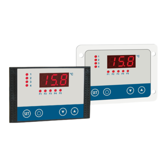
Programmable PID multichannel
temperature controller
MRF-2 ...
MRH-2 ...
Installation and operating instructions
for plant engineering companies
Software version V2.4
104781 - MRF-2 | MRH-2 - V2.4 - 22.07.2020
Measuring - Controlling - Regulating
Programmable via
configuration software
WELBA „KONSOFT"
1. Introduction
All from the same source
Page 1
Advertisement
Table of Contents

Related Manuals for WELBA MRF-2 Series


Summary of Contents for WELBA MRF-2 Series
- Page 1 Programmable PID multichannel All from the same source temperature controller MRF-2 ... MRH-2 ... Installation and operating instructions for plant engineering companies Software version V2.4 Programmable via configuration software WELBA „KONSOFT" Page 1 104781 - MRF-2 | MRH-2 - V2.4 - 22.07.2020...
- Page 2 1. Introduction Publisher: Welba GmbH Electronic Control Engineering Gewerbepark Siebenmorgen 6 D-53547 Breitscheid Fon: +49 (0)2638 / 9320-0 Fax: +49 (0)2638 / 9320-20 info@welba.de www.welba.de Page 2 104781 - MRF-2 | MRH-2 - V2.4 - 22.07.2020...
-
Page 3: Table Of Contents
1. Introduction Content Introduction ..............................4 Information about this operating instructions ................. 4 Limitation of liability ........................5 Appliance description ........................6 Model / type plate ........................... 7 Items supplied ..........................8 Disposal ............................8 Cleaning instructions ........................8 Dimensions ............................. 9 Technical data .......................... -
Page 4: Introduction
1. Introduction 1. Introduction 1.1 Information about this operating instructions These operating instructions are intended for the use by plant engineers, installers or service technicians of the MRF-2 | MRH-2 PID multichannel temperature control- ler. This manual contains all necessary suggestions, informations, recommendations and advice for the safe and proper installation and commissioning of the controller. -
Page 5: Limitation Of Liability
Technical modifications Otherwise, our general terms and conditions as well as the terms of delivery of WELBA GmbH and the legal regulations valid at the time of conclusion of the contract are applicable. We reserve the right to make technical changes in the context of improving the pro-... -
Page 6: Appliance Description
A type RS-485 interface is provided for communication with higher-level systems. WELBA “KONSOFT” The configuration software available as an option offers a simple way to set parame- ters and update the temperature controller. The values measured by the three sen- sors, the analogue input and the analogue output control signal can be transmitted to a PC. -
Page 7: Model / Type Plate
1. Introduction 1.4 Model / type plate These instructions apply to all controllers in the series MRF-2 | MRH-2. They contain detailed descriptions for operation and parameter setting for all variants. The type designation and the exact connection diagram for your controller can be found on the controller as a connection sticker. -
Page 8: Items Supplied
Holder Rubber seal Fixing screws Accompanying documentation Software “WELBA-KONSOFT” (optional) 1.6 Disposal For the purposes of disposal, the device is classified as waste electronic equipment within the meaning of European Directive 2002/96/EC (WEEE) and must not be in- cluded with household waste. It must be disposed of through the correct channels. -
Page 9: Dimensions
1. Introduction 1.8 Dimensions MRF-2 °C Panel cutout 87 x 56 mm MRH-2 °C Panel cutout 87,5 x 66,5 mm Pin size welding studs M3 96 x 53 mm Page 9 104781 - MRF-2 | MRH-2 - V2.4 - 22.07.2020... -
Page 10: Technical Data
1. Introduction 1.9 Technical data Operating voltage see circuit diagram sticker Relay contact depending on device - see circuit diagram sticker max. switching current depending on device - see circuit diagram sticker max. switching voltage depending on device - see circuit diagram sticker Display 13 mm LED-Display, 3 digits Display range... -
Page 11: Safety
2. Safety 2. Safety 2.1 General Information The plant engineering company must prepare operating instructions WARNING for the operator, taking account of the controller's parameters as supplied. We recommend referring only to the parameters which the end user needs for safe operation. In preparing the operating instructions for the end user, especially the chapter on “Safety”, account must be taken of local regulations. - Page 12 2. Safety These operating instructions contain important technical and safety in- WARNING formation. Please read carefully before installation and before any work on or with the regulator. It is the duty of the party commissioning the system to ensure compli- ance with the following guidelines.
-
Page 13: Intended Use
2. Safety 2.2 Intended use Programmable PID multichannel temperature controllers are intended for use in in- dustrial systems. They are designed to control heating systems, condensing units, alarms, fans, etc. Any other use of the device is permitted only with prior written permission from the manufacturer. -
Page 14: Wiring, Screening, Earthing
2. Safety 2.3 Wiring, screening, earthing When selecting wiring materials and installing and connecting the temperature con- troller to the electricity supply, account must be taken of DIN VDE 0100 “Erection of power installations with rated voltages below 1000” or the relevant national regulati- ons (e.g. -
Page 15: Installation
3.2 Unpacking and storage If the packaging is damaged or something is missing, do not fit the temperature con- troller. In this case please contact Welba. If you keep the temperature controller for a period before using it, store it in a clean dry place at a temperature of between -20°C and +70°C. -
Page 16: Fitting The Sensor
3. Installation MRH-2 For fixing the housing please follow the instructions: Place the seal carefully in the groove. Ensure it is not twisted. Push the housing onto the stud bolts from behind. Fasten the housing by using the hex nuts provided.. Panel cutout 87,5 x 66,5 mm Pin size welding studs M3... -
Page 17: Electrical Connection
Close the switchbox and turn on the mains voltage. Switch on the temperature controller and set the parameters (possibly using the optional WELBA-KONSOFT configuration software). Disconnect the system from the mains and open the switchbox. Plug the pre-cabled plug-in terminals of the components into the controller. -
Page 18: Wiring
4. Electrical connection 4.3 Wiring Correct wiring in accordance with the information in the accompanying description and local regulations is essential. Take particular care to ensure that the AC supply is not connected to the sensor input or other low-voltage inputs or outputs. The various relay contacts may only be connected with uniform tension. -
Page 19: Operation
TIP: WELBA „KONSOFT" The configuration software available as an option can be used to set and update the temperature controller's parameters. The values measured by the three sensors, the... -
Page 20: Etemcontroller Overview
5. Operation 5.2 Controller overview Relay outputs For directly controlling control contactors (pumps, compressors, heaters, etc.) 'Compressor rotation' or 'hot gas bypass' pro- grammable. High-pressure monitor: Functional safety en- sured even in the event of a microprocessor fault (meeting legal requirements.) Power supply: Variant A: 230 V ~ Variant F: 24 V -/=... -
Page 21: Controls / Displays
5. Operation 5.3 Controls / Displays 5.3.1 Meaning of LED’s LEDdisplay In [C97] defines which input is dis- played in the working level. LED’s 1 - 4 indicate the switching sta- tus of Relays 1 - 4 (if available) LED’s F1 - F5 indicate the switching sta- tus of the digital inputs. -
Page 22: Controller Architecture
5. Operation 5.4 Controller architecture The MRF-2 | MRH-2 includes: 4 separate and independent thermostat - hereafter called "controller blocks“. 2 function blocks "Temperature alarms" 5 function blocks for digital inputs. All blocks and functions can be set via the parameterization and are linkable. MRF-2 | MRH-2 INPUTS OUTPUTS... -
Page 23: Explanation Of Controller And Function Blocks
5. Operation 5.4.1 Explanation of controller and function blocks Explanation controller block 1 + 2 Parameter [P11 + P12] you determine: Controller block 1 [P11] may be: - 2-step-regulation which type of control - 2-step-regulation - PID pulsed - PID pulsed - PID analogue - PID analogue INPUTS... - Page 24 5. Operation Explanation function block digital input 1 + 5 Function digital input 1 .. 5 [H21 - H25] May be: - act directly on relays - switch setpoint - act on controller block - collective fault message - switching regulator in standby (may be): INPUTS (may be):...
-
Page 25: The Quick Way To Set Parameters
5. Operation 5.5 The quick way to set parameters The general rule is to determine the following before setting parameters: Which components (pumps, compressors, heaters, fans, alarms etc.) do you wish to control or regulate with the controller? Which factors (temperatures or external events) are decisive for controlling the connected appliances? ... -
Page 26: Parameter Quick-Guide
5. Operation 5.6 Parameter Quick-Guide Function block temp. alarm 1 Function block temp. alarm 1 H3 - H4 H5 - H6 Controller block 1 analogue Controller block 2 P21 - P25 P11 - P14 Controller block 3 P21 - P25 analogue Controller block 4 H21 - H25... -
Page 27: Parameter Levels
5. Operation 5.7 Parameter levels The operation of the controller is carried out in different operating levels: Working level ... is for everyday operation by the end user. Auf The display permanently shows the temperature as currently measured. The “SET“ button can be used to display and, in conjunction with the arrow buttons, to change target temperatures that have been set. -
Page 28: Operation Of Parameter Levels
5. Operation 5.7.1 Operation of parameter levels Programming Configuration Hardware Working level level + option level configuration Level When C99 or H99 reaches: - Release up arrow code - Press up arrow for 3 seconds - PA appears in the display 3 sec. -
Page 29: Parameter Lists
5. Operation 5.8 Parameter lists 5.8.1 C- parameters (Programming level) Description Range Default Full list of parameters. Setpoint 1 for controller block 1 - [P11] -99°C .. +400°C 15,0 Setpoint 2 for controller block 2 - [P12] -99°C .. +400°C 15,0 Depending on control- Setpoint 3 for controller block 3 - [P13]... - Page 30 5. Operation Description Range Default C30* Lower limit temperature -99°C .. 400°C 15,0 Lower limiting of difference temperature control. (Switchover to absolute value control when reached). C31* Upper limit temperature -99°C .. 400°C 32,0 Upper limiting of difference temperature control. (Switchover to absolute value control when reached).
-
Page 31: P- Parameters (Configuration Level)
5. Operation 5.8.2 P- parameters (configuration level) Description Range Default Full list of parameters. Switch mode controller block 1 0 .. 1 Switch mode controller block 2 0 .. 1 Depending on control- Switch mode controller block 3 0 .. 1 ler type and parameter Switch mode controller block 4 0 .. - Page 32 5. Operation Description Range Default The control types defined Controller block 3 for Setpoint C3 (2-step-control) 0 .. 12 here take effect only when Controller block 4 for Setpoint C4 (2-step-control)) 0 .. 12 they are assigned to the de- sired outputs [P21 ..
- Page 33 5. Operation Description Range Default P27 Function analog output (optional) 0 .. 6 1: connected to controller block 1 2: connected to controller block 2 3: connected to controller block 1 inverted function 4: connected to controller block 2 inverted function 5: connected to controller block 1 and 2.
- Page 34 5. Operation Description Range Default Min. adjustable value für hysteresis 1 below 0,1K .. 99,9 K Max. adjustable value für hysteresis 1 up 0,1K .. 99,9 K Min. adjustable value für hysteresis 2 below 0,1K .. 99,9 K Max. adjustable value für hysteresis 2 up 0,1K ..
-
Page 35: H- Parameter (Option Level)
5. Operation 5.8.3 H- parameter (option level) Description Range Default Kind of temperature alarm 1 0 .. 5 Full list of parameters. Kind of temperature alarm 2 0 .. 5 Depending on control- When an alarm with relative limits is selected, the parameter values set for the upper and ler type and parameter lower alarm limits always relate to the assigned setpoint. - Page 36 5. Operation Description Range Default Hysteresis temperature alarm 1 0,1 .. 5K Hysteresis temperature alarm 2 0,1 .. 5K Switch-on delay temperature alarm 1 0 .. 999 sec. Switch-on delay temperature alarm 2 0 .. 999 sec. Period for which alarm event must exist for alarm to be triggered. Activation delay for temperature alarm 1* 0 ..
- Page 37 5. Operation Description Range Default Compressor protection (time relay function) 0 .. 3 Assignment of blocking time in case of switch-off by digital input or temperature alarm. Blocking time see [H28]] disabled applies to relay 1 applies to relay 2 applies to relay 1 and relay 2 Compressor blocking time 0 ..
- Page 38 5. Operation Description Range Default Display when DOWN button pressed 0 .. 4 Display when UP button pressed 0 .. 4 in working level disabled sensor 1 sensor 2 sensor 3 analogue input Display text in standby (OFF) mode 0 .. 2 0 = no text 1 = AUS 2 = OFF...
-
Page 39: D- Parameter (Hardware Configuration)
5. Operation 5.8.4 d- parameter (hardware configuration) Description Range Default Activation sensor 2 0 .. 1 Full list of parameters. Activation sensor 3 (optionally) 0 .. 1 Depending on control- disabled ler type and parameter enabled configuration, certain parameters may be hidden. - Page 40 5. Operation Kind of sensor 0 .. 3 Setting applies to all connected sensors! KTY81/210 PT100 PT1000 KTY81/110 Minimum switch-on time/ Minimum switch-off 1 .. 20 time in pulsed PID operation Serves to reduce the frequency of switching during the cycle time, so as not to operate any slower control elements (e.g.
- Page 41 5. Operation Independence fault report relay 1 .. 3 If activated, the fault message function and its LED display remain OFF and / or standby. disabled. The relay switches off at OFF or standby. Independent of OFF (via button). The relay only switches off during standby (via digital input). Independent of standby (via digital input).
-
Page 42: Other Information
6. Other information 6. Other information 6.1 Setting the actual value correction A correction can be made to the value as measured by the sensor, which applies cumulatively over the entire measuring range. This is necessary when: at the first installation, ... -
Page 43: Fault Indication
6. Other information 6.2 Fault indication Faults in the regulator are indicated by a flashing display as follows: LED - Display Fault F1L* Sensor short circuit: F2L* The sensor or sensor cable is faulty and must be replaced or repaired. Parameter [C91] "Actual value correction" must then F3L* be adjusted at programming level. -
Page 44: General Measures When Using Electronic Control Systems
6. Other information 6.3 General measures when using electronic control systems So that even complicated regulatory tasks can be presented to the user in a manner which is clear and simple and ensures high measurement accuracy, today's electro- nic control systems make increasing use of microprocessors. However, the benefits of these systems are countered by the disadvantage that increased measurement accuracy is accompanied by sensitivity to interference. - Page 45 6. Other information b. If specific interference sources cannot be avoided they should at least be kept at a distance from the regulator system. c. Capacitive and inductive couplings can cause crosstalk between high-voltage lines and parallel low-voltage and sensor lines. This distorts measured values and signals and can disrupt the entire regulatory process.
- Page 46 6. Other information Semiconductor switches such as thyristors or triacs also produce interference voltages. They occur as a result of non-linear characteristics and finite ignition voltages. These components must be protected against excessive voltages, for which mainly varistors, RC combinations or choke coils are used. The use of zero-voltage switches is also recommended.
Need help?
Do you have a question about the MRF-2 Series and is the answer not in the manual?
Questions and answers