Table of Contents
Advertisement
Available languages
Available languages
Quick Links
For use in all Logic 5.0 commercial door operators.
INSTALLATION
DO NOT connect the power or activate the operator until instructed
to do so.
REMOVE THE EXISTING LOGIC BOARD
1. Disconnect power from the operator.
2. Disconnect all wires from the board:
•
Control Wiring Terminal Block
•
System Wiring Connector (J3)
•
Coaxial antenna
NOTE: Remember the location of all wiring connections for
reinstallation.
3. Remove option boards on slots 1 and/or 2 (if present).
4. Disconnect the yellow Current Sense wire (if present).
5. Remove the logic board from its four mounting posts using
needle nose pliers or a fl athead screwdriver.
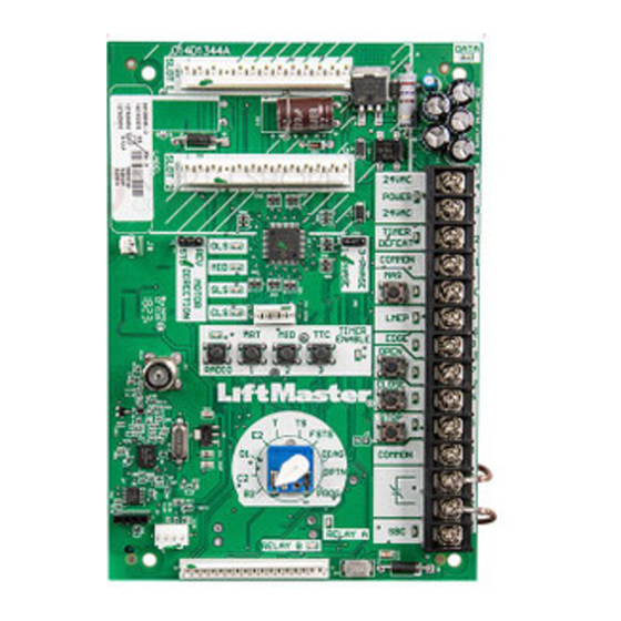
Slots for option boards
Current Sense
(3 Phase Only)
Motor direction
jumper
Coaxial antenna
connecter
System wiring
connector (J3)
REPLACEMENT KIT
To avoid SERIOUS personal INJURY or DEATH from
electrocution, Disconnect electrical power to operator BEFORE
proceeding.
WARNING: This product can expose you to chemicals
including lead, which are known to the State of California to
cause cancer or birth defects or other reproductive harm.
For more information go to www.P65Warnings.ca.gov
INSTALL THE NEW LOGIC BOARD
1. Install the new power board into the operator. Position the
board onto mounting posts pressing fi rmly to ensure posts are
completely through mounting holes.
2. Reconnect all wires:
•
Control Wiring Terminal Block
•
System Wiring Connector (J3)
•
Coaxial antenna
3. Install option boards in slots 1 and/or 2.
4. Set the jumper for motor direction.
5. Make sure the electrical box is clear of all debris and tools.
1
LOGIC BOARD (L5)
K001D8395
Control wiring
terminal block
Advertisement
Table of Contents

Subscribe to Our Youtube Channel
Related Manuals for Chamberlain K001D8395


Summary of Contents for Chamberlain K001D8395
- Page 1 LOGIC BOARD (L5) REPLACEMENT KIT K001D8395 For use in all Logic 5.0 commercial door operators. To avoid SERIOUS personal INJURY or DEATH from INSTALLATION electrocution, Disconnect electrical power to operator BEFORE DO NOT connect the power or activate the operator until instructed proceeding.
- Page 2 INSTALL WIRE HARNESS FOR CURRENT SENSE 3-Phase operators now include Current Sense Technology, which senses high-current conditions and limits operation. The Current NOTE: Black L1 position varies Sense wire provided is REQUIRED for proper operation. by model. If the operator is already equipped with Current Sense, use the existing wire and discard the harness in this kit: BLACK 1.
-
Page 3: Introduction To Programming
PROGRAMMING The following settings need to be programmed for the new logic When power is applied to the operator, the following LED’s will board. illuminate: STOP, CLOSE, OPEN, LMEP, 24Vac, RADIO, DATA, • All remote controls (on board receiver only) TIMER ENABLE, OLS MID, SLS, CLS, and MAS. -
Page 4: Programming Remote Controls
PROGRAMMING REMOTE CONTROLS To prevent possible SEVERE INJURY or DEATH: • Activate door ONLY when it can be seen clearly, is properly • Install a LiftMaster Monitored Entrapment Protection (LMEP) adjusted and there are no obstructions to door travel. device. •... - Page 5 THREE BUTTON REMOTE CONTROL PROGRAMMED FOR OPEN/ REMOTE CONTROL PROGRAMMING FEATURE CLOSE/STOP Program Remote Controls from the 3-button control station NOTE: The following programming requires a LiftMaster Monitored (3BCS). Entrapment Protection (LMEP) device. This feature allows the user to add additional remote controls from Your Security+ 2.0 ®...
-
Page 6: Maintenance Alert System (Mas)
® SETUP (OPTIONAL) To Erase All MyQ Devices: 1. Press and release the RADIO button on the logic board (the For Smartphone App, tablet or PC control, LiftMaster MyQ Internet RADIO LED will light). Gateway (model 828LM) is required. 2. Press and hold the MAS button for 5 seconds. The RADIO LED 1. -
Page 7: Timer-To-Close
TIMER-TO-CLOSE Timer automatically closes door after preset time. All entrapment protection devices must be unobstructed. To prevent possible SEVERE INJURY or DEATH: The operator MUST have at least one LiftMaster Monitored • Install a LiftMaster Monitored Entrapment Protection (LMEP) Entrapment Protection (LMEP) device installed (refer to the device. -
Page 8: Open Mid Stop
OPEN MID STOP The Mid Stop feature is to open the door to a preset point prior to the fully open position. To Program: 1. Close the door. 2. Turn selector dial to PROG. Set to PROG 3. Press and release the MID button on logic board. 4. -
Page 9: Maximum Run Timer (Mrt)
MAXIMUM RUN TIMER (MRT) The operator can learn the time it takes to open or close the door plus and an additional 10 seconds. If the operator does not meet its open or close limit within the set time, it will stop, limiting damage to the door and operator. -
Page 10: Resetting Factory Defaults - Clearing Memory
RESET RESETTING FACTORY DEFAULTS - CLEARING MEMORY To reset most of the user installed settings back to factory defaults: 1. Turn the selector dial to DIAG. 2. Press and hold the STOP button for 5 seconds. The MAS LED will fl ash momentarily when the factory defaults have been Set to DIAG restored. -
Page 11: Installation
NÉCESSAIRE DE REMPLACEMENT DE TABLEAU DE CONTRÔLE (L5) K001D8395 Disponible pour tous les actionneurs de porte commerciaux utilisant le tableau de contrôle Logic 5.0. Pour éviter des blessures personnelles SÉRIEUSES ou la MORT INSTALLATION par électrocution, DÉCONNECTER l’alimentation électrique à... - Page 12 INSTALLATION DU FAISCEAU DE CÂBLES POUR LA DÉTECTION DE COURANT Les actionneurs triphasés sont désormais dotés d’une technologie de détection qui détecte les conditions de haute tension et limite le REMARQUE : Position du L1 black varie selon le modèle. fonctionnement de l’actionneur.
- Page 13 PROGRAMMATION Lorsque l'alimentation est appliquée à l'ouvre-porte, les DEL suivantes s'allument : STOP (arrêt), CLOSE (fermer), OPEN (ouvrir), LMEP, 24 Les confi gurations suivantes doivent être programmées pour la nouvelle Vca, RADIO, DATA (données), TIMER ENABLE (permettre minuterie), carte logique. OLS (inter.
-
Page 14: Programmation Des Télécommandes
PROGRAMMATION DES TÉLÉCOMMANDES Pour empêcher une BLESSURE GRAVE ou une MORT possible : • Activer la porte SEULEMENT lorsqu’elle peut être vue clairement, qu’elle est correctement ajustée et qu’il n’y a aucune • Installer un dispositif de Protection contre le piégeage avec obstruction au déplacement de la porte. - Page 15 TÉLÉCOMMANDE À 3 BOUTONS PROGRAMMÉE POUR FONCTION DE PROGRAMMATION DE LA TÉLÉCOMMANDE L’OUVERTURE/LA FERMETURE/L’ARRÊT Programmation de télécommandes à partir de la station de commande à 3 boutons (3BCS). REMARQUE : La programmation suivante nécessite un dispositif de Protection contre le piégeage avec surveillance LiftMaster (LMEP). Cette fonction permet à...
-
Page 16: Système D'alerte D'entretien (Mas)
® CONFIGURATION MyQ (EN OPTION) Pour supprimer tous les dispositifs MyQ : 1. Pressez et relâchez sur le bouton RADIO de la carte logique (le voyant La passerelle Internet LiftMaster MyQ est exigée (modèle 828LM) pour lumineux DEL RADIO clignotera). l’application pour téléphone intelligent, commande par tablette ou ordinateur. -
Page 17: Minuterie De Fermeture
MINUTERIE DE FERMETURE La fonction mi-course est pour ouvrir la porte à un point prédéterminé avant la position entièrement ouverte. Pour empêcher une BLESSURE GRAVE ou une MORT possible: Au moins un dispositif de Protection contre le piégeage avec surveillance LiftMaster (LMEP) doit être installé... -
Page 18: Ouverture À Mi-Course
OUVERTURE À MI-COURSE La fonction d’arrêt à mi-course ouvrira une porte à une position préétablie avant la position d’ouverture complète. Pour programmer : 1. Fermer la porte. 2. Tourner le cadran de réglage à PROG. Réglé au PROG Set to PROG 3. -
Page 19: Minuterie De Fonctionnement Maximal (Mrt)
MINUTERIE DE FONCTIONNEMENT MAXIMAL (MRT) L’ouvre-porte peut apprendre le temps nécessaire pour ouvrir ou fermer la porte plus ajouter un 10 secondes supplémentaires. Si l’ouvre-porte n’atteint pas la fi n de course ouvert ou fermée dans le temps confi guré, il s’arrêtera, limitant le dommage à... -
Page 20: Restauration Des Valeurs D'usine Par Défaut - Efface- Ment De La Mémoire
RESTAURATION RESTAURATION DES VALEURS D’USINE PAR DÉFAUT - EFFACE- MENT DE LA MÉMOIRE Pour restaurer la plupart des confi gurations installées par l’utilisateur aux valeurs d’usine par défaut : 1. Tourner le cadran de réglage à DIAG. 2. Appuyer et tenir le bouton STOP (arrêt) durant 5 secondes. La DEL MAS clignotera un instant puis les valeurs d’usine par défaut seront Réglé... -
Page 21: Instalación
JUEGO DE REPUESTO DE LA TARJETA LÓGICA (L5) K001D8395 Para todos los operadores de puerta de uso comercial que usan la tarjeta de control Logic 5.0. Para evitar accidentes GRAVES e incluso FATALES por electrocución , desconectar la alimentación eléctrica al operador INSTALACIÓN... - Page 22 INSTALAR EL ARNÉS DEL DETECTOR DE CORRIENTE Los operadores trifásicos incluyen ahora tecnología de detección de corriente para limitar la funcionalidad ante condiciones de sobrecorriente. Es NECESARIO usar el conductor de detección de corriente que se NOTA: Posición de L1 black varía según el modelo.
- Page 23 PROGRAMACIÓN Programar los siguientes parámetros para la nueva tarjeta lógica. Cuando esté conectada la energía del operador, se encenderán los • Todos los controles remotos (únicamente para receptor integrado) siguientes LED: STOP (parada), CLOSE (cerrar), OPEN (abrir), LMEP, 24V DE CA, RADIO, DATA (datos), TIMER ENABLE (temporizador activado), •...
- Page 24 PROGRAMACIÓN DE CONTROLES REMOTOS Para prevenir posibles LESIONES GRAVES o la MUERTE: • Active la puerta ÚNICAMENTE cuando pueda verla claramente, cuando esté correctamente ajustada y no haya obstrucciones • Instale un dispositivo de protección contra atrapamientos en su recorrido. controlado por LiftMaster (LMEP).
- Page 25 CONTROL REMOTO DE TRES BOTONES PROGRAMADO PARA CARACTERÍSTICA DE PROGRAMACIÓN DEL CONTROL REMOTO ABRIR/CERRAR/PARAR Programe los controles remotos desde la estación de control de 3 botones (3BCS, por sus siglas en inglés). NOTA: La siguiente programación requiere un dispositivo de protección contra atrapamientos controlado por LiftMaster (LMEP).
- Page 26 ® PROGRAMACIÓN DE DISPOSITIVOS MyQ (OPCIONAL) Para borrar todos los dispositivos MyQ: 1. Pulse y suelte el botón RADIO en la tarjeta lógica (se encenderá el LED Para usar la aplicación de control con teléfono, tableta o computadora es RADIO). necesario instalar el LiftMaster MyQ Internet Gateway (modelo 828LM).
- Page 27 TEMPORIZADOR DE CIERRE El temporizador cierra automáticamente la puerta después del tiempo programado. No debe haber ninguna obstrucción de los dispositivos de Para prevenir posibles LESIONES GRAVES o la MUERTE: protección. • Instale un dispositivo de protección contra atrapamientos Se debe tener al menos un dispositivo de protección contra atrapamientos controlado por LiftMaster (LMEP).
- Page 28 PARADA DE APERTURA PARCIAL La parada a medio recorrido abrirá la puerta hasta un punto predeterminado antes del punto de apertura total. Para programar: 1. Cierre la puerta. 2. Gire el disco selector a la posición PROG. Gire a PROG Set to PROG 3.
-
Page 29: Mantenimiento
TEMPORIZADOR DE FUNCIONAMIENTO MÁXIMO (MRT) El operador puede programar el tiempo que lleva abrir o cerrar la puerta más 10 segundos adicionales. Si el operador no cumple con su límite de apertura o cierre dentro del límite establecido de tiempo, se detendrá limitando el daño a la puerta y al operador. - Page 30 REAJUSTE DE LAS CONFIGURACIONES REAJUSTE DE LAS CONFIGURACIONES DE FÁBRICA - BORRADO DE LA MEMORIA Para reajustar la mayoría de las confi guraciones instaladas por el usuario nuevamente a las de fábrica: 1. Gire el disco selector a la posición DIAG. Gire a DIAG Set to DIAG 2.
-
Page 31: Notes / Remarques / Notas
NOTES / REMARQUES / NOTAS... - Page 32 © 2016, LiftMaster All Rights Reserved Tous droits réservés 01-39056B Todos los derechos reservados...
Need help?
Do you have a question about the K001D8395 and is the answer not in the manual?
Questions and answers