
Related Manuals for AG-NAV Platinum


Summary of Contents for AG-NAV Platinum
- Page 1 PLATINUM INSTALLATION MANUAL Part No: AAP771- I-J 23-05-2018 Part No: MN-PLATINUM-I-J REV: A AG-NAV 1-800-99 AGNAV...
- Page 2 AG-NAV Inc. AG-NAV Inc. provides this manual “as is”, without warranty of any kind and reserves the right to make improvements and/or changes to the product described in this manual at any time and without notice.
- Page 3 Barrie, ON L4N8Z5, Canada In the event of a problem that cannot be resolved using the information supplied, please contact AG-NAV. You can also gain assistance through the user’s area on our web page at www.agnav.com. For further assistance, contact the AG-NAV technical support line by telephone, fax, or email. AGNAV customer support personnel will discuss your situation, determine the cause of problem and provide the appropriate technical assistance.
- Page 4 MANUAL BEFORE INSTALLATION. A warning placard must be installed before use before releasing the aircraft for operation. The Platinum system is not to be used as a primary source of navigation. See example below. GPS IS FOR DAY VFR FLIGHT ONLY...
-
Page 5: Table Of Contents
Table of Contents 6-10 1. Getting Started………………………………………………….. Getting Familiar with the Platinum System 1.1.1 Platinum console Installation standards / responsibility Reference Documents Component description with weight and location Before Installation Installation Plan Tools required 2. Installing the platinum components…………………………… 10-41 Platinum Installation 2.1.1 Flush mount bracket... -
Page 6: Getting Started
NAV DGPS aerial application guidance system. Before beginning the AG-NAV installation, read the AG-NAV operations manual and become familiar with the modes and functions of operation. The AG-NAV system is designed to meet the precise positioning demands of the material application industry. The AG-NAV system uses the latest DGPS (Satellite Navigation) technology. - Page 7 Platinum console continue…. MAIN CONNECTION AUXILIARY CONNECTION 2 x USB WIFI CONNECTION REDUNDANCY ANTENNA CONNECTION Platinum back panel connections Figure #2 AG-NAV 1-800-99 AGNAV...
-
Page 8: Installation Standards / Responsibility
The aircraft operator is responsible for ensuring that FAA or TRANSPORT CANADA regulations, applying to the installation of the AG-NAV System in the aircraft are followed. Ag-Nav Inc. provides these instructions as a guide to customers and assumes no responsibility or liability for the installation in individual aircraft. - Page 9 Component Description Table 1 below provides the weight and Ag-nav part number of the components. The following table will have the suggested station position to install into the aircraft relative to the airframe datum line. Component Part No. Weight Power consumption...
-
Page 10: Before Installation
Before Installation Before you begin installation, please make sure to carefully read the installation instructions. If any questions arise, please contact Ag-Nav customer support. Contact information is located on page 3 of this manual and on the bottom of each page. -
Page 11: Platinum Installation
Platinum Installation Figure #6 AG-NAV 1-800-99 AGNAV... -
Page 12: Flush Mount Bracket
Platinum installation continues… The Platinum system has Five different mounting options as shown below, the ram mount is optional. The Kit includes the hardware, flush mount, low profile, mounting plate and adjustable mount brackets. MOUNTING KIT HAREWARE RAM MOUNT (Optional) - Page 13 10-32 1/2 stainless steel hardware and then to the aircraft using approved hardware as shown below. Figure #14 PANEL CUTOUT DIMENSIONS Mounting screw assembly Mounting screw sizes for assembly Figure #15 Figure #16 AG-NAV 1-800-99 AGNAV...
- Page 14 Mounting screw rotation for assembly Flush mount assembly for Platinum Figure #17 Figure #18 Mounting flush mount assembly to panel Mounting screws used for assembled to panel Figure #19 Figure # 20 Mounting screw size for assembling flush mount Mounting screws rotation...
-
Page 15: Low Profile Mount Bracket
Other location can be used following FAA or TRANSPORT CANADA regulation. The bracket mounts to the side of the console with 10-32 1/2 stainless steel hardware and then to the aircraft using approved hardware. AG-NAV 1-800-99 AGNAV... - Page 16 Figure #23 AG-NAV 1-800-99 AGNAV...
-
Page 17: Mounting Plate Bracket
Other location can be used following FAA or TRANSPORT CANADA regulation. The bracket mount to the back of the console with 10-32 1/2 stainless steel hardware and then to the aircraft using approved hardware. Figure #24 AG-NAV 1-800-99 AGNAV... -
Page 18: Adjustable Mounting Bracket
The adjustable feature enables the pilot or operator to tilt the console up or down as desired. Other location can be used following FAA or TRANSPORT CANADA regulation. The bracket mount to the back of the console with 10-32 1/2 stainless steel hardware and then to the aircraft using approved hardware. AG-NAV 1-800-99 AGNAV... - Page 19 Figure# 25 AG-NAV 1-800-99 AGNAV...
-
Page 20: Ram Mount Bracket
The ram mount bracket is used to mount the console in similar location as the other brackets, but it offers easy quick movable adjustments and quick disconnect and connect of the console as desired. The Ram mount bolts to AgNav brackets and then to the aircraft using approved hardware as shown below figure #26. AG-NAV 1-800-99 AGNAV... - Page 21 Figure #26 AG-NAV 1-800-99 AGNAV...
-
Page 22: Gps Receiver Installation
The GPS receiver has three led lights located on the front of the panel which provide different indication colors (Red (power), Blue (GPS Signal), Green (Communication)). These led colors should be visible for testing and variation of operation. Use the mounting brackets attached to the unit to mount as shown below (figure #27). AG-NAV 1-800-99 AGNAV... - Page 23 Mounting GPS receiver Figure #30 AG-NAV 1-800-99 AGNAV...
-
Page 24: Guidance Installation
If possible, avoid drilling into the hopper or the hopper stiffeners. Please use the following drawing information and dimensions for the various guidance bar installation. Agnav is not responsible for any installation beyond the installation manual or improper installation. AG-NAV 1-800-99 AGNAV... - Page 25 Internal P210 bright bar dimensions Figure # 33 AG-NAV 1-800-99 AGNAV...
- Page 26 External P207 bright bar dimensions Figure # 34 AG-NAV 1-800-99 AGNAV...
- Page 27 External 889 light bar dimensions Figure # 35 AG-NAV 1-800-99 AGNAV...
- Page 28 Internal 887 light bar dimensions Figure # 36 The guidance unit comes with cables and some with extender cable with connector. See section 2.2.5 for cable connections. AG-NAV 1-800-99 AGNAV...
-
Page 29: Gps Antenna Installation
Vertical Stabilizer. The antenna does not need an external ground plane. See below (figure # 35) for installation information and dimensions. The Antenna should be installed more than 6inchs from any other antennas or receivers’ due to interference. GPS installation dimensions Figure #37 See section 2.5.6 for cable installation. AG-NAV 1-800-99 AGNAV... -
Page 30: Cables And Electrical Connections
Breaker 2.5.1 Install a new 5 Amp circuit breaker for the console (platinum computer) system (12 – 24 V D.C.) power supply in a conventional location. Please Note that this breaker is for the console system only, if have flow system see Flow installation manual for information. -
Page 31: Connecting Remote Switch
The Picture above (Remote Installation) shows an example of the remote switch position, also below (figure #40) shows the remote wiring. AG-NAV 1-800-99 AGNAV... - Page 32 Remote switch Figure #40 AG-NAV 1-800-99 AGNAV...
-
Page 33: Connecting Booms On
2.5.4 Connect the booms on cable to the main computer (platinum console). Position the switch so that when the dump handle is used the switch will turn on and off. If a switch is used to turn the spray on and off, we recommend you remove the switch provided and wire the cable up to another switch to indicate when the spray is on and off. - Page 34 Optional boom Figure # 41 AG-NAV 1-800-99 AGNAV...
-
Page 35: Connecting Indicator Cable
The connectors are labelled to mate with the unit and the harness. Insure the connectors lock well together and cables, connectors are well secured. See platinum main harness external and internal drawings shown in section 2.5.8 Connecting the wiring harness. -
Page 36: Connecting The Wiring Harness
Main pin connector WIFI Connectors Antenna connector Ports Main Harness Cable Main Harness Connection Figure #42 Figure#43 Rotate ring clock wise to tighten. Do not rotate connector housing Main Harness Connection Figure #44 Auxiliary Cable Figure #45 AG-NAV 1-800-99 AGNAV... - Page 37 Platinum main harness external Figure # 46 AG-NAV 1-800-99 AGNAV...
- Page 38 Platinum main harness internal Figure #47 AG-NAV 1-800-99 AGNAV...
-
Page 39: Connecting The Wifi Antenna
Connecting the WIFI antenna Carefully screw on the WIFI connectors to the back of the platinum as shown below. The antennas should be installed away from electronic devices which could disrupted the WIFI signal resulting in a poor WIFI connection to the network. -
Page 40: Dimmer Hub
The USB consist of two ports capable of running two memory sticks. The unit is flush mounted to the aircraft supported with four screws. See drawings (figure #49) below for more detail. Dimmer hub Figure #49 AG-NAV 1-800-99 AGNAV... -
Page 41: Final Installation Checklist
If installing a flow system as well, please see flow install manual regarding cabling and power breaker. If all is checked then the system can be powered. Press the power button on the front of Platinum console (AGNAV symbol). -
Page 42: Setup Testing
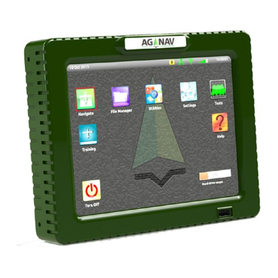
Platinum setup test procedures The installation check list must be completed before starting the setup testing procedure. During this procedure, the platinum test module will be used. This is found on the main page of the platinum shown below (Platinum Main Page). - Page 43 Platinum setup continue….. Communication module Light bar module Figure #52 Figure # 53 Boom switch module Gps receiver module Figure # 54 Figure #55 Flow controller module Gate controller module Figure #56 Figure #57 UFC module Figure #58 AG-NAV 1-800-99 AGNAV...
-
Page 44: Platinum Help Menu
Like any computer maintenance is needed for longevity. Start with keeping the console clean and dry as much as possible. The fines on the back of the platinum act as heat sink (removal of heat) for the processor (heart) of the platinum. -
Page 45: Troubleshooting Guide
No Blue Led check the antenna connection (TNC) Green LED Communication to console No Green LED check the cable connection to the console Please contact Ag-Nav support 24 hours a day 7 day a week for any technical issues. AG-NAV 1-800-99 AGNAV...
Need help?
Do you have a question about the Platinum and is the answer not in the manual?
Questions and answers