Table of Contents
Advertisement
Quick Links
Advertisement
Table of Contents

Subscribe to Our Youtube Channel
Related Manuals for Stealth ST-INV-T10.0


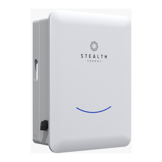
Summary of Contents for Stealth ST-INV-T10.0
- Page 1 VER:1.1 USER MANUAL ST-INV-T10.0 PV grid-connected energy storage inverter...
- Page 2 The contents of the manual and the pictures, logos, symbols, etc. used are owned by Suzhou Stealth Energy Technology Co., Ltd. Persons who are not inside the company are not allowed to publicly reproduce all or part of the content without written authorization.
-
Page 3: Table Of Contents
User Manual User Manual About This Manual Symbol usage In order to ensure the personal and property safety of users when using the 1 Safety instruction product, and to use the product more efficiently and optimally, the manual provides relevant safety information, which is highlighted by the following 1.1 General salfety instruction symbols. -
Page 4: Safety Instruction
User Manual User Manual 1 Safety instruction 5.5.3 Installing the PV Connector 5.6 Battery cable connection Inverter machine is designed and tested in strict accordance with relevant 5.6.1 Requirements on the battery side international safety standards. As electrical and electronic equipment, relevant 5.6.2 Assembling the cable to the Bat connector safety regulations must be observed during its Installation, commissioning, operation and maintenance. -
Page 5: Inverter
Do not open the cover of the inverter when the inverter is working or CE mark. The inverter complies with the requirements of the powered on, otherwise Stealth Energy will not be held responsible. applicable CE guidelines. WARNING TUV certified. -
Page 6: Product Description
2.1Grid-connected PV energy storage system No. Item Description ST-INV-T10.0 is three-phase transformerless string photovoltaic energy storage MonocryStealthine silicon, polycryStealthine silicon, thin- inverters, which are an important part of photovoltaic power generation systems. film batteries that do not need to be grounded. -
Page 7: Dimensions And Weight
Users can view the information 2.2.3 Dimensions and weight of Inverter through the mobile app. For more professional configuration, please contact Stealth after-sales. • Communication interface It can be connected to the WiFi communication data acquisition module to realize... -
Page 8: Working Mode
The above introduction describes the general working of a photovoltaic (PV > Load, PV → Load → Battery → Grid → Battery) system. The operation mode can be adjusted according to the system layout Active Discharge time period :PV will power the loads firstly, on the Stealth Cloud App. The following are the general operating modes of and surplus power will feed-in to the grid. (PV > Load, PV → Load → Grid ) photovoltaic energy storage systems. -
Page 9: Unpacking And Storage
• Unpack and check whether the internal equipment is in good condition. the grid is off. Customers no need to worry about the battery If you find any damage, please contact the shipping company or the after-sales capacity. service of Stealth directly, and provide photos of the damage, so as to provide the Battery min SOC can be set: 10%-100%. Charge battery to min SOC can be set: 10%-100%. fastest and best service. -
Page 10: Delivery List
User Manual User Manual 4 Mechanical Installation 3.3 Delivery list 4.1 Installtion Precautions Before Installing the inverter, make sure the inverter has no electrical connections. Before drilling, make sure to avoid the water and electricity wiring in the wall to avoid danger! !... - Page 11 User Manual User Manual • The Installation wall must have fire resistance, and there must be no flammable • Avoid direct sunlight, rain and snow, and it is best to choose a sheltered substances or flammable gas in the Installation space. installation site, which can prolong the service life of the equipment.
-
Page 12: Installation Tools And Parts
User Manual User Manual 4.3 Installation tools and parts 4.4 Installation of inverter After transporting the inverter to the installation site, install the hanging plate Installation tools include, but are not limited to ,the tools recommended below. on the wall with the expansion bolt assembly, and then hang the inverter on the When necessary, other aids can be used on site. -
Page 13: Electrical Connection
User Manual User Manual 2.Drill holes (about 70mm in depth) and install the hanging plate. 5 Electrical connection Personal protective equipment must be worn when working on electrical wiring. There may be high voltage in the unit! Pay attention to safety before making electrical connections. Exposure of PV strings to sunlight will generate dangerous voltages. -
Page 14: Terminal Introduction
No.of three-phase Power grid impedance Model Remarks parallel machines requirements PV1+ PV2+ Grid Back-up Wifi ST-INV-T10.0 If the number of PV1- / + PV2- METER P parallel connections ST-INV-T8.0 exceeds 8, ≤ 30 < 49mΩ please contact stoll ST-INV-T6.0 technical staff for evaluation. -
Page 15: Ground Connection
5.4 Grid and back-up connection Inverter is connected to the power grid through L (live wire), N (neutral wire) and PV strings ST-INV-T10.0 and have 2 pairs of PV terminals. PE (ground wire). via Back-up_L, Back-up_N and Back-up_GND to connect with important loads. -
Page 16: Assembling The Cable To The Ac&Back-Up Connector
NOTICE Pay attention to the wiring layout of the AC terminals. It is forbidden to connect the phase wires to the PE terminals. Otherwise, the inverter may not operate normally, and the resulting loss has nothing to do with Stealth. -
Page 17: Pv Series Connection
用户手册 5.5.1 PV Input Configuration must be connected together, otherwise Back-Up function will not work. ST-INV-T10.0 and each input has a pair of PV terminals. Two PV inputs, each with 5 电气连接 用户手册 independent MPPT, can be configured in independent mode or parallel mode. -
Page 18: Assembling The Cable To The Pv Connector
筒直到其扣紧。轻拉线缆确保已连 is securely connected. Tighten the 接紧固。使用 2.5~3N·m 的力将密封 ST-INV-T10.0 15000W sealing sleeve and insulating sleeve 套和绝缘套筒紧固。 with a force of 2.5~3N·m. ST-INV-T8.0 12000W Step 4 Check that the polarities of 850V/850V 21.2A/21.2A... -
Page 19: Installing The Pv Connector
888.8 The following table lists recommended DC circuit breaker specifications for different inverters. Model Recommended specifications ST-INV-T10.0 ST-INV-T8.0 NOTICE Before connecting the PV connector to the inverter, check the positive and ST-INV-T6.0 将 PV 连接器连接到逆变器之前,检查电池板的正、负极性,确认无误后才 negative polarities of the solar panel, and then insert the PV connector into the 可将... -
Page 20: Assembling The Cable To The Bat Connector
5 电气连接 用户手册 User Manual User Manual 9 故障排除与维护 用户手册 5.6.2 Assembling the cable to the Bat connector 5.6.3 Installing the Bat Connector 5.6.3 安装 Bat 连接器 The connection of the battery is the same as that of the PV, but a different 5 电气连接... -
Page 21: Type-C Communication Connection
Smart Meter Position Color Smart meters must be authorized by Stealth, any third-party or unauthorized Function Function meters may not be compatible with the Inverter. Stealth will not be liable if the Orange&white meter is not available. Orange Green&white 485_B ST-INV-T10.0 and adopts Acrel's smart meter with CT, which is used to detect the... -
Page 22: Dred Connection
User Manual User Manual Smart Meter LED Indication The DRM communication cable (RJ45) is attached to the inverter ("Connect to Smart Meter LED指示 Peripheral DRED Device" cable), a standard RJ45 cable and plug must be used as 9 故障排除 用户手册 Steady Flashing shown below... -
Page 23: Test Operation
User Manual User Manual 6 Test operation 7 Decommissioning, dismantling, and 9 故障排除与维护 用户手册 discarding Inverter 6.1 Inspection bafore test run Before turning on the inverter for the first time, you need to do the following 7.1 Decommissioning inspections. 8 停运,拆除,废弃一体机 It is not necessary to shut down Inverter under normal circumstances, but 1. -
Page 24: Dismantling
2. If it is not within the allowable range, disconnect the PV+, PV-, Bat, and Grid connections, and restart Inverter; 3. If the fault still exists, please contact the Stealth customer service center. 1. Disconnect PV+, PV-, Bat, Grid, and restart Inverter;... - Page 25 Inverter; 3. If the fault occurs repeatedly, please contact the 3. If the fault still exists, please contact the Stealth Stealth customer service center. customer service center. 1. Disconnect PV+, PV-, Bat, Grid, and restart Inverter;...
-
Page 26: Daily Maintanance
Inverter does not contain maintenance parts, please do not replace the internal components of Inverter without authorization. If any repair service is required, please contact the Stealth Energy Service Center. Otherwise, Stealth Energy will not bear any warranty and joint liability for the resulting losses. - Page 27 User Manual User Manual...
-
Page 28: Quality Assurance
• Any incompatible batteries, loads or other equipment connected to the PV energy storage system. Note: Stealth reserves the right to interpret all content in this user manual. In order to ensure IP65, the inverter must be well sealed, please install the inverter... - Page 29 User Manual Inverter requires regular maintenance, the details are as follows: • Before servicing, ensure that the Inverter is completely isolated from all DC and AC power sources for at least 5 minutes. • Radiator: Please clean the radiator with a clean towel once a year. •...
Need help?
Do you have a question about the ST-INV-T10.0 and is the answer not in the manual?
Questions and answers