Advertisement
Quick Links
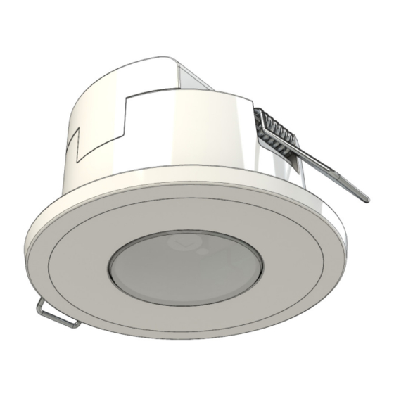
VMOSS/VMOSSB - FLUSH MOUNT 360° CEILING SENSOR
ELECTRICAL SPECIFICATIONS
Supply Voltage Range
Load Rating
Operating Temperature 5°C - 40°C
Wire Size
Wiring
TIMING AND LUX SPECIFICATIONS
Detection Method
Detection Angle
Detection Range
Time Adjustment
Lux Adjustment
Ceiling Cut-Out Size
WARRANTY
This product is covered by the standard 3 year
Vynco Warranty - proof of purchase is required.
Please contact Vynco for details of returns
procedure.
NOTE: This product contains NO user
serviceable parts.
VYNCO.CO.NZ
IP44
230 - 240V AC, 50Hz
2000W Incandescent
400W LED
450W Fluorescent
400W Motor/Fan
1x 2.5mm²
2x 1.5mm²
2.5mm
2
Passive Infrared (PIR)
360°
Ø 6m
5 secs - 30 mins
10 - 2000Lux
Ø 60mm
INSTALLATION INSTRUCTIONS
INSTALLATION
This product should be installed by a suitably
qualified person in accordance with Australian
and New Zealand Wiring rules.
INSTALLATION POSITION
Ideally the sensor should be positioned between
2.4 and 4m above the area to be scanned.
To avoid nuisance tripping,
installation should try to avoid areas:
1.
With water features such as swimming pools
or ponds.
2.
Near heat sources such as air conditioners,
dryers, fire places or heaters.
3.
Which are subject to direct bright
or reflected lights or sunlight.
4.
Which are frequented by animals,
such as pets or birds.
INSTALLATION PROCEDURE
STEP 1
Ensure desired location is suitable and clear of
all obstruction.
STEP 2
Ensure the relevant circuits are isolated and safe.
STEP 3
Cut out a 60mm diameter hole in the ceiling.
STEP 4
Unclip the wiring & terminal cover from the rear
of the sensor.
STEP 5
Connect the supply and load cables to the terminal
block as shown in the wiring diagram.
STEP 6
Replace the wiring & terminal cover.
STEP 7
Fold back installation springs and insert the sensor
into the cut out hole in the ceiling.
STEP 8
Twist the fascia cover off the sensor to access
the controls.
STEP 9
Set and test the controls as described in
the next section.
STEP 10
Replace fascia.
Advertisement

Related Manuals for Vynco VMOSS

Summary of Contents for Vynco VMOSS
- Page 1 INSTALLATION INSTRUCTIONS VMOSS/VMOSSB - FLUSH MOUNT 360° CEILING SENSOR INSTALLATION This product should be installed by a suitably qualified person in accordance with Australian and New Zealand Wiring rules. INSTALLATION POSITION Ideally the sensor should be positioned between 2.4 and 4m above the area to be scanned.
- Page 2 Set lux and duration time to minimum to not operate until its field of detection darkens. STEP 3 Using the VMOSS packaging, cover the sensor completely. Covering the sensor will bypass the surrounding lux sensitivity control and allow the PIR to be activated.
Need help?
Do you have a question about the VMOSS and is the answer not in the manual?
Questions and answers