Advertisement
Quick Links
Integral Product Code
ILBTASE057
Thank you for purchasing an INTEGRAL LED product. When installed correctly this unit will provide years
of service. For support or warranty information please see integral-led.com.
Important Details – Please read prior to installation
Always turn off circuit power at the distribution unit before installation and maintenance. Please ensure
that the power cannot be connected inadvertently.
•
The PIR (passive Infrared) sensor provides automatic control of lighting loads. It is specifically designed to be
mounted onto a batten style luminaire.
•
The detector will detect movement using a PIR sensor and turn the batten on. When an area is no longer
occupied, the batten will switch off after a pre-set time-out period.
•
The detector can switch incandescent, fluorescent, compact fluorescent and LED lighting.
•
A selection of fixing washers are supplied to aid fixing to a variety of battens with an M20 opening.
•
It can be installed to 1-10V enabled dimming and non-dimming luminaires (on/off only).
•
The unit consists of:
• PIR Sensor – detects movement within the detection area to enable control of light switching
•
IR Receiver – receives control and set up commands from the infrared handset
•
Light Level Sensor – measures the light level in the detection area
•
Status LED
• Red flash when valid command is received
• Red flash when movement is detected
•
Range (fig 2.)
Installation (Fig 3.)
1.
For optimal operation:
• Ensure the lens is shielded as much as possible from the light source and adjacent light sources
•
Avoid direct sunlight
• Keep away from heating and ventilation units
2. The product is designed to be mounted to the outside of the luminaire via a 20mm diameter access hole. The
M20 screw thread supplied washers and locking nut will secure the product in place. During installation care
must be taken not to grab the lens when tightening the locking nuts. Do not over tighten and avoid cross
threading or damaging the thread.
3. Ensure that the Silicone washer and/or the IP spacer are used to ensure IP rating.
4.
Notes: Use the 4 spacers where the luminaire housing has a draft angle.
Fixing Kit (Fig 4.)
1.
INCLUDES STANDARD 20MM DIAMETER HOLES AS ADVISED. HOWEVER, SENSOR DOES NOT NECESSARILY
REQUIRE STRAIGHT SIDED HOLES AS SHOWN IN FIGURE 4
2. 5 degree washers are to be used with product walls that have a draft angle. Use of the washers will ensure the
product lies in same horizontal plain as batten. For the ILBTCXXX range of integral products these are not required
INSTALLATION INSTRUCTION
for Integral LED Batten Pir Sensor
3 Year Warranty
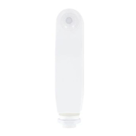
129.6mm
149mm
Dimensions
149 x 36.4 x 28 mm
EN
28mm
Net Wt.
0.13Kg
Advertisement

Related Manuals for Integral LED ILBTASE057

Summary of Contents for Integral LED ILBTASE057
- Page 1 149 x 36.4 x 28 mm 0.13Kg Thank you for purchasing an INTEGRAL LED product. When installed correctly this unit will provide years of service. For support or warranty information please see integral-led.com. Important Details – Please read prior to installation Always turn off circuit power at the distribution unit before installation and maintenance.
- Page 2 Wiring Instructions (Fig 5.) 1. Connections shown are typical for 1-10V dimmable and non-dimmable battens supplied by Integral. 2. **** Supply - Wiring colours should be European Brown live and Blue Neutral must make a note that sensor cabled should be sleeved with the appropriate colour for installation*** 3. The black and white sensor wires should be appropriately sleeved with brown (Live) and blue (neutral) sleeving during installation. Operation using hand controller (Fig 6.) To use the hand controller to program luminaires, point the hand controller at the installed PIR sensor receiver (under the domed PIR sensor lens).
- Page 3 9. Note 1: If the LAMP does not dim from 100% to 20%, either the sensitivity is too high or movement was within 10s. 10. Note 2: Pushing a button at any time, the LED light wall flash once to confirm reception. M (Memory) MODE: 11. Store parameters in the hand controller and PIR sensor. You will first program the hand controller to store the parameters and then transmit them to the PIR sensor unit on the LAMP. 12. EXAMPLE: Set the parameters for: sensitivity 50%, hold time 10seconds, lux , dimming level 20%, dimming time 1mm. Clear the memory: Check whether any parameters are stored: ii. Push the M button once. If parameters have been stored, then the LED will flash once otherwise no parameters are stored Clear the memory: Press the M button for 3 seconds until the LED continually flashes. Check memory was cleared as above in figure a)
- Page 4 LED- LIVE OUT (Red) White NEUTRAL (White/Blue) NEUTRAL (Blue) Do not connect Dim - to LED - or Dim+ to LED+ Integral LED is a division Warranty/Technical and of Integral Memory plc: contact information IP65 are all available at Unit 6, Iron Bridge Close, www.integral-led.com...
Need help?
Do you have a question about the ILBTASE057 and is the answer not in the manual?
Questions and answers