Table of Contents
Advertisement
Quick Links
Advertisement
Table of Contents

Related Manuals for Hobby Components SmartRFy HCMODU0141

Summary of Contents for Hobby Components SmartRFy HCMODU0141
- Page 1 SmartRFy Sensor Module Manual HCMODU0141 Revision 1.1.0...
- Page 2 COPYRIGHT NOTICE This manual, including content and artwork is copyright of Hobby Components Ltd and may not be reproduced without written permission. If you paid for or received a copy of this manual from a source other than Hobby Components Ltd, please contact us at ...
-
Page 3: Table Of Contents
Set the baud rate (BUR=) Set number of transmit resends (TRS=) Set the serial verbose mode (VBM=) Set the modules zone number (ZON=) Set the modules address (ADD=) Turn on/off repeater mode (TRP=) Factory reset (FTRE) © Hobby Components Ltd... - Page 4 Set the test condition for setting the output pin high (SMH=) Set the test condition for setting the output pin low (SML=) Appendix A: Example auxiliary output pin modes Default trigger mode Timer mode Threshold mode © Hobby Components Ltd...
-
Page 5: Smartrfy System Overview
They are addressable and can be grouped into one of 255 zones, with each zone capable of individually addressing 255 devices, giving a total of over 65,000 unique addresses. SmartRFy modules are designed to be both easy and flexible to use by providing three levels of control: Zero configuration (out-of-the-box) © Hobby Components Ltd... - Page 6 For example, a SmartRFy relay module can be reconfigured to control a heating system based on the temperature transmitted from a remote sensor or, turn on a flood light for a set amount of time when triggered by a remote © Hobby Components Ltd...
- Page 7 SmartRFy devices on the network regardless of their zone and address. SmartRFy modules can even be used as a passive wireless serial port for passing non-SmartRFy data to other remotely connected devices. © Hobby Components Ltd...
-
Page 8: Smartrfy Sensor Module
(see SKU: HCMODU0003). By default the sensor module will transmit the state of a connected PIR whenever its state changes. This transmitted state may then be used by any suitably configured remote SmartRFy module capable of receiving its data. © Hobby Components Ltd... -
Page 9: Features
● Can automatically transmit state changes from a connected PIR sensor. ● Auxiliary digital output can be programmed to automatically trigger based on readings from any of the connected sensors and supports on/off, toggle, and timer modes. © Hobby Components Ltd... -
Page 10: Specification
Open collector with 10K pullup. 100mA max sink current Interfaces: RF Tx, serial UART, PIR, and relay Aux digital output Module dimensions (WxDxH): 44.2 x 36.6 x 20mm All measurements taken at Vdd=5V, 25 o © Hobby Components Ltd... -
Page 11: Sensor Module Features
This sample rate can be changed via the serial interface using the temperature (TTT) and humidity (HTT) transmit rate commands and can be set anywhere between 10 and 65535 seconds. Setting either transmit rate to 0 will disable reading and transmitting of that measurement. © Hobby Components Ltd... -
Page 12: Pir
Note: There is no pull-up resistor on the S input pin and so it will float between a logic high and low when disconnected from the sensor. Therefore it is recommended to connect this pin to 5V using the supplied jumper when a PIR sensor is not connected. © Hobby Components Ltd... -
Page 13: Ldr
It consists of an open-collector output with a 10K pullup resistor and is capable of sinking up to 100mA of current. © Hobby Components Ltd... -
Page 14: Leds
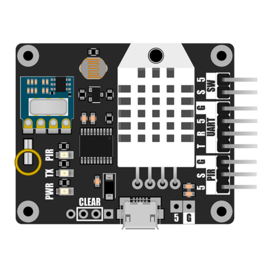
The sensor module includes a set of 3 LEDs which indicate the current state of the module. PWR LED (green) Indicates the module is currently powered. TX LED (red) Indicates the module is currently transmitting. PIR LED (amber) Indicates a connected PIR sensor is currently triggered (S = high). © Hobby Components Ltd... -
Page 15: Serial Uart
Note that when receiving passive serial data from a remote SmartRFy device, the modules receive serial buffer is limited to 25 bytes and the maximum data transfer rate from a remote device is limited by the RF transfer rate and not the actual serial port connection speed. © Hobby Components Ltd... -
Page 16: Default Configuration Settings
Note: Connecting the module to a PC via its serial port will require an additional USB to serial adapter (see Hobby Components items HCARDU0011 or HCMODU0076). Clear (Factory Reset) The module is capable of storing a number of user configuration settings in its non-volatile memory. -
Page 17: Smartrfy Commands
All responses are terminated with a carriage return and line feed. ● No serial data sent to the local device, command or otherwise, may exceed 25 characters in length (including carriage return / linefeed termination). © Hobby Components Ltd... -
Page 18: Local Command Format
Local command format Example: S etting and confirming the zone of the local device *ZON=1<CR><LF> Sets the zone of the connected module to 1. Response: OK<CR><LF> *ZON?<CR><LF> Requests the current zone of the local device. Response: 1<CR><LF> © Hobby Components Ltd... -
Page 19: Smartrfy Generic Commands - Quick Lookup Table
State: Repeater state (0 = off, 1 = on) Note: Turns on or off repeater mode TRP=State Only available on modules with both RF Tx (default: off) & Rx capability Performs a factory reset – all FTRE settings a restored to their default None values © Hobby Components Ltd... -
Page 20: Sensor Module Specific Commands - Quick Lookup Table
65525). Default = 0 (disabled). low when time has elapsed Sets the threshold value required to Threshold: A decimal number which sets the level STH=Threshold pull the output pin SW0 high (default: required to trigger the output pin © Hobby Components Ltd... -
Page 21: Generic Smartrfy Commands
Note that all commands must be proceeded with a carriage return and line feed, but for clarity purposes this is omitted from the examples in this section. Firmware version (FWV?) Gets the firmware version of the module. Example: *FWV? Returns: Vx.x (C) HobbyComponents.com Where Vx.x is the version number © Hobby Components Ltd... -
Page 22: Get The Modules Zone (Zon?)
Returns: OK Set the baud rate (BUR=) Sets the communication baud rate for the serial UART interface. There are 8 (0 to 7) possible settings for the baud rate: 0 = 1200 BAUD 1 = 2400 BAUD © Hobby Components Ltd... -
Page 23: Set Number Of Transmit Resends (Trs=)
The number of resends can be set from 0 (no resends) to 5. Default: Example: *TRS=3 The above example will set the number of resends to 3. Therefore any data wirelessly transmitted by the module will be transmitted a total of 4 times. Returns: OK © Hobby Components Ltd... -
Page 24: Set The Serial Verbose Mode (Vbm=)
255 all modules within range will respond to the data as if it is in the same zone as itself. Therefore this zone number can also be used when you require the module to control multiple remote modules in different zones. Default: © Hobby Components Ltd... -
Page 25: Set The Modules Address (Add=)
Setting the repeater mode to 1 will turn on repeater mode and setting it to 0 will turn it off. Note: Turning on the repeater mode will double network traffic for any modules within range. © Hobby Components Ltd... -
Page 26: Factory Reset (Ftre)
Returns: OK Factory reset (FTRE) Performs a factory reset of the module. All module settings will be restored to their factory defaults. Example: *FTRE The above example will restore all settings to their defaults. Returns: OK © Hobby Components Ltd... -
Page 27: Smartrfy Sensor Module Commands
10 and 65535 seconds. Setting the transmit time to 0 will disable automatic reading and transmitting of humidity measurements. Default: (1 minute) Example: *HTT=600 The module will now automatically read and transmit the current humidity every 600 seconds (10 minutes). Returns: OK © Hobby Components Ltd... -
Page 28: Humidity Transmit Name (Htn=)
DHT22 sensor. The transmit time can be set anywhere between 10 and 65535 seconds. Setting the transmit time to 0 will disable automatic reading and transmitting of temperature measurements. Default: (1 minute) © Hobby Components Ltd... -
Page 29: Temperature Transmit Name (Ttn=)
10 and 65535 seconds. Setting the transmit time to 0 will disable automatic reading and transmitting of LDR measurements. Default: (1 minute) Example: *LTT=600 The module will now automatically read and transmit the current light level every 600 seconds (10 minutes). Returns: OK © Hobby Components Ltd... -
Page 30: Ldr Transmit Name (Ltn=)
Sets the state of the module's auxiliary digital output pin. The command can be used to pull high (5V) or pull low (0V) the on-board digital output pin. SW0=0 ( off) / SW0=1 ( on) Default: © Hobby Components Ltd... -
Page 31: Set An Alternative Name For The Digital Output Pin (Swn=)
Setting the pin high time to anything between 1 and 65535 will cause the pin to stay high until that amount of time (in seconds) has passed. Default: 0 (disabled) © Hobby Components Ltd... -
Page 32: Set The Threshold Value To Set The Output Pin High (Sth=)
SW0 command and together with the pin low mode (SML) determine if the pin should be pulled low. (Also see pin commands SWO, STH, STL, SMH, SML, and Appendix A for more options and examples of configuring the output pins). Default: © Hobby Components Ltd... -
Page 33: Set The Test Condition For Setting The Output Pin High (Smh=)
Default: Example: *SMH=> In the above example the output pin will be pulled high if the module receives the pin command SW0 with a value greater than the current pin threshold high (STH) level. Returns: OK © Hobby Components Ltd... -
Page 34: Set The Test Condition For Setting The Output Pin Low (Sml=)
Default: Example: *SML=< In the above example the output pin will be pulled low if the module receives the pin command SW0 with a value less than the current pin threshold low (STL) level. Returns: OK © Hobby Components Ltd... -
Page 35: Appendix A: Example Auxiliary Output Pin Modes
PIR header of the sensor module and will be used to control a light bulb (via a relay module). Change the following settings via the modules serial interface (see serial uart section for information about interfacing to the modules serial interface): © Hobby Components Ltd... -
Page 36: Timer Mode
Threshold mode In threshold mode the output pin can be programmed to automatically pull high or low when a value from one of the sensor modules sensors goes above or below a predefined pair of thresholds. © Hobby Components Ltd... - Page 37 Threshold high = 22.5 (default) *STL=25 Threshold low = 25 (default) *SMH=< Threshold high mode = trigger value must be less than STH (default) *SML=> Threshold low mode = trigger value must be greater than STL (default) © Hobby Components Ltd...
- Page 38 Dimensions © Hobby Components Ltd...
- Page 39 HOBBYCOMPONENTS.COM FORUM.HOBBYCOMPONENTS.COM BLOG.HOBBYCOMPONENTS.COM © Hobby Components Ltd...
Need help?
Do you have a question about the SmartRFy HCMODU0141 and is the answer not in the manual?
Questions and answers