Table of Contents
Advertisement
Quick Links
Advertisement
Table of Contents

Related Manuals for Hobby Components SmartLCD

Summary of Contents for Hobby Components SmartLCD
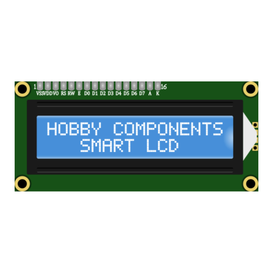
- Page 1 SmartLCD Backpack Module for 1602 & 2004 LCD Displays HCMODU0162 Revision 1.1.0...
- Page 2 ( w ww.hobbycomponents.com ) . COPYRIGHT NOTICE This manual, including content and artwork is copyright of Hobby Components Ltd and may not be reproduced without written permission. If you paid for or received a copy of this manual from a source other than Hobby Components Ltd, please contact us at ...
-
Page 3: Table Of Contents
I2C Mode Specification General Operating Conditions Attaching the SmartLCD to a display Interface Clear (Factory Reset) Setting the SmartLCD to 16x2 or 20x4 character mode Mode (UART Terminal/AT mode) External 5V Power I2C Interface Serial UART Interface Terminal mode AT command mode... - Page 4 Set I2C address (0x0D) Contrast (0x0E) Display Software Version (0x0F) Clear Error State (0xFB) I2C Status Register I2C ADC Register Serial UART – AT Command Mode AT+PR=String AT+CLR AT+RC=Row,Col AT+DS=State AT+DC=State AT+DB=State AT+BL=Level AT+PC=Index AT+SC=Index,Row0,Row1,Row2,Row3,Row4,Row5,Row6,Row7 AT+CD=Direction AT+BR=Baud AT+TO=Time AT+INI AT+BT? AT+BP? AT+BCL AT+AD?
-
Page 5: Description
UART interface (9600 default BAUD rate) to the SmartLCDs UART header and the SmartLCD will automatically output any ASCII printable text it receives to the LCD. As well as printable text the SmartLCD also supports several ASCII control codes such as line feed, carriage return, backspace, delete etc. -
Page 6: I2C Mode
(SmartLCD) and example sketches to make controlling the SmartLCD module from your own sketches as simple as possible. The library will give full control of the SmartLCD using a set of straightforward library commands. The SmartLCD library can be downloaded from the software section of our support forum here: https://forum.hobbycomponents.com/viewtopic.php?f=58&t=2206... -
Page 7: Specification
Specification Model number: HCMODU0162 Supply voltage: Display type: Supports 16 x 2 or 20 x 4 alphanumeric HD44780 LCDs Supply current: 9.8mA Interfaces: I2C, serial UART and external keypad Module dimensions: 42mm x 23.5mm General Operating Conditions Parameter Symbol Condition Unit Supply voltage Vdd-Vss... -
Page 8: Attaching The Smartlcd To A Display
Note that the SmartLCD module is only compatible with 16 character by 2 line and 20 character by 4 line alphanumeric LCD displays using a Hitichi HD44780 (or HD44780 compatible) controller. - Page 9 Note: By default the SmartLCD is configured for a 16 character by 2 line display. If you have fitted the SmartLCD to a 20 character by line display you will need to initialise the display to 20x4 display mode to take advantage of the 20x2 LCDs additional character resolution.
-
Page 10: Interface
Clear (Factory Reset) The SmartLCD is capable of storing a number of user configuration settings in the non-volatile memory. This allows the module to retain these settings even after power is removed. The two pads marked ‘CLEAR’ provide a means of restoring the module back to its factory default settings. -
Page 11: Setting The Smartlcd To 16X2 Or 20X4 Character Mode
20x4 display modes. By default the SmartLCD will be initialised into 16x2 mode when a factory reset is made. If you have fitted the SmartLCD to a 20x4 display the SmartLCD can be set to 20x4 mode by connecting the ‘C’ pin on the SmartLCDs I2C interface header to any GND pin whilst... -
Page 12: Mode (Uart Terminal/At Mode)
External 5V Power Besides powering the SmartLCD module from any of the interface headers, the module can also be powered via a GND (0V) and 5V connection to solder pads marked ‘G’ and ‘5V’. This provides a convenient way to power the module from an external 5V power source. -
Page 13: Serial Uart Interface
Passive mode can be selected by connecting the supplied jumper across both MODE header pins. In this mode the SmartLCD will automatically display any printable ASCII text received via its UART Rx pin. This allows the module to be used as a simple terminal display. -
Page 14: At Command Mode
In AT command mode full access to the SmartLCD's features is available by simple AT text based commands. This includes outputting text and control of the screen, plus full access to the SmartLCD's features. For a list of available AT commands and how to use them please see the software section of this manual. -
Page 15: Software
Master to slave write format When writing to the SmartLCD from an I2C master, the format of the data consists of a 7 bit address byte (plus 1 R/W bit), a command byte. Following the command byte there may be one or more parameter bytes depending on the type of command sent in the command byte. -
Page 16: I2C Commands
I2C commands Command Code (hex) Parameter Number Parameter Param Min Param Max Print character 0x00 ASCII code for character to be printed 0x20 0x7E Clear screen 0x01 Row index 0x00 0x03 Set cursor position 0x02 Column index 0x00 0x4F Display state 0x03 0x00 (LCD OFF) or 0x01 (LCD ON) 0x00... -
Page 17: Print Character (0X00)
Table2: I2C command lookup table Print character (0x00) Writes a single printable ASCII character to the screen at the current cursor position. Once the character is printed the cursor is then automatically moved to the next character position. Parameter(s): The command has one parameter which specifies the ASCII character code to print. Printable characters range between 0x20 (‘... -
Page 18: Display State (0X03)
Parameter(s): There are two parameters, the first sets the cursor row position. Note that on a 16 x 2 line display only rows 0 to 1 are visible. The second parameter sets the cursors column position. Note that on a 16 x 2 line display only columns 0 to 15 are visible. -
Page 19: Backlight State (0X06)
Enables or disables blinking of the cursor. Parameter(s): The command has one parameter which specifies the blink state. A value of 0 will disable blinking, and a value of 1 will enable cursor blinking. Backlight State (0x06) Sets the brightness of the backlight. Parameter(s): The command has one parameter which specifies the brightness of the backlight in 10% increments where 0 = backlight off and a value of 10 = 100% on. -
Page 20: Cursor Direction (0X09)
Writes a user defined 5 x 8 pixel bitmap to one of the eight custom characters. Note that on 16x02 and 20x04 displays the eighth character row is not visible. After writing to one of the custom characters it is necessary to reset the cursor position before any further characters can be written to the screen. -
Page 21: Initialise The Display (0X0A)
Play Note (0x0C) Plays one of 12 musical notes for a specified duration. Note that this command requires the optional keypad and speaker accessory to be connected to the SmartLCD. Parameter(s): This command has two parameters, the first selects the note to play. See table below for a list of available notes. -
Page 22: Set I2C Address (0X0D)
1 = 10 milliseconds and a maximum value of 0xFF = 2.55 seconds. Set I2C address (0x0D) Changes the I2C slave address for the SmartLCD. Once this command is issued the display will immediately respond to commands sent to the new slave address and will no longer respond to the original address. -
Page 23: Contrast (0X0E)
The command has one parameter that specifies the contrast level. A value of 0 = maximum contrast and a value of 0xFF = minimum contrast. Display Software Version (0x0F) Shows the version of firmware flashed into the SmartLCD by displaying it to the LCD. Parameter(s): None Clear Error State (0xFB) Clears the error flag in the status register. -
Page 24: I2C Status Register
The contents of the status register can be obtained by performing a single byte read from an I2C master device. Bit 7 BUSY: SmartLCD busy status 0: SmartLCD is ready to accept new commands. 1: SmartLCD is busy executing the last command. Bit 6 STATUS: SmartLCD error status 0: Last command executed without error. -
Page 25: I2C Adc Register
The smart LCD includes an 8-bit ADC which can be accessed via the A pin on the keypad header. When the external SmartLCD keypad is connected it is used for sensing the state of the keypad buttons. However, if the external keypad is not connected this pin can be used as a general purpose 8-bit ADC. -
Page 26: Serial Uart - At Command Mode
2.55 seconds) AT+CT=Level Contrast level Level: Contrast level (0 = max, 255 = min) AT+FV? Get software version None Software version * Requires optional SmartLCD keypad to be connected Page 2 6 Smart LCD Backpack Module Manual | ©Hobbycomponents.com ... -
Page 27: At+Pr=String
SmartLCD is available, including printing text to the screen and reading of the status and ADC registers. The following is a list of available AT commands: Can be used to test the connection to the SmartLCD. Sending the ASCII text AT will cause the Smart LCD to respond with an ‘OK’... -
Page 28: At+Rc=Row,Col
AT+RC= R ow , C ol Sets the row and column position of the cursor where row 0, column 0 is the top left character position of the screen. There are two parameters, the first sets the cursor row position. Note that on a 16 x 2 line display only rows 0 to 1 are visible. -
Page 29: At+Db=State
AT+DB= S tate Enables or disables blinking of the cursor. The command has one parameter which specifies the blink state. A value of OFF will disable cursor blinking, and a value of ON will enable cursor blinking. Example: AT+DB=ON Turns cursor blinking on Response: OK AT+BL=... -
Page 30: At+Sc=Index,Row0,Row1,Row2,Row3,Row4,Row5,Row6,Row7
AT+SC= I ndex,Row0,Row1,Row2,Row3,Row4,Row5,Row6,Row7 Writes a user defined 5 x 8 pixel bitmap to one of the 8 custom characters. Note that on 16x02 and 20x04 displays the eighth character row is not visible. After writing to one of the custom characters it is necessary to reset the cursor position before any further characters can be written to the screen. -
Page 31: At+Br=Baud
Response: OK AT+TO= T ime Sets the serial communications timeout time if communication with the SmartLCD is interrupted or an error occurs. Note: default timeout time is 2 seconds, any new value set will be stored in the Smart LCD's non-volatile memory. -
Page 32: At+Ini
Response: OK AT+BT? Gets the SmartLCD button number for the last button to be pressed. If no button has been pressed since the SmartLCD was powered or an AT+BCL command was sent then the command will return an index value of 0. -
Page 33: At+Bp
AT+BP? Checks if any of the SmartLCD keypad buttons are currently being pressed. Example: AT+BP? Gets the current button pressed status Response: F = No buttons are currently pressed on the external keypad. T = A button on the external keypad is being pressed. -
Page 34: At+Be=Note,Time
AT+BE= N ote , T ime Plays one of 12 musical notes for a specified duration. Note that this command requires the optional SmartLCD keypad and speaker accessory to be connected to the SmartLCD. This command has two parameters: Note ... -
Page 35: At+Ct=Level
Sets the contrast level of the screen. The command has one parameter that specifies the contrast level. A value of 0 = maximum contrast and a value of 255 = minimum contrast. The SmartLCD ships with a default contrast level of 55... -
Page 36: Serial Uart - Passive Mode
SmartLCD into passive mode simply connect the supplied jumper across the Mode header pins. When in passive mode the SmartLCD will respond to ASCII data sent to it with a baud rate of 9600bps, 8 data bits, 1 stop bit and no parity. -
Page 37: Optional Features - Lcd Keypad
Optional Features - LCD Keypad The SmartLCD's features can be further expanded with the addition of the SmartLCD keypad (see item SKU: HCKITS0058). This add-on board connects to the Smart LCD's keypad header using a single 4 way cable. Once connected it adds the additional features of keypad control (up, down, left, right, select, and back) and audible output to your end application. -
Page 38: Optional Features - Wireless Access
Bluetooth master module to the microcontrollers serial interface. Once a wireless connection is established, AT commands can be sent to the SmartLCD when in serial AT mode, or ASCII text when in serial passive mode, just as if the SmartLCD was connected directly to the microcontroller. - Page 39 FOR NEW PRODUCT ANNOUNCEMENTS AND OFFERS: LIKE US ON FACEBOOK: /HOBBYCOMPONENTSLTD AND FOLLOW US ON TWITTER: /HOBBYCOMPONENTS Page 3 9 Smart LCD Backpack Module Manual | ©Hobbycomponents.com ...
- Page 40 WWW.HOBBYCOMPONENTS.COM FORUM.HOBBYCOMPONENTS.COM BLOG.HOBBYCOMPONENTS.COM Page 4 0 Smart LCD Backpack Module Manual | ©Hobbycomponents.com ...
Need help?
Do you have a question about the SmartLCD and is the answer not in the manual?
Questions and answers