Advertisement
Quick Reference Guide
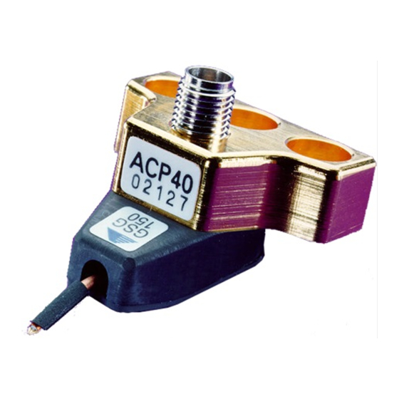
ACP40-GSG-xxx Probes
The ACP40-GSG-xxx probe features include:
• Standard Pitch: 100, 125, 150, 200 and 250μm
• 40 GHz Ground-Signal-Ground footprint microwave probe with Air Coplanar tip and 2.92mm
(K™ compatible) precision coaxial connector
XXX defines the pitch (center-to-center spacing between adjacent probe fingers).
Your calibration kit coefficient definitions are found on the inside of the probe box lid.
C
!
Use care when installing or handling the probe. Do not touch, bump or snag the probe tip.
Do not bend or flex the microwave absorber.
Probe Handling/Installation
Before mounting, inspect the probe for signs of dirt or visible wear. Use a
positioner with a standard 3-pin microwave mount. Use the middle (guide)
pin to align the probe and two mounting screws to snug-tighten the probe
(use 9/64 Contact Substrate (PN 005-018) to planarize the probe using the
positioner planarization adjustment.
Use high-performance microwave cable with 2.92mm (K™ compatible)
connectors.
When connecting RF connectors, carefully mate the connectors and tighten them by rotating only the male connector nut.
Use an 8 in-lb calibrated torque wrench to tighten the connectors.
Use the positioner cable clamp to relieve cable strain on the probe. Do not overtighten the clamp.
When unused, always cover the probe precision connector with the plastic cap supplied with the probe.
Probe Viewing
Always observe the probe tips when making the contact with the DUT. With the microscope focused
on the DUT and the probe tips safely raised, the probe tips appear out of focus.
Use the x- and y-axis knobs to position the probe tip above the DUT contacts. Use the z-axis knob to
bring the probe tips down to the device.
Before making contact, make sure that the probe station chuck is in the contact position and that the
platen arm is fully down.
When contacting a device, watch the probe tips through the microscope. Do not use electrical
readout as a substitute for microscope viewing. Observe contact and skating, then look for electrical readout.
Positioner Arm Planarization
The probe tip itself is planarized with high precision. However, it may still be
necessary to planarize the positioner arm to conform the probe tip plane to the
plane of the device being probed.
PN 153-231-B
AUTION
www.formfactor.com
Cable clamp
Positioner arm planarization
adjustment knob
ACP40-GSG-xxx Probes • 1
Advertisement
Table of Contents

Related Manuals for FormFactor ACP40-GSG Series

Summary of Contents for FormFactor ACP40-GSG Series
- Page 1 The probe tip itself is planarized with high precision. However, it may still be adjustment knob necessary to planarize the positioner arm to conform the probe tip plane to the plane of the device being probed. PN 153-231-B www.formfactor.com ACP40-GSG-xxx Probes • 1...
- Page 2 Contact substrate Probe Verification To verify the performance of the probe, you can use the Probe Test feature of FormFactor's WinCal software. An active cable calibration in the VNA and measurements of ISS Short, Open and Load standards are used to provide insertion and return loss for the probe.
- Page 3 To achieve best measurement accuracy when doing microwave on-wafer measurements above 10-15 GHz, use LRRM calibration routine with automatic load inductance determination as implemented in FormFactor WinCal software. If you choose to do SOLT calibration, Calibration Kit Definitions for your probes are found on the inside of the probe box lid.
- Page 4 © Copyright 2018 FormFactor, Inc. All rights reserved. No part of this document may be reproduced, transmitted or displayed in any form or by any means except as duly authorized by FormFactor, Inc. FormFactor and the FormFactor logo are trademarks of FormFactor, Inc. All other trademarks are the property of their respective owners.
Need help?
Do you have a question about the ACP40-GSG Series and is the answer not in the manual?
Questions and answers