Table of Contents
Advertisement
Advertisement
Table of Contents

Related Manuals for ONEFINITY QCW Frame


Summary of Contents for ONEFINITY QCW Frame
- Page 1 Installation and Operation Instructions QCW (Quick Change Wasteboard) Frame...
-
Page 2: Table Of Contents
Contents General Notes Safety Rules Description Anatomy of the QCW Frame Specifications (Woodworker Version) Specifications (Journeyman Version) Assembly Instructions 14-25 Spindle/Router Installation Wasteboard Creation Wasteboard Installation: Secure from Beneath 28-32 Wasteboard Installation: Secure from Above 33-36 Onefinity Warranty Policy 37-38... -
Page 3: General Notes
General Notes This manual serves to familiarize you with your Onefinity CNC machine and provide all neces- sary information required to operate the machine safely and professionally. This manual is applicable for the Onefinity Woodworker and Onefinity Machinist, hereafter referred to as Onefinity. -
Page 4: Safety Rules
Safety Rules General Instructions: These operating instructions explain the Onefinity and the correct handling of the CNC sys- tem. Please read these operating instructions and accompanying documents in their entirety before commissioning of the system in order to become familiar with the characteristics and the operation of the product. - Page 5 Protective Measures: The Onefinity has been constructed for advanced users and is only to be operated by techni- cally skilled persons above the age of 16. The CNC gantry milling system as well as associated tools, small parts and electrical components are to be stored outside the reach of children.
- Page 6 Safety Rules Use of the Power Tool: Caution: Do not alter or misuse the tool. Any alteration or modification is a misuse and may result in serious personal injury. Caution: Disconnect the plug from the power source before you make any adjust- ments, change accessories, or store the tool.
- Page 7 Safety Rules Care of the Power Tool: NOTICE: Maintain the tools. Check for misalignment or binding of moving parts, breakage of parts and any other conditions that may affect the power tool's operation. If damaged, have the power tool repaired before use. Many accidents are caused by poorly maintained power tools.
- Page 8 Safety Rules Emergency Stop Switch : The emergency stop is located on the top of the Controller housing. In order to be able to inter- vene at all times, the emergency stop has to be positioned in a suitable place. By pressing the emergency stop switch, the emergency stop is triggered.
- Page 9 Workspace: The workspace needs to provide enough space around the Onefinity CNC for the machine to work comfortably and to be able to fully use its traveling paths. Additionally, a safe distance to possibly nearby positioned machines is to be maintained. The location of the machine as well as the workplace surrounding the machine has to be sufficiently illuminated.
-
Page 10: Description
The machine table may consist of any solid flat surface big enough to mount the Rails and Controller. The Onefinity consists of the following, sometimes optional, components: - Onefinity Woodworker, Machinist; - electronic control... -
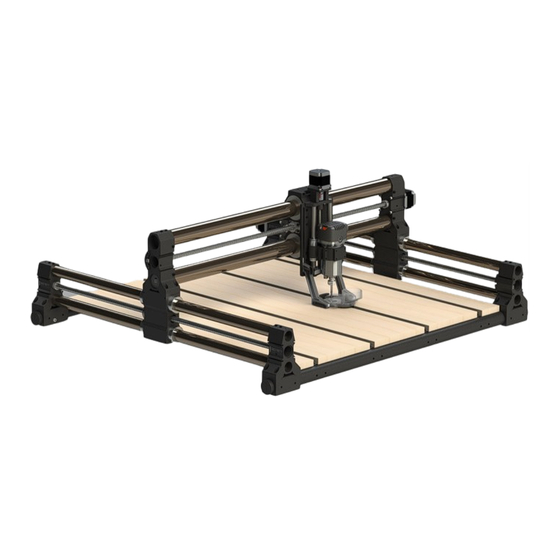
Page 11: Anatomy Of The Qcw Frame
Anatomy of the QCW Frame QCW Frame Wasteboard QCW Frame End QCW Frame T-Track Extrusion QCW Frame Tube... -
Page 12: Specifications (Woodworker Version)
General Disclaimer: While Onefinity has made every effort at the time of publication to ensure the accuracy of the information provided herein, product specifications, configurations, system/component/options availability are all subject to change without notice. Product design specifications and colours are subject to change without notice and may vary from those shown. Errors and omissions excepted. Images displayed... -
Page 13: Specifications (Journeyman Version)
General Disclaimer: While Onefinity has made every effort at the time of publication to ensure the accuracy of the information provided herein, product specifications, configurations, system/component/options availability are all subject to change without notice. Product design specifications and colours are subject to change without notice and may vary from those shown. Errors and omissions excepted. Images displayed... - Page 14 Onefinity machine. Step 1: Set the QCW Frame Tube Assemblies (Red Arrows) on a bench or solid surface and place them close to where you would like them to be installed. Fasten the first T-Track Extru- sion (Blue Arrow) to the first QCW Frame Tube Assembly (Red Arrow) using the QCW Frame Assembly Bolts (Green Arrow).
-
Page 15: Assembly Instructions
Note: It is highly recommended that you view all of our assembly videos prior to attempting to assemble your Onefinity machine. Step 1: Set Y-Rails (Red Arrows) on the QCW Frame Ends as shown below. Note: If you have a “Secure from Beneath” version, please go to section “Wasteboard Creation and Installa-... - Page 16 Assembly Instructions Step 3: Place the X-Rail (Green Arrow) on the Y-Rails Gantry Blocks (Blue Arrows) Step 4: Adjust Y-Rails (Red Arrows) until the Gantry Assemblies (Green Arrows) are flush with X-Rail Ends (Blue Arrows). Note: It is important that these parts are flush with each other before fastening together.
- Page 17 Assembly Instructions Step 5: Once you have ensured the Y-Axis Gantry Blocks and X-Axis Rails Ends are flush, fasten the front of the X-Rail to the Y-Axis using four (4) X-Rail Mounting Screws (Blue Arrows) Step 6: Fasten the back of the X-Rail to the Y-Axis using the remaining four (4) X-Rail Mount- ing Screws (Green Arrows)
- Page 18 Assembly Instructions Step 7: Fasten the front of the Y-Rails to your QCW Frame using only one (1) Y-Rail Mounting Screw per side (Green Arrow). You will use the remaining screws later. Step 8: Place the Controller beside the machine as shown below.
- Page 19 Assembly Instructions Step 9: Using the Display Mounting Hardware, mount the Display Mount to the front of the Rail End closest to the Controller. Step 10: Attach Display to Display Mount.
- Page 20 Assembly Instructions (Wiring) Step 11: It’s now time to wire up your machine. We’ll start with the Y-Axis’s. Plug connector labelled M1 into the controller port labelled M1 (Green Arrow). Plug connector labelled Y1 into the front of the right Y-Rail (Green Arrow). Plug connector labelled M2 into the controller port labelled M2 (Red Arrow).
- Page 21 Assembly Instructions Step 12: It’s now time to power up your machine. Start by twisting the Emergency Stop But- ton clockwise to release it to the “ON” position (Green Arrow). Next make sure your display is plugged into the Controller and a wall outlet and turn on the Touch Display by pushing the ON button (Red Arrow).
- Page 22 Assembly Instructions Step 14: Now Jog the Y-Axis until the X-Rail is all the way to the back of the machine. Do this by tapping the Y+ jog button (Red Arrow). Tap the Y+ button 8 times. Once you have finished jogging, your Y position should read 800mm (Yellow Arrow) Step 15: After jogging, your machine should look like the picture below.
- Page 23 Step 16: After moving the X-Axis all the way to the back, fasten the back of the Y-Rails to your QCW Frame using only one (1) Y-Rail Mounting Screw per side (Green Arrow). Step 17: We will now jog the Y-Axis to bring the X-Rail back to the front of the machine.
- Page 24 Step 18: With the X-Rail all the way to the front again, finish fastening the Y-Rails to the QCW Frame using another three (3) Y-Rail Mounting screws per side (Green Arrow). Step 19: Repeat steps 14 and 15 to jog the Y-Axis until the X-Rail is to the back of the machine again.
- Page 25 Stiffy Block to attached the Z-Slider. Step 21: Square the Z-Slider to your table then tighten the Z-Slider Mounting Screws. Next, plug the Z-Sliders stepper motor into the Curly Cable. Congratulations, you have finished assembling your new Onefinity CNC Machine!
-
Page 26: Spindle/Router Installation
Spindle/Router Installation Step 1: Manually lower the Spindle Mount until it’s roughly 1/4” from bottoming out. Do this by rotating the Stepper Motor Coupler (Green Arrow). Insert the Router (Blue Arrow) into the Spindle Mount (Red Arrow) Step 2: Slide the Router all the way down in the Spindle Mount. Tighten the Spindle Mount Screws (Green Arrows) -
Page 27: Wasteboard Creation
A wasteboard is a disposable work surface that will be mounted atop your Onefinity’s perma- nent table. Having a wasteboard is an important part of a CNC and makes using the Onefinity more enjoyable as leveling and workholding becomes easier. The wasteboard is typically MDF and protects the table from damage as well as being an expendable surface. -
Page 28: Wasteboard Installation: Secure From Beneath
Step 1: Lay the wasteboard strips out on your table or solid surface and position the QCW Frame over top. Step 2: Ensure the wasteboard is flush with the front of QCW Frame Tube and secure your wasteboard using the suppled screws. Very Important Note: Set the torque on your drill to low and finish tightening the screws with a hand screw driver. - Page 29 #2 Robertson Screw Driver QCW Stand (Secure from Beneath) Step 2: Grab the Y-Rails and slide your Onefinity CNC forward until the front overhangs your bench by roughly 12 inches (Red Arrow). Important Note: Ensure your X-Axis is moved to the rear of your machine before beginning (Green Arrow) Step 3: Flip up your Onefinity CNC and place the QCW Stand under the Frame Tube.
- Page 30 Step 4: Using your drill with the Robertson bit installed, remove all the screws except the top two (Red Arrows). We will remove these in the next step. Step 5: Remove the QCW Stand and lower your Onefinity CNC back down. Step 6: Remove remaining two screws. Congratulations! You have now removed the Wasteboard!
- Page 31 (we will finish tightening the screws with a hand screw driver later). If your drill torque is set too high the screws may strip! Step 3: Flip up your Onefinity CNC and place the QCW Stand under the Frame Tube. Caution: If you find it to heavy please get assistance!
- Page 32 Step 5: Remove the QCW Stand and lower your Onefinity CNC back down. Step 6: Grab the Y-Rail top tubes and slide your Onefinity CNC back onto your table. Congratulations! You have now installed your new Wasteboard!
-
Page 33: Wasteboard Installation: Secure From Above
Wasteboard Creation: Secure from Above QCW Frame Secure from Above: After you have assembled your QCW Frame and installed your Onefinity CNC you can attached the wasteboard. Below are steps illustrating how to create and install you Secure from Above Wasteboard. - Page 34 Wasteboard Creation and Installations Step 3: Take your Forstner Bit and Hammer and punch a centre hole. Do this in all 12 locations. Step 4: Insert your Forstner Bit into your drill and counter bore holes in the locations you centre punch in step 3.
- Page 35 Wasteboard Creation and Installations Step 5: After counter boring your MDF the wasteboard strips should look like this. Step 6: Using a 1/16” Drill Bit, drill through holes in the centre of the counter bored holes. Note: Preforming this step helps to minimize chipping of the MDF. Step 7: Flip over the Wasteboard strip so the counter bore holes are facing down.
- Page 36 Step 7: After counter boring and drilling the holes in all the wasteboard pieces, use an 1/8” Hex key and attach the wasteboard strips to your QCW Frame using the supplied bolts and washers. Congratulations! You have now completed installing your “Secure From Above”...
-
Page 37: Onefinity Warranty Policy
Onefinity Warranty Policy ONEFINITY 12-MONTH LIMITED WARRANTY PLEASE SEE REVERSE SIDE FOR DE- TAILS... - Page 38 If you no longer have the original mate- rials then you are solely responsible for the cost of shipping the machine to Onefinity. If you do not package the machine exactly as it was shipped to you using the original materials, then you will be solely responsible for any damage during shipping.
-
Page 39: Notes
General Disclaimer: While Onefinity has made every effort at the time of publication to ensure the accuracy of the information provided herein, product specifications, configurations, system/component/options availability are all subject to change without notice. Product design specifications and colours are subject to change without notice and may vary from those shown. Errors and omissions excepted. Images displayed... -
Page 40: Contact Us
General Disclaimer: While Onefinity has made every effort at the time of publication to ensure the accuracy of the information provided herein, product specifications, configurations, system/component/options availability are all subject to change without notice. Product design specifications and colours are subject to change without notice and may vary from those shown. Errors and omissions excepted. Images displayed...
Need help?
Do you have a question about the QCW Frame and is the answer not in the manual?
Questions and answers