
Related Manuals for Motion DM805-AI


Summary of Contents for Motion DM805-AI
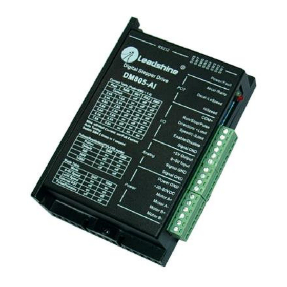
- Page 1 Hardware Installation Manual For DM805-AI A Digital Stepper Drive With Analogue 0-5V Input V1.0-150323 (March 2015) Motion Control Products Ltd. Innovative products for Automation Industry Tel.: (+44) 01202 599922...
- Page 2 Motion Control Product’s general policy does not recommend the use of its products in life support or aircraft applications wherein a failure or malfunction of the product may directly threaten life or injury.
- Page 3 DM805-AI Digital Stepper Drive Hardware Operation Manual HEALTH AND SAFETY Read this manual carefully before trying to install the stepper drive into your system. The person setup the stepper drive should have a better understanding on electronics and mechanics. Contact us if there is any Notice question about the products or this manual.
-
Page 4: Table Of Contents
DM805-AI Digital Stepper Drive Hardware Operation Manual Contents 1. INTRODUCTION, FEATURES AND APPLICATIONS .......... 1 Introduction....................... 1 Features ......................1 Applications ....................... 2 2. SPECIFICATIONS ..................2 Electronic Specification Tj = 25℃/77℉ ............. 2 Velocity Control ....................2 Operating Environment ..................3 Outline Dimensions ................... - Page 5 DM805-AI Digital Stepper Drive Hardware Operation Manual Pulse/Direction Mode ..................11 6. CONNECTING THE MOTOR ................ 12 4-lead Motors Connections ................12 6-lead Motors Connections ................12 Half Coil Configurations ................12 Full Coil Configurations ................13 8-lead Motors Connections ................13 Series Connections ..................13 Parallel Connections ..................14 7.
- Page 6 DM805-AI Digital Stepper Drive Hardware Operation Manual 11. PROTECTION FUNCTIONS ................ 23 Over-current Protection ................23 Over-voltage Protection ................23 Protection Indications ................. 24 12. FREQUENTLY ASKED QUESTIONS ............. 24 Problem Symptoms and Possible Causes ............25 APPENDIX ....................26 Twelve Month Limited Warranty..............
-
Page 7: Introduction, Features And Applications
1. INTRODUCTION, FEATURES AND APPLICATIONS Introduction Motion Control Products Ltd (MCP)’s digital stepper drive DM805-AI is a digital stepper drive with built-in oscillator, featured in supporting 0-5V analogue signal for speed controls. Using the latest digital control algorithm, it brings a unique level of system smoothness, providing optimum torque and nulls mid-range instability. -
Page 8: Applications
Hardware Operation Manual Applications DM805-AI stepper drive is suitable for the application which needs to adjust the velocity via the potentiometer or analogue 0-5V command. It can work with the size NEMA 17/23/34 stepper motors to replace the brushless motor with gearbox, due to the nature of its high torque and less motor noise at low speed. -
Page 9: Operating Environment
DM805-AI Digital Stepper Drive Hardware Operation Manual Operating Environment Cooling Natural Cooling or Forced cooling Avoid dust, oil fog and corrosive Environment gases Ambient Temperature 0ºC-50ºC (32ºF-122ºF) Operating Environment Humidity 40%RH-90%RH Operating Temperature 70˚C (158˚F) Max Vibration 5.9m/s -20ºC -65ºC (-4ºF -149ºF) -
Page 10: Connectors And Pin Assignment
Use forced cooling method to cool the system if necessary. 3. CONNECTORS AND PIN ASSIGNMENT The DM805-AI has three connectors, connector for digital I/O signals connections, connector for analog 0-5V signal connections and connector for power and motor connections. The three parameters are used to preset or adjust the speed, acceleration and deceleration ramp. -
Page 11: Operating Mode
It is used to configure and current loop tuning, anti-resonance tuning with the PC software. However, the drive can still work properly without it. The DM805-AI can be fully tuned by the auto-tuning. DIP switch: 8 bits, current setting, selecting microstep, operating mode 4. -
Page 12: Signal Sequence
Hardware Operation Manual Signal Sequence After power-up, the DM805-AI does not response to the analog 0-5V input immediately. The Enable and Run signal should be activated prior to the analog 0-5V input. The drive is enabled when the Enable/Disable input is unconnected and the motor shaft has holding torque at that time. -
Page 13: Low/High Speed Mode
DM805-AI Digital Stepper Drive Hardware Operation Manual potentiometer, the actual output ramp will be limited by the potentiometer value. Low/High Speed Mode In low/high speed mode, motor speed is fixed to the value adjusted by the LoSpeed or HiSpeed Potentiometer, depending on the level of Speed input. When the Speed input is LOW level, the maximum motor speed adjusted by the LoSpeed potentiometer is 5rps. -
Page 14: Signal Sequence
Hardware Operation Manual Signal Sequence After powering up, the DM805-AI does not make the motor run immediately. The Enable and Run signal should be activated firstly. Drive is enabled when the Enable/Disable input is unconnected. After Run signal is activated, the Speed can be applied to the drive for... -
Page 15: External Potentiometer Mode
DM805-AI Digital Stepper Drive Hardware Operation Manual External Potentiometer Mode In this mode motor speed follows the analog 0-5V input voltage. Motor speed is also proportional to the HiSpeed potentiometer. When the analog input is 0-2.5V, the motor runs in negative direction. While the analog input is 2.5-5V, the motor runs in positive direction. -
Page 16: Signal Sequence
DM805-AI Digital Stepper Drive Hardware Operation Manual Signal Sequence Ramp Shaping There are two potentiometers Accel and Decel for adjusting the acceleration ramp and deceleration ramp, respectively. When the input ramp exceeds the value set by the potentiometer, the actual output ramp will be limited by the potentiometer value. -
Page 17: Control Signal Requirement
Hardware Operation Manual 5. CONTROL SIGNAL REQUIREMENT Pulse/Direction Mode DM805-AI can support Pulse/Direction and CW/CCW control signal modes. In order to avoid some fault operations and deviations, PUL, DIR and ENA should abide by some rules, shown as following diagram: Remark: ENA must be ahead of DIR by at least 5us. -
Page 18: Connecting The Motor
DM805-AI Digital Stepper Drive Hardware Operation Manual 6. CONNECTING THE MOTOR The DM805-AI stepper drive can drive any 2-pahse and 4-pahse hybrid stepper motors. 4-lead Motors Connections 4-lead motors are the least flexible but easiest to wire. Speed and torque will depend on winding inductance. -
Page 19: Full Coil Configurations
DM805-AI Digital Stepper Drive Hardware Operation Manual Full Coil Configurations The full coil configuration on a 6-lead motor should be used in applications where higher torque at lower speeds is desired. This configuration is also referred to as full copper. In full coil mode, the motors should be run at only 70% of their rated current to prevent over heating issue. -
Page 20: Parallel Connections
The DM805-AI digital stepper drive can match small and medium size stepper motors (from NEMA frame size 14 to 34) supplied by Motion Control Products Ltd or other motor manufactures around the world. To achieve good performance, it is important to select the correct supply voltage and output current. -
Page 21: Multiple Drives
Instead, please connect them to power supply separately. Selecting Supply Voltage The power MOSFETS inside the DM805-AI stepper drive can actually operate with wider voltage range than the input specification. Higher supply voltage can increase motor torque at higher speeds, thus helpful for avoiding losing steps. -
Page 22: Typical Connection
8. TYPICAL CONNECTION Analogue 0-5V Speed Mode The 5V output of DM805-AI is connected to the COM+. The input signal is activated when it is short circuit to the signal GND. When the Limit switch is activated, the motor shaft will be free and the red indicator is on. -
Page 23: Low/High Speed Mode
DM805-AI Digital Stepper Drive Hardware Operation Manual Low/High Speed Mode Motion Control Products Ltd. P a g e | 1 7 www.motioncontrolproduts.com... -
Page 24: External Potentiometer Mode
DM805-AI Digital Stepper Drive Hardware Operation Manual External Potentiometer Mode Motion Control Products Ltd. P a g e | 18 Tel.: (+44) 01202 599922... -
Page 25: Pulse/Direction Mode
DM805-AI Digital Stepper Drive Hardware Operation Manual Pulse/Direction Mode A complete stepping system should include stepping motor, stepping drive, power supply and controller (pulse generator). Motion Control Products Ltd. P a g e | 1 9 www.motioncontrolproduts.com... -
Page 26: Wiring Notes
10. DRIVE CONFIGURATION The DM805-AI stepper drive uses an 8-bit DIP switch to set operating mode, microstep resolution and motor operating current as follows. The dynamic current setting by SW1, SW2 and SW3 is active for all operating mode. The microstep resolution setting by SW5 and SW6 only takes effect in Pulse/Direction mode. -
Page 27: Auto Configuration By Sw4
Sometimes the result of the auto-configuration is not good. This will happen to the stepper motor with large inductance or resistance. The user needs to tune the current loop parameter manually. Please refer to the software manual of the DM805-AI. Selecting Operating Mode... -
Page 28: Microstep Resolution Selection
DM805-AI Digital Stepper Drive Hardware Operation Manual Microstep Resolution Selection In Pulse/Direction mode, microstep resolution is selected by SW4 and SW5. The stepper motor moves one step when one pulse is applied to the stepper drive. If microstep is 1, the step angle is a full step which is 1.8 degree for 2-phase stepper motor and 1.2 degree for... -
Page 29: Idle Current Setting
Idle current setting When there is no pulse applied to the DM805-AI and the time exceeds the idle-time which can be configured via the PC based software, the drive goes into idle status. SW4 is used to set the idle-current, OFF meaning that the motor coil current is automatic reduced, and ON meaning that current is the same as the selected dynamic current. -
Page 30: Protection Indications
Technical Support staff in determining the problem should you need assistance. Many of the problems that affect motion control systems can be traced to electrical noise, controller software errors, or mistakes in wiring. -
Page 31: Problem Symptoms And Possible Causes
DM805-AI Digital Stepper Drive Hardware Operation Manual Problem Symptoms and Possible Causes Symptoms Possible Problems No power Microstep resolution setting is wrong Motor is not rotating DIP switch current setting is wrong Fault condition exists The drive is disabled Motor rotates in the... -
Page 32: Appendix
Motion Control Products Ltd. warrants its products against defects in materials and workmanship for a period of 12 months from the shipping date. During the warranty period, Motion Control Products will either, at its option, repair or replace products which are proved to be defective.
Need help?
Do you have a question about the DM805-AI and is the answer not in the manual?
Questions and answers