Table of Contents
Advertisement
Quick Links
Advertisement
Table of Contents

Related Manuals for Dionex AS-DV

Summary of Contents for Dionex AS-DV
- Page 1 AS-DV Autosampler Operator's Manual Document No. 065259 Revision 01 April 2009...
- Page 2 Dionex Corporation, 1228 Titan Way, Sunnyvale, California 94088-3603 U.S.A.
-
Page 3: Table Of Contents
Overview of the AS-DV ........ - Page 4 AS-DV Operator’s Manual 3 • Operation and Maintenance ......21 Preparing the Sample Vials ........21 3.1.1...
- Page 5 Contents 4 • Troubleshooting ........49 Alarms and Error Conditions .
- Page 6 Unpacking the AS-DV ........79...
- Page 7 Contents C.1.2 Delivery Speed, Flush Factor, and TTL Homing Delay Settings ........96 C.1.3 TTL Input Control Modes .
- Page 8 AS-DV Operator’s Manual Doc. 065259-01 4/09...
-
Page 9: Introduction To The As-Dv
(for example, an ICS- 900, ICS-1100, ICS-1600, ICS-2100, or ICS-3000). The AS-DV holds 50 vials (either 0.5 mL or 5.0 mL, or a combination of the two sizes). Vials can be sampled in any order and multiple samples can be taken from each vial. -
Page 10: About This Manual
AS-DV Operator’s Manual About This Manual 1.2.1 Overview The electronic version (i.e., PDF file) of the AS-DV operator’s manual contains numerous hypertext links that can take you to other locations within the file. These links include: • Table of contents entries •... -
Page 11: Safety Messages And Notes
This manual contains warnings and precautionary statements that, when properly followed, can prevent personal injury to the operator and/or damage to the AS-DV. Safety messages appear in bold type and are accompanied by icons, as shown here. Indicates an imminently hazardous situation which, if not avoided, will result in death or serious injury. -
Page 12: Safety And Regulatory Information
527 Lakeside Drive, Sunnyvale, CA 94088-3603 U.S.A. The AS-DV is designed for use with IC (ion chromatography) systems and should not be used for any other purpose. Operation of an AS-DV in a manner not specified by Dionex may result in personal injury. -
Page 13: Safety Labels
1 • Introduction to the AS-DV Safety Labels The EN 61010, cETLus, and CE safety marks on the AS-DV indicate that the AS- DV is in compliance with the following standards. EMC Susceptibility and Emissions • EN 61326-1:2006 Safety •... - Page 14 AS-DV Operator’s Manual Doc. 065259-01 4/09...
-
Page 15: Description
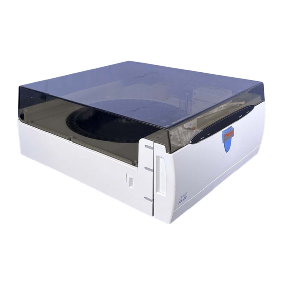
2 • Description Operating Features 2.1.1 Front View Figure 2-1 illustrates the main operating features of the AS-DV Autosampler. Vial Carousel Cover Carousel Carousel Release Button (Not visible in photo) Sampling Head Tower LED Display Front Cover Figure 2-1. AS-DV Front View... - Page 16 (see Figure 2-1). • The sampling head tower delivers sample from the sample vials to the sample out line, which exits the front of the AS-DV (see Section 2.1.2). For a description of how the sampling mechanism operates, see Section 2.2.1.
- Page 17 2 • Description • The carousel cover protects light-sensitive samples and the interior of the AS-DV. To access the sampling head tower and carousel, lift up the cover. To avoid trapping dust particles in the vial caps, always operate the AS-DV with the carousel cover closed.
- Page 18 Vial trays (either for 0.5 mL or 5.0 mL vials) are included in the respective AS-DV Ship Kit (P/N 071115, Ship Kit for 0.5 mL vials; P/N 068887, Ship Kit for 5.0 mL vials). Place vials into the tray and then fill them until the liquid in the vials reaches the top of the tray.
-
Page 19: Front Interior Features
The sample out line is routed from the sampling mechanism through an aperture in the front interior. From there, it is connected either to the high- pressure valve in the AS-DV (if installed) or to the injection valve in the IC system. -
Page 20: Rear Panel
Connector and Power Receptacle Figure 2-6. AS-DV Rear Panel Drain Liquid from any spills exits the AS-DV enclosure through the port. DRAIN Connect a drain hose (P/N 055075) to the port and place the free end of the hose into either a waste container or an appropriate drain. The drain hose is included in the AS-DV Ship Kit Neutralize acidic and caustic wastes before disposal. - Page 21 Connect a USB cable between the USB connector on the AS- DV and a USB port on the PC. Alternatively, the AS-DV can be connected to a hub or an IC system with a USB port. For USB connection...
-
Page 22: As-Dv Operating Principles
AS-DV Operator’s Manual AS-DV Operating Principles 2.2.1 Sampling Operating Principles The sampling head tower (see Figure 2-1) consists of a motor-driven needle, with a sampling tip on the end, that moves down to engage the top of the vial cap. -
Page 23: Rinsing Operating Principles
Section B.8.2). When performing a rinse, the AS-DV takes the rinse liquid from the first vial in the range. If the first vial is empty, the next vial in the range is used, and so on. To define rinse cycles in Chromeleon, see Section 3.8.3. - Page 24 Plumbing configurations for the valves depend on the components to be connected and the application to be run. Refer to the appropriate Dionex Application Note for more information. Operation as a Bleed Valve...
- Page 25 2 • Description IC System AS-DV Optional Valve Injection Valve To Column (A Position) (Load Position) AS-DV Sample Out Line (5) S L (4) Sample Loop Concentrator (6) W C (3) Column (1) L P (2) PolyVial From Pump To Waste To Waste Figure 2-10.
-
Page 26: Chromeleon Software
AS-DV Operator’s Manual Chromeleon Software The AS-DV is controlled by a PC running Chromeleon Chromatography Management System (version 6.80 SR6a or later). 2.3.1 Software Control Modes Two modes of software control are available: direct control and programmed control. • With direct control, you select operating parameters and commands... -
Page 27: System Wellness
System Wellness monitors the overall “health” of a chromatographic system. It provides built-in diagnostic and calibration features that help prevent unscheduled system shutdowns and assure reliable operation of system devices. Use the AS-DV Wellness Panel (see Figure 2-13) to monitor the usage of replaceable parts. After replacing a part, click Reset to reset the Current counter to 0. - Page 28 AS-DV Operator’s Manual Doc. 065259-01 4/09...
-
Page 29: Operation And Maintenance
Preparing the Sample Vials Dionex recommends thoroughly rinsing all PolyVials and caps with deionized water before filling to remove any traces of dust. Dionex DOES NOT recommend reusing vials or caps and does not guarantee their cleanness or proper operation if reused. -
Page 30: Cleaning The Caps
AS-DV Operator’s Manual 3.1.2 Cleaning the Caps Use the following procedure to clean caps without filters. For trace-level analyses, use caps without filters to avoid introducing contaminants from the filter. 1. Place caps into a clean 4-liter polyethylene container. Fill the container three-quarters full with deionized water and cap. -
Page 31: Filling The Vials And Installing The Caps
3 • Operation and Maintenance 3.1.4 Filling the Vials and Installing the Caps A cap must be installed in each vial in order for the autosampler to operate correctly. A vial without a cap will be sensed as an empty position. - Page 32 (the top of the cap is flush with the lip of the vial). The tool is provided in both AS-DV Ship Kits (for 0.5 mL vials, P/N 071115; for 5.0 mL vials, P/N 068887).
-
Page 33: Turning On The Power
Turning on the Power To turn on the autosampler power, press the power switch on the AS-DV rear panel (see Figure 2-6). At power-up, the sampling needle is homed (the needle is raised) and the carousel is homed (vial position 1 is moved under the sampling head tower). -
Page 34: Connecting To Chromeleon
AS-DV Operator’s Manual 8. If you are using 0.5 mL vials, twist the adapter slightly to the right to lock the adapter in place in the carousel. 9. Press the Carousel Release button again to engage the carousel with the motor and home the carousel. -
Page 35: Creating A Chromeleon Program
A Chromeleon program (sometimes called a PGM file) is a list of control commands to be executed at specified times. The program automates operation of the AS-DV. This section provides an overview of how to create a program with the Program Wizard. For detailed instructions, refer to the Chromeleon Help. - Page 36 The initial Program Wizard page is displayed. Figure 3-5. Program Wizard: Select Timebase Options 3. Select the Timebase in which the AS-DV is configured and click Next >. If the selected timebase includes other devices (for example, a pump and detector), Program Wizard pages for these devices are displayed before the AS-DV page.
- Page 37 3 • Operation and Maintenance 5. When the Sample Preparation Options page appears, select the desired options for AS-DV operation. Figure 3-6. Program Wizard: Sample Preparation Options Basic Loading Mode Select this option to use a set of basic commands to prepare samples.
- Page 38 AS-DV Operator’s Manual • Concentrator Mode: Select this option if the sample will be loaded to a concentrator column. The AS-DV is capable of delivering at a maximum pressure of 690 kPa (100 psi). • Bleed: Select this check box to deliver excess sample (and any trapped air) from the vial to waste, before delivering the injection volume to the sample loop or concentrator column.
-
Page 39: Creating A Chromeleon Sequence
The range is 0 to 500 µL. The default value of 125 µL is appropriate for the 1.4 m (56 in) length of sample out line provided with the AS-DV. • Cycle Time: Select the check box and enter a number of minutes to set a uniform time between injections. -
Page 40: Starting A Run
During a run, do not press the Carousel Release button. Doing so clears all current vial information from AS-DV memory. (During a run, the AS-DV stores the vial size installed in each carousel position and the remaining volume in each vial.) After creating the sequence, you can start sample processing. -
Page 41: Operating Details
• To interrupt the autosampler when a sequence is not running, click Stop on the AS-DV Control panel on the panel tabset. NOTE After the AS-DV stops its current operation, the carousel returns to the home position (position 1). - Page 42 AS-DV Operator’s Manual 2. If Basic Loading Mode is selected, select the Bleed check box (see Figure 3-8). Figure 3-8. Program Wizard Sample Preparation Options: Bleed Enabled Using the Injection Valve Selecting Bleed adds two commands to the Command/Parameters table (see Figure 3-8).
- Page 43 3 • Operation and Maintenance Enabling a Bleed Using the Optional High-Pressure Valve 1. If you are creating a new program, go to the Sample Preparation Options page of the Program Wizard. If you are editing an existing program, go to the Sample Preparation page of the Program Editor.
-
Page 44: Specifying A Rinse
AS-DV Operator’s Manual 3.8.3 Specifying a Rinse A rinse delivers rinse liquid from a vial to waste. To perform a rinse cycle, the AS-DV needs the following information: • The position of the vial containing the rinse liquid • The volume to use for rinsing Defining a Rinse Cycle 1. - Page 45 This section describes two methods for specifying a rinse vial position: Method 1: Specify a vial in the Rinse Vial Range 1. In the Server Configuration program, open the AS-DV Properties dialog box and click the Options tab page. Under Rinse Vial Range,...
- Page 46 3.8.3), enter Rinse for the vial position. See the example in Figure 3-11. When the AS-DV performs the rinse, it takes the rinse liquid from the first vial in the rinse vial range. If the first vial is empty, the next vial in the range is used, and so on.
-
Page 47: Returning To A Vial
4. Wait until the AS-DV carousel and sampling tip are not moving. Then lift the top cover, remove the old vials, and replace them with the new vials. Do not reach into the autosampler while the carousel is moving! Doc. -
Page 48: Inserting A Priority Sample
5. Wait until the AS-DV carousel and sampling tip are not moving. Then lift the top cover, remove the old vial (if any), and insert the priority vial in the carousel. Do not reach into the autosampler while the carousel is moving! Doc. -
Page 49: Controlling The Injection Volume
3 • Operation and Maintenance 3.8.7 Controlling the Injection Volume The AS-DV can deliver a full vial volume in one injection or deliver a partial vial volume in multiple injections. Defining a Full Vial Injection (Advanced Loading Mode Only) 1. On the Sample Preparation page of the Program Wizard or Editor (see Figure 3-14), select Advanced Loading Mode. - Page 50 AS-DV Operator’s Manual The DeliverSample Volume=Full command appears in the Commands view of the program (see Figure 3-15). Figure 3-15. Commands View Example: Deliver Full Vial Volume Defining Multiple Injections per Vial This section describes two methods for defining multiple injections per vial.
- Page 51 3 • Operation and Maintenance program) and select From Sequence for the Volume. If you are defining a program in Basic Loading Mode, no special action is required. In either case, the DeliverSample command appears in the Commands view of the program without a specified Volume (see Figure 3-16).
- Page 52 AS-DV Operator’s Manual Method 2 for multiple injections per vial (Advanced Loading Mode Only): In Advanced Loading Mode, you can enter the deliver volume in the Chromeleon program. 1. On the Sample Preparation page of the Program Wizard or Editor (see Figure 3-17), select Advanced Loading Mode.
- Page 53 3 • Operation and Maintenance The DeliverSample Volume=1000 command appears in the Commands view of the program (see Figure 3-15). Figure 3-18. Commands View Example: Deliver Multiple Injections Per Vial by Specifying the Volume NOTE The Program Wizard adds the DelayVolume and FlushFactor commands to the program automatically.
-
Page 54: Using Sample Overlap Mode
The AS-DV can be configured to overlap sample preparation functions. This means that while data collection is occurring for one injection, the AS-DV performs the sample preparation steps for the next injection in the sequence. The overlapped steps include AS-DV commands that occur before the EndSamplePrep command in the program. -
Page 55: Routine Maintenance
Routine Maintenance This section describes routine maintenance procedures that the user can perform for the AS-DV. Any maintenance procedures for the AS-DV that are not described here must be performed by Dionex personnel. To contact Dionex in the U.S., call 1-800-346-6390 and select the Technical Support option. - Page 56 AS-DV Operator’s Manual Doc. 065259-01 4/09...
-
Page 57: Troubleshooting
If you are unable to solve a problem by following the instructions here, contact Dionex Technical Support. In the U.S., call 1-800-346-6390. Outside the U.S., call the nearest Dionex office. Alarms and Error Conditions If any of the following alarm conditions occurs, an error message is displayed in the Chromeleon Audit Trail. - Page 58 AS-DV Operator’s Manual The table below lists the AS-DV error messages. For troubleshooting assistance, refer to the page indicated in the table Alarms and Error Conditions Default Severity Level Attempt to deliver an invalid vial. Error page 50 Attempt to reset vials while needle is not home.
- Page 59 4 • Troubleshooting 3. If the problem persists, contact Dionex for assistance. Attempt to reset vials while needle is not home. This error occurs if you attempt to reset vial memory, either by pressing the button or clicking a Reset Vial Memory button on the...
- Page 60 This error occurs when the needle is jammed or there is excessive backpressure. The motor speed is reduced and the AS-DV attempts to continue delivery. If the problem persists, the run is stopped, and the “Needle is jammed”...
- Page 61 2. If the problem persists, replace the sampling tip (see Section 5.3). 3. If the problem continues, contact Dionex for assistance. This command is not allowed at this stage because the autosampler is busy. This error occurs when a command is sent while the autosampler is performing another function.
- Page 62 NOTE Turning off the AS-DV power does not reset vial memory. c. On the AS-DV Control panel on the panel tabset, try to toggle the valve position by clicking first the Load (or Position A) button and then the Inject (or Position B) button.
- Page 63 AS-DV memory. For example, a 5.0 mL vial is installed in position 10, but the AS-DV expects a 0.5 mL vial to be installed in that position. Vial memory must be reset before starting a new run.
-
Page 64: Liquid Leaks
Old, previously-used caps or sample vials Do not reuse caps or sample vials. • Damaged tubing between sampling tip and optional high-pressure valve in the AS-DV or injection valve in the IC system Replace the sampling tip and tubing (see Section 5.3). - Page 65 4 • Troubleshooting • (TTL Input Control Only) Injection not made during homing delay before sample tip is retracted from sample: 1. Always switch the injection valve to Inject before the end of the homing delay following the last sample in the vial (see Section C.1).
-
Page 66: Unexpected Or Extraneous Peaks Detected
(see Appendix • USB cable not connected Make sure the USB cable is securely connected between the AS-DV and the Chromeleon PC or IC system. • Vial not sensed 1. Make sure that a cap is installed in each PolyVial. Vials without caps are... -
Page 67: Excessive Backpressure
Excessive Backpressure • Injection valve in wrong position On the AS-DV Control panel on the panel tabset, toggle the valve position. • Restriction in the liquid flow path 1. If the high backpressure persists, follow the liquid flow path backward from the injection valve, through the high-pressure valve (if installed), loosening fittings and reconnecting them until you locate the restriction. - Page 68 AS-DV Operator’s Manual Doc. 065259-01 4/09...
-
Page 69: Service
Refer to the warranty statement in the Dionex Terms and Conditions for more information. Replacing Tubing and Fittings The AS-DV is plumbed with the needle and tubing assembly listed below: Used for AS-DV Sampling Tip Kit (P/N 071575) -
Page 70: Removing The Carousel
Carousel Release position. 2. Turn off the AS-DV power and disconnect the power cord. Raise the top cover. 3. Remove the AS-DV front cover by gripping the indentations at each side and pulling the cover straight off toward you. - Page 71 5 • Service 5. Use a 3-mm Allen wrench to remove the set screw on the Sampling sampling head (see Head Figure 5-2). Remove the set screw Figure 5-2. Removing the Set Screw 6. Pull slightly on the sample out line to gain a small amount of slack in the line.
- Page 72 AS-DV Operator’s Manual 8. Lift the needle out of the carousel and set it to the right (see Figure 5-4). Lift the needle Set the needle to the right Figure 5-4. Lifting the Needle Out of the Carousel 9. Use a 2.5-mm Allen...
- Page 73 5 • Service 10. Unscrew the thumb screw on the carousel, and lift the carousel out of the autosampler. Figure 5-6. Removing the Carousel 11. Clear any blockages and clean the basin. 12. Align the holes on the bottom of the carousel Alignment Pins on Carousel with the pins on the top of the carousel shaft and reinstall the carousel.
-
Page 74: Replacing The Sampling Tip And Tubing
3. Turn off the AS-DV power and disconnect the power cord. Raise the top cover. 4. Remove the AS-DV front cover by gripping the indentations at each side and pulling the cover straight off toward you. - Page 75 5 • Service 6. Use a 3-mm Allen wrench to remove the set screw on the Sampling sampling head (see Head Figure 5-8). Remove the set screw Figure 5-8. Removing the Set Screw 7. Pull slightly on the sample out line to gain a small amount of slack in the line.
- Page 76 AS-DV Operator’s Manual 11. Thread the free end of the tubing up through the needle and screw the tip into place on the needle. 12. Continue threading the free end of the tubing up through the sampling head and out the aperture on the front of the AS-DV.
-
Page 77: Manually Raising The Sampling Head
The following tools are needed to complete this procedure: #1 Phillips screwdriver and 2.5-mm Allen wrench. 1. Turn off the AS-DV power and disconnect the power cord. Raise the top cover. 2. Remove the AS-DV front cover by gripping the indentations at each side and pulling the cover straight off toward you. - Page 78 AS-DV Operator’s Manual 4. Insert a 2.5 mm Allen wrench into the screw on top of the sampling mechanism (see Figure 5-11) and turn the wrench clockwise. The needle begins moving up. 5. Continue turning the wrench until the top of the sampling arm is even with the top of the sampling mechanism.
-
Page 79: Rebuilding A High-Pressure Valve
The following tools are needed to complete this procedure: 3-mm Allen wrench 1. Turn off the AS-DV power. The AS-DV power must be turned off before you rebuild a valve. If the power is on when you disconnect or connect the valve cable, the AS- DV will be damaged. - Page 80 AS-DV Operator’s Manual 5. Remove the 6-port or 10-port high-pressure valve: a. Use a 3-mm Allen wrench to remove the two screws holding the valve assembly in place (see Figure 5-13). Remove these 2 screws Figure 5-13. Removing the Valve Assembly b.
-
Page 81: Replacing A High-Pressure Valve Pod
The following tools are needed to complete this procedure: 3-mm Allen wrench 1. Turn off the AS-DV power. The AS-DV power must be turned off before you replace a valve pod. If the power is on when you disconnect or connect the valve cable, the AS-DV will be damaged. - Page 82 AS-DV Operator’s Manual 5. Remove the 6-port or 10-port high-pressure valve: a. Use a 3-mm Allen wrench to remove the two screws holding the valve assembly in place (see Figure 5-15). Remove these 2 screws Black Locking Ring Figure 5-15. Removing the Valve Assembly b.
- Page 83 11. Reinstall the valve assembly and reconnect all liquid lines. 12. Turn on the power to the AS-DV. 13. Start a test run to check for leaks from the valve. Tighten fittings as required. 14. Reinstall the front cover and close the top cover.
-
Page 84: Replacing The Main Power Fuses
1. Turn off the power switch on the AS-DV rear panel (see Figure 5-18). 2. Disconnect the main power cord from both its source and from the AS-DV rear panel. HIGH VOLTAGE—Disconnect the main power cord from its source and also from the rear panel of the AS-DV. -
Page 85: A • Specifications
A • Specifications A.1 Electrical Main Power 100 to 240 Vac, 50 to 60 Hz, 45 W (Auto-sensing power supply; no manual voltage or frequency adjustment required) Typical input power: 15 W Maximum line draw: 0.22 A at 110 Vac Fuses Two fast-blow IEC 127 fuses rated at 3.15 A (P/N 954745) A.2 Physical... -
Page 86: Sampling Mechanism
AS-DV Operator’s Manual A.4 Sampling Mechanism Carousel 50 vials Sample Capacity Materials All wetted surfaces are chemically inert plastic (polypropylene, ® ® ® polyethylene, PEEK™, Tefzel , Kel-F , or Teflon Delivery Type Programmable in Chromeleon: From 0.1 mL/min to 5.0 mL/min... -
Page 87: B • Installation
1. Open the AS-DV shipping container. Remove the AS-DV and place it on the workbench. 2. Unpack the AS-DV Ship Kit (for 0.5 mL vials, P/N 071115; for 5.0 mL vials, P/N 068887) and all other items included in the shipping container. Place the items in a convenient location and check them against the packing list. -
Page 88: Connecting The As-Dv Sample Out Line
AS-DV sample out line. 1. Raise the AS-DV top cover. 2. Remove the AS-DV front cover by gripping the indentations at each side and pulling the cover straight off toward you. The sample out line is threaded through an aperture in the chassis (see Figure B-1). -
Page 89: Connecting The Sample Out Line Directly To An Ic System
B • Installation Two connection options are available: • Connect the AS-DV sample out line directly to the injection valve in the IC system (see Section B.3.1). • Connect the AS-DV sample out line to an optional 6-port or 10-port high-... -
Page 90: Connecting The Sample Out Line To The Optional High-Pressure Valve
Installing the Optional Valve 1. Verify that the power to the AS-DV is off. The AS-DV power must be turned off before you install a valve. If the power is on when you connect or disconnect the valve cable, the AS- DV will be damaged. - Page 91 4. Remove the 6-port or 10-port valve from the AS-DV Valve Kit (6-port, P/N 068920; 10- port, P/N 068921). 5. Align the electrical cable with the connector on the back of...
- Page 92 AS-DV Operator’s Manual Plumbing the Optional Valve The plumbing configuration for the valve depends on the components to be connected and the intended function. This section provides instructions for the following configurations: • Plumbing the 6-port valve as an injection valve (see Figure B-5).
- Page 93 Route the other end of the tubing to a waste container. Make sure that the outlet of the waste line is below the level of the AS-DV and is not elevated at any point. 2. Connect the AS-DV sample out line: a.
-
Page 94: Connecting The Drain Line
4. To complete the 6-port valve plumbing for injection valve operation, refer to Figure B-6 and to the manual for the IC system. 5. Replace the front cover and close the top cover on the AS-DV. Continue to Section B.4. -
Page 95: Connecting The As-Dv To The Chromeleon Pc
DV rear panel and either a USB port on the Chromeleon computer or a USB port on the host IC system. A USB 2.0 external hub can be used to connect the AS-DV to the PC. Refer to the manual provided by the hub vendor for complete installation instructions. One or more hubs is required in the following situations: •... -
Page 96: Connecting The Power Cord
AS-DV Operator’s Manual B.7 Connecting the Power Cord 1. Verify that the power switch on the rear panel of the AS-DV is turned off. (The power switch may be turned on accidentally when the module is unpacked.) 2. Connect the power cord (IEC 320 C13) (ordered separately) from the main power receptacle on the rear panel to a grounded power source. -
Page 97: Setting Up Chromeleon
Monitor. The Server Monitor opens. Click Start to start the server. 4. Press the power switch on the AS-DV rear panel to turn on the power. 5. Windows automatically detects the new USB devices. A message flashes on the screen to inform you that new hardware was found. -
Page 98: Configuring The As-Dv In Chromeleon
1. Start the Chromeleon Server Configuration program (click Start on the Windows taskbar and click All Programs > Chromeleon > Server Configuration). 2. Add the AS-DV to an existing timebase or create a new timebase. 3. In the AS-DV Properties dialog box, click the Options tab (see Figure B-8). -
Page 99: Connecting To The Chromeleon Panel Tabset
B • Installation 4. If a high-pressure valve is installed, select the function for which the valve will be used: • To use the valve as an injection valve, click Injection. • To use the valve for another function (for example, a bleed valve), click Auxiliary. - Page 100 AS-DV Operator’s Manual 3. Click the Autosampler tab on the panel tabset to view the Control panel for the AS-DV (see Figure B-9). Figure B-9. Chromeleon Panel Tabset: AS-DV Control Panel Doc. 065259-01 4/09...
-
Page 101: Verifying Chromeleon Communication
Setting Up the AS-DV for Simultaneous Injections The simultaneous injection feature allows delivery of sample to two independent ion chromatography (IC) systems with one AS-DV and a computer running Chromeleon. The AS-DV and AS40 Simultaneous Injection Kit for ICS Systems (P/N 060258) provides the necessary parts and instructions for setting up this feature. - Page 102 AS-DV Operator’s Manual Doc. 065259-01 4/09...
-
Page 103: C • Relay Control Of The As-Dv
C-1) on the rear panel of the AS-DV Autosampler provides one relay output and one TTL input. Figure C-1. Relay Output and TTL Input Connector (on AS-DV Rear Panel) The relay output can be programmed in Chromeleon to switch any low-voltage device. -
Page 104: Ttl Input Function
When the input is triggered for the first time, the AS-DV performs a full vial delivery on vial position 1. When triggered again, the AS-DV performs a full vial delivery on vial position 2, and so on. -
Page 105: Ttl Input Control Modes
The default control mode, Normal Edge, is compatible with the output signals provided by Dionex products. If the device connected to the AS-DV does not send a normal edge signal, select the appropriate control mode. Refer to the documentation provided with the controlling device and the information below to determine the correct mode. - Page 106 1. Start the Chromeleon Server Configuration program (click Start on the Windows taskbar and click All Programs > Chromeleon > Server Configuration). 2. Under the timebase, double-click the AS-DV icon. The AS-DV Properties dialog box appears. 3. Click the TTL Inputs tab and then press the F2 key.
- Page 107 C • Relay Control of the AS-DV The Device Configuration dialog box appears (see Figure C-2). Figure C-2. Device Configuration Dialog Box: Selecting the TTL Input Control Mode 4. Select the TTL input control mode required by the controlling device from the Mode list.
-
Page 108: Connecting To The Relay Output And Ttl Input
When attaching wires to the connector plug, be careful not to allow stray strands of wire to short to an adjoining position on the connector. 3. Plug the connector into the 4-pin connector on the AS-DV rear panel (see Figure C-1). -
Page 109: Example Connections For Stand-Alone Operation
TTL-3 TTL-4 Figure C-4. Example TTL Input Connection: AS-DV Connected to IC20 Ion Chromatograph To control the AS-DV, set up an IC20 method that includes timed events for triggering on the AS-DV. Figure C-5 illustrates the timed events in an TTL IN example IC20 method. -
Page 110: Controlling The Relay Output
Figure C-5. IC20 Timed Events Example C.4 Controlling the Relay Output The AS-DV provides relay contacts for control of functions in external devices. The relay output can be programmed in Chromeleon to switch any low-voltage device. Switched current must be no more than 200 mA at 5 VDC. The relay- contact closures are normally open. - Page 111 C • Relay Control of the AS-DV 3. Expand the list of commands under Sampler and then under Sampler_Relay. 4. Execute the desired command (see the example in Figure C-6). Figure C-6. Chromeleon Commands Dialog Box: Example Relay Control Command...
- Page 112 AS-DV Operator’s Manual Controlling the Relay Output with a Program You can enter the commands on the Relay and State Devices Options page in the Program Editor or Program Wizard (see Figure C-7). Figure C-7. Chromeleon Program Wizard: Example Relay Output Control Command...
-
Page 113: D • Reordering Information
2.5 cm (1 in) 062980 Fitting, bolt, 10-32 043276 Fitting, ferrule, double-cone Kits 068920 6-Port High-Pressure Valve Kit 068921 10-Port High-Pressure Valve Kit 060258 AS-DV and AS40 Simultaneous Injection Kit for ICS Systems 045647 AS-DV Preventive Maintenance Kit Doc. 065259-01 4/09... - Page 114 AS-DV Operator’s Manual Part Item Quantity Number Miscellaneous Items 055075 Drain hose, convoluted, 10 mm (0.4 in) ID, 1.2 m (4 ft) long 954745 Fuse, IEC 127, rated 3.15 A Doc. 065259-01 4/09...
Need help?
Do you have a question about the AS-DV and is the answer not in the manual?
Questions and answers