Table of Contents
Advertisement
Quick Links
Advertisement
Table of Contents

Related Manuals for reflexmarine FROG XT10

Summary of Contents for reflexmarine FROG XT10
- Page 1 USER MANUAL Rev 0.2 Issue date: 13/04/2015 Original Instructions...
-
Page 2: Introduction
Please retain this manual for future reference. Additional copies may be obtained by contacting Reflex Marine or by downloading the latest version from www.reflexmarine.com/support. All information disclosed in this document is the property of Reflex Marine Ltd except where otherwise stated. -
Page 3: Table Of Contents
Contents Introduction ............................1 Product Specifications ........................4 Operating Parameters ........................5 General ........................... 5 Recommended Operating Parameters ................7 Using the FROG-XT10 ........................8 Safety Features ........................8 Passenger Instructions ......................8 Entry and Exit ........................9 Passenger Flow ........................10 Deck Crew Instructions ...................... - Page 4 Crane ............................ 37 Securing ..........................37 Inspection ..........................37 Preparation for Road Transport ..................37 Shipping ..........................37 Storage ..........................38 Feet Deformation during Storage ..................38 5.10 Replacement Parts ......................38 Replacement Parts ........................39 Introduction ......................... 39 Kits ............................39 Parts identification ......................
-
Page 5: Product Specifications
1 Product Specifications Table 1 Product Specifications Model No. XT10 Width 1 4090 mm Dimensions Width 2 (Across Buoyancy) 2660 mm (Nominal) Height 2180 mm Maximum Gross Mass 2120 kg Weight Tare Weight 970 kg Payload - SWL 1150 kg Frame 316l stainless steel, a4 stainless fixings Central Column / Load Plate... -
Page 6: Operating Parameters
2 Operating Parameters 2.1 General The FROG-XT10 has been designed to ensure passenger safety in the most demanding conditions. There are a large number of factors that affect the safe conduct of marine personnel transfers. These include: crew skill and experience, met-ocean conditions, landing areas, vessel station keeping capability and response to sea conditions, visibility and line of sight. - Page 7 Table 2 Operating Parameters FROG-XT10 Operational Sea State Limits Platform to Vessel Semi-sub to Vessel F.P.S.O. to Vessel Vessel to Vessel Significant Wave Height (m) Recommended Operating Limits XT10 Performance Limit Outisde Operating Limits Note: ▪ Recommended Operating Limit - This is the envelope in which it would normally be considered safe subject to due consideration of other risk factors.
-
Page 8: Recommended Operating Parameters
2.2 Recommended Operating Parameters Table 3 Recommended Operating Parameters Parameter Recommendation Wind Speed 40 knot (equivalent to 20 m/s) Crane Operator should have a clear view of the pickup and Visibility set down areas. Pitch 10⁰ Vessel Motion Roll 10⁰ Able to maintain position within a 5 m (16 ft) radius. -
Page 9: Using The Frog-Xt10
3 Using the FROG-XT10 3.1 Safety Features Protected Seating Position: Seats are positioned behind the buoyancy panels and framework. This provides maximum protection and minimises sense of exposure. The arrangement of the seats and individual entry / exit points allow rapid access and egress, allowing faster and more efficient transfers. -
Page 10: Entry And Exit
3.3 Entry and Exit Passenger entry and exit should only be conducted with the carrier in a stable position on deck as advised by the crane operator to the deck crew member in charge of the transfer operation. Note: All exiting passengers must be clear of the carrier before any new passengers attempt to board. -
Page 11: Passenger Flow
3.4 Passenger Flow Passengers can be loaded into the FROG-XT10 using either the different coloured harnesses or by using the seat numbering. 3.4.1 Seat Harness Colours 6 or Less Passengers When loading passengers should be seated in the 6 end seats (3 at either end). This will ensure faster loading times as each passenger will have their own dedicated entrance. - Page 12 3.4.2 Seat Numbering In order to perform loading efficiently and safely, the following procedures are recommended: Organise the passengers into groups of 10 (see note). Confirm that passenger and luggage weight does not exceed the SWL of the carrier. Split the passengers into three groups and assign each passenger a seat number Group A: 1, 2, 3, 4, 5 and 6 Group B: 7 and 8 Group C: 9 and 10...
-
Page 13: Deck Crew Instructions
3.5 Deck Crew Instructions Briefings Deliver passenger briefings prior to every transfer lift, it should contain the following information: Location specific instructions Loading and unloading procedures iii. Emergency procedures Potential hazards Seating position Other Responsibilities Highlight potential hazards to passengers e.g. trip hazards during entry/exit Remain alert from any hazards as they arise and take appropriate action iii. -
Page 14: Safety Harness Procedure
3.6 Safety Harness Procedure To make passenger entry more efficient, where possible, deck crew or passenger should loosen harness prior to entering the carrier. All passengers should be familiar with the seating procedure and practice entry prior to operations. Step 1 Step 2 Step 3 Enter the carrier... -
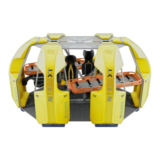
Page 15: Stretcher Mode
3.7 Stretcher Mode The following steps outline the procedure to convert the FROG-XT10 into stretcher mode. The FROG-XT10 can accommodate two stretchers, either both at the same time or one on its own. 3.7.1 Converting to Stretcher Mode For one stretcher, fold down the three seat backs behind buoyancy panels B and C (seats numbers1, 5 &... - Page 16 3.7.2 Stretcher Positioning The clamp channel has been designed to fit the Ferno Basket stretcher. However the clamp channel can be adjusted in height to accommodate the use of alternative stretcher types. Please note that not all stretcher types will fit. The clamp should be checked and adjusted to fit the specific stretcher type in use prior to operation.
- Page 17 3.7.3 Securing the Stretcher 1. Loosen the clamp thumbscrew, then pass the clamp through the hand hold in the stretcher 2. Turn clamp 90 degrees with folded edge upwards 3. Tighten clamp with thumb screw – this should be tight enough to prevent the stretcher from sliding longitudinally.
- Page 18 3.7.4 Seating Arrangement When using the FROG-XT10 in stretcher mode it is advised to keep the carrier evenly balanced, however it is understood that it is not always possible. The below images detail how to load the FROG-XT10 when in stretcher mode. 1 Stretcher When transporting only one stretcher up to 3 additional passengers may travel in the FROG- XT10.
-
Page 19: Carrying Luggage
3.8 Carrying Luggage Luggage may be transferred with passengers, however Reflex Marine recommend where practical, passenger luggage should be transferred separately in a cargo box or basket. This will minimise the risks from carrying out additional procedures whilst transferring personnel. Two types of luggage containers are available as accessories: an under-seat light luggage box for small handheld items or under-seat floor containers for larger kit bags. -
Page 20: Lifting Assembly Connection
3.9 Lifting Assembly Connection Figure 4 Lifting Assembly Lifting assembly is fitted to the FROG-XT by initially lowering it through the letter box openings at the top of the carrier. As there are two pairs of legs, one pair needs to go into each of the letterbox openings at the top of the unit. -
Page 21: Control Of Lifting Assembly
3.10 Control of Lifting Assembly The FROG-XT10 is designed to stay firmly on the deck of the vessel whilst passengers are entering or leaving the carrier. The Crane Operator must maintain slack in the line upon landing to allow for the vessel movement. Table 4 Control of lifting assembly Parameter Recommendation... -
Page 22: Inspection & Maintenance
4 Inspection & Maintenance 4.1 Introduction Following the recommended procedures set out in this section will help to ensure safe operation of the FROG-XT10. 4.2 Definitions Transfer Lift A transfer is defined as one pickup and put down when passengers are on board, or when the unit carries more than its tare weight. -
Page 23: Inspection Types
4.3 Inspection Types Table 6 Inspection Types Inspection Description Type A check of key areas prior to each use without dismantling the Pre-use Check assembly. Carried out by a competent person. A careful and critical assessment of the components, carried out by a Visual competent person without dismantling the assembly. -
Page 24: Supporting Documentation
Contact RML or one of our approved partners for technical advice on inspection, testing or maintenance. It is always helpful to provide detailed photos and reports along with any query to support@reflexmarine.com. 4.5 Supporting Documentation Customer drawing pack All FROG-XT10 units are accompanied by a drawing pack that contains all of the relevant drawings to aid in its maintenance. -
Page 25: Frog-Xt10 Inspection And Maintenance Schedules
4.6 FROG-XT10 Inspection and Maintenance Schedules Table 7 FROG-XT10 Inspection and Maintenance Recommendation FROG-XT10 RECOMMENDED INSPECTION AND MAINTENANCE SCHEDULES Load Test Usage Wire Rope Post Load Test Category Suspension Pre Use Visual Lifting Visual Unit Examination System Check Inspection Assembly Inspection Replacement No of Transfer... -
Page 26: Load Test Procedure
4.7 Load Test Procedure Table 8 Load Test Requirements Question Response After replacement of any critical parts. Does not apply to replacement of lifting assemblies. When should a After any suspected damage arising from overloading or Proof Load Test be impact. -
Page 27: Load Testing Arrangements
4.8 Load Testing Arrangements Figure 6 Main Lift Points Load Testing Arrangement Figure 7 Backup Lift Points Load Testing Arrangement Figure 8 Handling Eye Lift Points Load Testing Arrangement Rev 0.2 26 | P a g e... - Page 28 Inspection Data Plate An inspection data plate will be issued and attached by the test house, which should show: Tare Weight (kg) Pay load / SWL (kg) iii. Maximum gross load (kg) The load test date (DD/MMM/YYYY) Test load (kg) The serial number: XT10-XXX (where XXX is unit I.D.
-
Page 29: Pre Use Check
4.9 Pre Use Check Rev 0.2 28 | P a g e... -
Page 30: Visual Inspection Checklist Form
4.10 Visual Inspection Checklist Form FROG-XT10 Visual Inspection Checklist (Page 1 of 3) Unit Serial Number This Inspection Date Inspected by Usage Category Last Visual Inspection Position/ Company Installation / Vessel Last Examination Signature Avg. No of Transfers / Original Inspection Last Load Test Year record filed in... - Page 31 FROG-XT10 Visual Inspection Checklist continued… (Page 2 of 3) Item Comment / Serial Pass / Verified Description No./ Colour Code Fail Column A: Suspension Check the condition and operation of the springs. If the springs show excessive corrosion or have started to compress then they should be changed out.
- Page 32 FROG-XT10 Visual Inspection Checklist continued… (Page 3 of 3) Item Comment / Serial Pass / Verified Description No./ Colour Code Fail Stickers - Check that all of the stickers on the unit are in good condition and that none are missing or damaged.
-
Page 33: Examination Checklist Form
4.11 Examination Checklist Form FROG-XT10 Examination Checklist (Page 1 of 3) Unit Serial Number This Inspection Date Inspected by Usage Category Last Visual Inspection Position/ Company Installation / Vessel Last Examination Signature Avg. No of Transfers / Original Inspection Last Load Test Year record filed in Comment / Serial... - Page 34 FROG-XT10 Examination Checklist continued… (Page 2 of 3) Item Comment / Serial Pass / Verified Description No./ Colour Code Fail Suspension Column A: Check and test the condition and operation of the springs. If the springs show excessive corrosion or have started to yield then they should be changed out.
- Page 35 FROG-XT10 Examination Checklist continued… (Page 3 of 3) Item Comment / Serial Pass / Verified Description No./ Colour Code Fail Stickers - Check that all of the stickers on the unit are in good condition and that none are missing or damaged.
-
Page 36: Post Load Test Inspection Checklist Form
4.12 Post Load Test Inspection Checklist Form FROG-XT10 Post Load Test Inspection Checklist Unit Serial Number This Inspection Date Inspected by Usage Category Last Visual Inspection Position/ Company Installation / Vessel Last Examination Signature Avg. No of Transfers / Original Inspection Last Load Test Year record filed in... -
Page 37: Handling & Storage
5 Handling & Storage 5.1 Stock Inspections These guidelines are for the stocking of new units and parts before they are put into service. These guidelines are NOT applicable to units and parts that have already been put into service. Table 10 Stock inspections In Stock Release... -
Page 38: Forklift
5.2 Forklift Care should be taken when handling the FROG-XT10 with a forklift truck to avoid damage the underside (landing feet, cross braces or base of the central lifting column). Alternatively the capsule may be secured to a pallet specifically designed for use with forks. 5.3 Crane When lifting the FROG-XT10 with short chain or strop, a temporary shackle should be fixed to the handling lifting point. -
Page 39: Storage
5.8 Storage The FROG-XT10 has been designed to cope with the harsh conditions on an offshore installation or vessel; however it is important to protect the unit as much as possible from any hazardous elements and UV degradation. It is recommended that a FROG-XT10 weatherproof cover is used whilst not in use. -
Page 40: Replacement Parts
6 Replacement Parts 6.1 Introduction Replacement parts can be supplied as individual items or as appropriate kits. Prior to ordering any replacement parts or kits, establish the FROG-XT serial number which is stamped on the data plate. The serial number is XT10- XXX where XXX represents a three digit number. -
Page 41: Parts Identification
6.3 Parts identification Each assembly or part is assigned a part number which provides the unique identification of the part /assembly. Where material grades and material traceability are deemed to be safety critical these components will be allocated unique component numbers which will be stamped or etched as required. - Page 42 Luggage Options Light Luggage Holder This is a small holder that attaches to the underneath of 4 seats, allowing for small, hand- held items such as laptop bags to be loaded and transported by the FROG-XT10. Large Luggage Basket RML can provide a solution for larger items of luggage that will not fit into the light luggage holder.
-
Page 43: Certificates
7 Certificates 7.1 EC Attestation of Conformity Rev 0.2 42 | P a g e... -
Page 44: Contact Details
Reflex Marine, Old School House School Hill Shortlanesend Truro TR4 9DU Telephone: +44 (0)1872 321155 Email Addresses: General enquiries – info@reflexmarine.com Order enquiries (sales & replacement parts) – support@reflexmarine.com Accounts Department – accounts@reflexmarine.com Rev 0.2 43 | P a g e...
Need help?
Do you have a question about the FROG XT10 and is the answer not in the manual?
Questions and answers