Table of Contents
Advertisement
Quick Links
Advertisement
Table of Contents

Related Manuals for IHOS Quadro DSP 6.4 1500W Series


Summary of Contents for IHOS Quadro DSP 6.4 1500W Series
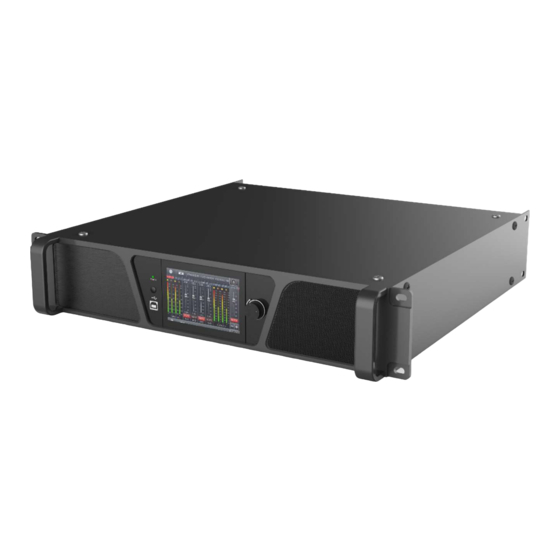
- Page 1 DSP DIGITAL POWER AMPLIFIER Quadro DSP 6.4 User Manual...
-
Page 2: Table Of Contents
DSP DIGITAL POWER AMPLIFIER Chapter 1: Introduction ................................2 Chapter 2: Technical Parameters ............................. 2 2.1 Features ................................... 2 2.2 Technical Parameters ..............................3 Chapter 3: Functions and Structure ............................4 3.1 Display panel description ............................... 4 Chapter 4: Software Introduction ............................. 7 Chapter 5: Software Installation ............................... -
Page 3: Chapter 1: Introduction
DSP DIGITAL POWER AMPLIFIER Chapter 1: Introduction This series is a multi-functional network DSP digital power amplifier. It can monitor the status of amplifier and adjust the function of DSP in real time remotely. Built-in DSP functions with compressor, limiter, noise gate, PEQ, matrix mixer, delay etc. -
Page 4: Technical Parameters
DSP DIGITAL POWER AMPLIFIER 2.2 Technical Parameters Model 4*1500W 4*1500W@8Ω Power 4*2000W@4Ω 2*3200W@8Ω Bridged Power Input Audio Source Analog, Sine wave, Pink noise, White noise, AES Input Volume Mute, Phase, Level detector Input EQ 31 bands EQ Attack time 1~2895ms, Release time 1~2895ms, Input Noise Gate Threshold level -120dBu~0dBu DSP Matrix... -
Page 5: Chapter 3: Functions And Structure
DSP DIGITAL POWER AMPLIFIER Display 4.3”IPS colorful capacitive touch display Audio Source Topology Phoenix terminal Line-out Audio limiter, high temperature, DC, high frequency, short circuit, back Protection electromotive force, peak current limiter, surge current limiter, start delay, power breaker protection, power supply overvoltage/undervoltage protection Mconsole for controlling all these devices: media matrix processor, audio PC Software processor, DSP power amplifier, DSP active amplifier module... - Page 6 DSP DIGITAL POWER AMPLIFIER Home screen Sensitive adjustment Select input source Operating mode Page 5 / 37...
- Page 7 DSP DIGITAL POWER AMPLIFIER Support channels link Preset interface Control and Dante IP setting Select screen saver mode freely Screensaver 1 Page 6 / 37...
-
Page 8: Chapter 4: Software Introduction
DSP DIGITAL POWER AMPLIFIER Screensaver 2 Chapter 4: Software Introduction Mconsole is a software for users to quickly interact with the parameters of one or more machines. It can store the configuration parameters of the device in a disk file to configure and parameter preset scenes for multiple machines or different places of use. -
Page 9: Chapter 6 Software Interface Description
DSP DIGITAL POWER AMPLIFIER 5.3 Software operating Steps: Double-click the executable file in the folder to enter the software theme interface as shown in Figure 5.1. Precautions: Some connection methods do not support multiple host computers to be turned on at the same time. Please keep at most one software for each PC. -
Page 10: Initial Interface
DSP DIGITAL POWER AMPLIFIER 2 3 4 Figure 6.1 As shown in Figure 6.1, main screen all parts in yellow corresponding position as follows: (1) Menu bar (2) Scan button (3) Setting button (4) Link button (5) Device list (6) Module button (7) Homepage monitor area (8) Module function interface (9) List of input and output channels... - Page 11 DSP DIGITAL POWER AMPLIFIER Figure 6.1.1 1. Showed in Figure 6.1.1, click , the device can be switched of POWER ON or STANDBY, green means POWER the ON state, yellow means STANDBY state. 2. Click , you can make the display screen and status light of the connected device flash, and you can quickly find the connected device from the power amplifier device stack.
- Page 12 DSP DIGITAL POWER AMPLIFIER Figure 6.1.3 1. As shown in Figure 6.1.3, is the total volume push button, you can use the mouse to drag, or you can directly enter the exact value in the input box is the mute button. 2.
-
Page 13: Menu Bar
DSP DIGITAL POWER AMPLIFIER your needs. When the limiter is in the on-control state, the overload light will light up. 6.2 Menu bar 6.2.1 File Figure 6.2.1 File menu As shown in Figure 6.2.1 "File" menu: New Project: the software can create a model of demo device in this menu when the device is not connected. New Device: increase simulation equipment, simulation equipment will not affect the existing equipment. - Page 14 DSP DIGITAL POWER AMPLIFIER 6.2.3 Connection Figure 6.2.3 Connection menu As shown in Figure 2.5 "Connect" menu: Port: set the connection mode, port number and baud rate. Connect: connect and download the device parameters. Disconnect: disconnect the connected device. Connect all devices: connect and download the device parameters of all devices in the device list. Disconnect all devices: disconnect all connected devices in the device list.
-
Page 15: Scan
DSP DIGITAL POWER AMPLIFIER Recall: call the existing preset in the device. Delete: delete existing preset, default presets cannot be deleted or overwritten. Clear: delete all presets in the device. Boot: select a certain preset, after set to boot file, each time the device is powered on, the preset parameter is automatically called. -
Page 16: Link
DSP DIGITAL POWER AMPLIFIER Figure 6.2.7 Port connection interface 6.5 Link To set the parameters of multiple devices at the same time, click the "Link" button, and the network link interface as shown in Figure 6.2.8 will pop up. Select the device that needs to be set at the same time in the left frame, move to the link group in the middle frame, and then select the grouping setting parameters on the right, finally press the "OK"... -
Page 17: Local Ip Address
DSP DIGITAL POWER AMPLIFIER the device list, which is convenient for the user to interact with the required device and to operate multiple devices at the same time. 6.7 Local IP address When the software is opened, it will automatically obtain the IP address of the network connection corresponding to the network adapter of the current computer system, and display it in the lower left corner of the software to facilitate the management of the device IP address. -
Page 18: List Of Input And Output Channels
DSP DIGITAL POWER AMPLIFIER Each function module is opened and closed by the control key, and the function page and detailed parameters are displayed, and detailed settings can be made, and single or multiple functions can be operated freely. You can drag left and right to switch pages with different functions. -
Page 19: Test Signal Function
DSP DIGITAL POWER AMPLIFIER Figure 7.1 input channel module As shown in Figure 7.1, you can operate the polarity, mute, and input source sensitivity in the corresponding input channel; In the sensitivity setting, you can choose between 0dBu and 6dBu two gears 7.2 Test signal function Select sine wave, pink noise, white noise in the input source, and then set the corresponding parameters in the test signal settings according to your requirements to test the channel. -
Page 20: Input Channel Noise Gate
DSP DIGITAL POWER AMPLIFIER In the test signal generation setting, the three test signals can be set to generate the corresponding gain value of the test signal. The switch button on the right side of each test signal can control whether the test signal is effective. Green is on, red is off, and you can set frequency of sine wave. -
Page 21: Input Channel Peq
DSP DIGITAL POWER AMPLIFIER the value. 7.4 Input channel PEQ Double-click in the module button to pop up the input equalizer setting module as shown in Figure 7.3. The button in the upper right corner of the module can magnify this module, and the interface display will be clearer after magnification. - Page 22 DSP DIGITAL POWER AMPLIFIER 7.4.2 Multi-channel EQ curve display Figure 7.4.1 As shown in Figure 7.4.1, on the left is the EQ curve display switch of each channel. When it is turned on, the curve of the corresponding channel will be drawn in the EQ curve chart. 7.4.3 EQ control As shown in Figure 7.4.1, under the curve chart, all EQ controls...
-
Page 23: Matrix Mix
DSP DIGITAL POWER AMPLIFIER Figure 7.4.2 EQ Preset Select the item corresponding to the gear list on the left, and then click the function button on the right to realize the archive, call, delete, and rename functions of the equalizer setting parameters. 7.5 Matrix mix Double-click in the module button , the following Figure 7.5 matrix mixing setting module will pop up. -
Page 24: Output Peq
DSP DIGITAL POWER AMPLIFIER The numerical value box with the value is the input and output channel mixing key. When the mixing key is lit (double- click the value box to switch the state), the input channel and the output channel signal realizes the mixing function. The right part of the above figure contains the gain, reset button, and clear button of the matrix mix. -
Page 25: Output Compressor
DSP DIGITAL POWER AMPLIFIER to intuitively adjust the delay value of the corresponding channel, or enter the corresponding value in the value box , and the delay function is on the right. Switch, red is off, green is on, the reset button on the far right can directly reset the default value of the channel delay. -
Page 26: Output Module
DSP DIGITAL POWER AMPLIFIER Figure 7.7 Output limiter setting module 7.10 Output module Double-click in the module button , and the output setting module shown in Figure 7.8 pops up. Figure 7.8 Output setting module Page 25 /... -
Page 27: Input Channel
DSP DIGITAL POWER AMPLIFIER As shown above, you can control the polarity and mute setting of the corresponding output channel. 7.11 Input channel As shown in Figure 6.1, list of input and output channels homepage, the left part is the input channel as shown in Figure 7.9. -
Page 28: Output Channel
DSP DIGITAL POWER AMPLIFIER 6. In the button bar between the input and output channels is the master switch corresponding to the function button of all input and output channels, which will directly operate all input channels at the same time. 7.12 Output channel As shown in Figure 6.1, list of input and output channels homepage, the right part is the output channel as shown in Figure 7.10. -
Page 29: Channels Link
DSP DIGITAL POWER AMPLIFIER box, gain slider) are for adjusting the gain value of this channel. 2. Among the function buttons, the buttons from top to bottom are: mute , equalizer bypass , delay , compressor , limiter r, polarity , if the mute button is red, it is in mute state, and if the other buttons are green , It is the effective state. -
Page 30: Device List
DSP DIGITAL POWER AMPLIFIER 7.14 Device list The device list is on the left of software homepage shown in Figure 6.1, shown in Figure 7.11 Device List below: Figure 7.11 Device List The above figure is the connected device number; is the device name;... -
Page 31: Device Management
DSP DIGITAL POWER AMPLIFIER Figure 7.12 Add new device interface 7.16 Device management Click "Device"-"Devices" in the menu bar of the software homepage interface in Figure 6.1, and the device manage interface shown in Figure 7.13 will pop up. Figure 7.13 Device manage interface As shown in the figure above, the device information content displayed on the target device management interface can be selected in the device list at the top. -
Page 32: Channels Copy
DSP DIGITAL POWER AMPLIFIER Figure7.12 Channels names management As shown in the figure above, after entering the new name of the channel in the corresponding channel, click the OK button to save and update the name of the channel immediately. Note that the length of the channel name is limited to 5 English letters and numbers. -
Page 33: Preset
DSP DIGITAL POWER AMPLIFIER Figure 7.13 Channels copy interface As shown in the figure above, channel copy is to first select the channel parameters of a source device and copy to the target channel of other target devices. Input channels and output channels cannot copy each other. The left side is the corresponding channel, and the right side is the copied parameter. -
Page 34: Firmware Update
DSP DIGITAL POWER AMPLIFIER archived parameter package files. 7.20 Firmware update Click "System"-"Upgrade" in the menu bar of the software homepage interface in Figure 6.1, and the firmware upgrade interface shown in Figure 7.15 will pop up. Figure 7.15 Firmware upgrade interface When the lower computer system of the device has been updated, after obtaining the upgrade file, you can open the firmware upgrade interface as shown in the figure above. - Page 35 DSP DIGITAL POWER AMPLIFIER 1. There are two methods to connect DANTE. The first one is to connect to the LAN with other Dante devices, and the second is to connect via Dante Virtual Soundcard (DVS). Both methods need to via a switch or router in wired connection. 2.
-
Page 36: Fir Using Introduction
DSP DIGITAL POWER AMPLIFIER 7.22 FIR using introduction Double click FIR module button ,enter into FIR function interface, click Design to enter into design interface. There are 5 area in FIR interface: IMPORT Import FIR preset files to the current channel Setting ①... - Page 37 DSP DIGITAL POWER AMPLIFIER Bypass function, the channel EQ is straight after turned on, default red BYPASS state means turned on, and it needs to be turned off manually when using STORE Save FIR parameters in the device Taps Tap numbers of current channel Delay of current channel Name FIR preset file name of current channel...
Need help?
Do you have a question about the Quadro DSP 6.4 1500W Series and is the answer not in the manual?
Questions and answers