
Related Manuals for IHOS Quadro DSP 2.0


Summary of Contents for IHOS Quadro DSP 2.0
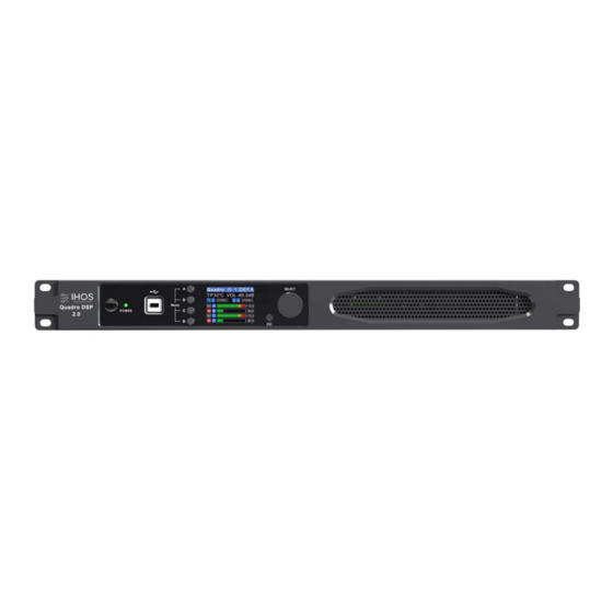
- Page 1 Multi- Functional DSP Network Digital Power Amplifier DSP DIGITAL POWER AMPLIFIER Quadro DSP 2.0 User Manual V1. 1 Page 1 / 37...
- Page 2 DSP DIGITAL POWER AMPLIFIER Multi- Functional DSP Network Digital Power Amplifier Menu Chapter 1 Introduction ---------------------------------------------------- Chapter 2 Technical parameters ---------------------------------------- Chapter 3 Functional Structure ------------------------------------------- Chapter 4 Software Introduction ------------------------------------------ Chapter 5 Software Installation ----------------------------------------- Chapter 6 Software Interface Description ------------------------------------------ 10 Chapter 7 Introduce of function interface -------------------------------------- Multi- Functional DSP Network Digital Power Amplifier...
-
Page 3: Chapter 1 Introduction
DSP DIGITAL POWER AMPLIFIER Chapter 1 Introduction This is a DSP digital amplifier of 4*500W@4Ω / 4*300W@8Ω ,Bridge 2*1000W@8Ω , support constant pressure 70V/ 100V(1 000W@10Ω ). It can monitor the status of amplifier and adjust the function of DSP in real time and remotely. DSP functions of built-in: noise gate, matrix mixer, PEQ, crossover, delay, compressor etc. -
Page 4: Chapter2 Technical Parameters
DSP DIGITAL POWER AMPLIFIER Chapter2 Technical Parameters Input PEQ 15 PEQS Output PEQ 10 PEQS Butterworth 、 Bessel 、 Linkwitz 6~24 Crossover Output Delay Input Delay:2*100ms / Output Delay:4*20ms Output Compressor Knee, Threshold, Attack, Ratio, Release Output Limiter Threshold-90dBu~21dBu 、 Release 1~2895ms 30 (one for factory preset) DSP Presets Control port... -
Page 5: Functional Structure
DSP DIGITAL POWER AMPLIFIER Multi- Functional DSP Network Digital Power Amplifier Chapter 3 Functional Structure Structure Page 5 / 37... -
Page 6: Display Interface
DSP DIGITAL POWER AMPLIFIER Multi- Functional DSP Network Digital Power Amplifier 3.1 Display interface 3.1.1Main page Page 6 / 37... - Page 7 DSP DIGITAL POWER AMPLIFIER Multi- Functional DSP Network Digital Power Amplifier 3.1.2 Menu page Page 7 / 37...
- Page 8 DSP DIGITAL POWER AMPLIFIER Multi- Functional DSP Network Digital Power Amplifier Mconsole is a software for users to quickly interact with the parameters of one or more machines. It can store the configuration parameters of the device in a disk file to configure and parameter preset scenes for multiple machines or different places of use.
- Page 9 DSP DIGITAL POWER AMPLIFIER Multi- Functional DSP Network Digital Power Amplifier This software is a green version, the green version of the software does not need to install the main program, the folder contains the following files or folders, all of which are indispensable. The green version of the software does not include the Microsoft .NET Framework 4.0 runtime.
- Page 10 DSP DIGITAL POWER AMPLIFIER Multi- Functional DSP Network Digital Power Amplifier Figure 6.1 As shown in Figure 6.1, main screen all parts in yellow corresponding position as follows: Multi- Functional DSP Network Digital Power Amplifier Figure 6.1.1 Page 11 / 37...
- Page 11 DSP DIGITAL POWER AMPLIFIER Showed in Figure 6 . 1 . 1 , click , the device can be switched of POWER ON or STANDBY, green means POWER the ON state, yellow means STANDBY state. Click , you can make the display screen and status light of the connected device flash, and you can quickly find the connected device from the power amplifier device stack.
- Page 12 DSP DIGITAL POWER AMPLIFIER 1. As shown in Figure 6.1.3, is the total volume push button, you can use the mouse to drag, or you can directly enter the exact value in the input box is the mute button. 2. When the input is overloaded, the indicator light will light up as follows 3.
- Page 13 DSP DIGITAL POWER AMPLIFIER 6.2.1 File Figure 6.2.1 File menu As shown in Figure 6.2.1 "File" menu: : the software can create a model of demo device in this menu when the device is not connected. : increase simulation equipment, simulation equipment will not affect the existing equipment. : open an existing device management project from the computer disk.
- Page 14 DSP DIGITAL POWER AMPLIFIER 6.2.3 Connection Figure 6.2.3 Connection menu As shown in Figure 2.5 "Connect" menu: : set the connection mode, port number and baud rate. : connect and download the device parameters. : disconnect the connected device. : connect and download the device parameters of all devices in the device list. : disconnect all connected devices in the device list.
- Page 15 DSP DIGITAL POWER AMPLIFIER : import multiple preset package files from the computer. : pack multiple presets in the device archive into one preset package and export to the computer to generate the preset package file. 6.2.5 System Figure 6.2.5 System menu As shown in Figure 6.2.5 "System"...
- Page 16 DSP DIGITAL POWER AMPLIFIER Figure 6.2.7 Port connection interface To set the parameters of multiple devices at the same time, click the " Link" button, and the network link interface as shown in Figure 6.2.8 will pop up. Select the device that needs to be set at the same time in the left frame, move to the link group in the middle frame, and then select the grouping setting parameters on the right, finally press the "...
- Page 17 DSP DIGITAL POWER AMPLIFIER When the software is opened, it will automatically obtain the IP address of the network connection corresponding to the network adapter of the current computer system, and display it in the lower left corner of the software to facilitate the management of the device IP address.
- Page 18 DSP DIGITAL POWER AMPLIFIER Double -click in the module button , and the following figure 7.1 channel input module will pop up. Figure 7.1 input channel module As shown in Figure 7 . 1 , you can operate the polarity, mute, and input source sensitivity in the corresponding input channel;...
- Page 19 DSP DIGITAL POWER AMPLIFIER Select sine wave, pink noise, white noise in the input source, and then set the corresponding parameters in the test signal settings according to your requirements to test the channel. In the test signal generation setting, the three test signals can be set to generate the corresponding gain value of the test signal.
- Page 20 DSP DIGITAL POWER AMPLIFIER Figure 7.2 input noise gate setting module As shown in Figure 7.2 above, click the noise gate switch in the upper right corner to turn on or the noise gate function of the channel input signal. The green is on, the red is off. The attack time, release time, and threshold level are the parameter corresponding to the noise gate.
- Page 21 DSP DIGITAL POWER AMPLIFIER Figure 7.3 Input PEQ setting module 7.4.1 Function button As shown in Figure 7.3 above, the functions of the top buttons are: : display the phase curve of the current channel. : show or hide all balance control points. : turn on or off all equalizer EQ of the current channel at the same time : save the current equalizer setting parameters to the computer, and recall and overwrite the existing equalizer parameters.
- Page 22 DSP DIGITAL POWER AMPLIFIER Figure 7.4.1 As shown in Figure 7.4.1, on the left is the EQ curve display switch of each channel. When it is turned on, the curve of the corresponding channel will be drawn in the EQ curve chart. 7.4.3 EQ control As shown in Figure 7.4.1, under the curve chart, all EQ...
- Page 23 DSP DIGITAL POWER AMPLIFIER Figure 7.4.2 EQ Preset Select the item corresponding to the gear list on the left, and then click the function button on the right to realize the archive, call, delete, and rename functions of the equalizer setting parameters. Double -click in the module button , the following Figure 7.5 matrix mixing setting module will pop up.
- Page 24 DSP DIGITAL POWER AMPLIFIER channel. The numerical value box with the value is the input and output channel mixing key. When the mixing key is lit ( double - click the value box to switch the state) , the input channel and the output channel signal realizes the mixing 23 / 37...
- Page 25 DSP DIGITAL POWER AMPLIFIER function. The right part of the above figure contains the gain, reset button, and clear button of the matrix mix. Click the value box on the left, and then drag the sliding block of the matrix mix gain or enter a value in the value box to adjust the matrix block Click the reset button to reset the matrix mixing function to the initial one -to -one state;...
- Page 26 DSP DIGITAL POWER AMPLIFIER left to intuitively adjust the delay value of the corresponding channel, or enter the 24 / 37...
- Page 27 DSP DIGITAL POWER AMPLIFIER corresponding value in the value box , and the delay function is on the right. Switch, red is off, green is on, the reset button on the far right can directly reset the default value of the channel delay. Note: ft = inches, cm = centimeters, ms = milliseconds Double -click in the module button , the following Figure 7.7 output compressor setting module will pop up.
- Page 28 DSP DIGITAL POWER AMPLIFIER Figure 7.7 Output limiter setting module Double -click in the module button , and the output setting module shown in Figure 7.8 pops up. 26 / 37...
- Page 29 DSP DIGITAL POWER AMPLIFIER Figure 7.8 Output setting module As shown above, you can control the polarity and mute setting of the corresponding output channel. 26 / 37...
- Page 30 DSP DIGITAL POWER AMPLIFIER As shown in Figure 6.1, list of input and output channels homepage, the left part is the input channel as shown in Figure 7.9. Figure 7.9 Input channel 1. The contents from top to bottom in the input channel interface include: channel name , input mode , channel gain, function buttons...
- Page 31 DSP DIGITAL POWER AMPLIFIER button of all input and output channels, which will directly operate all input channels at the same time. As shown in Figure 6 . 1 , list of input and output channels homepage, the right part is the output channel as shown in Figure 7.10.
- Page 32 DSP DIGITAL POWER AMPLIFIER 3 . The channel grouping joint debugging situation shows the default 4 channel joint debugging grouping. When the background color of the corresponding number box turns to yellow , it means that this channel has been added to the second group for joint debugging.
- Page 33 DSP DIGITAL POWER AMPLIFIER Click the joint adjustment button between list of input and output channels shown in Figure 6 . 1 , and following Figure 7.10 channels link interface will pop up. Figure 7.10 Channels link interface As shown in the figure above, the three lists from left to right are divided into channel list, group list, and parameter list: The channel list has listed all the channels that can be tuned together.
- Page 34 DSP DIGITAL POWER AMPLIFIER Figure 7.11 Device List 29 / 37...
- Page 35 DSP DIGITAL POWER AMPLIFIER The above figure is the connected device number; is the device name; is the factory name ( the user cannot modify) ; if the connection method is TCP, the left side of the factory name will display the network IP address of the device;...
- Page 36 DSP DIGITAL POWER AMPLIFIER Figure 7.13 Device manage interface As shown in the figure above, the device information content displayed on the target device management interface can be selected in the device list at the top. The device management interface is divided into four parts as follows: : display the current device's upper and lower computer version number and date information.
- Page 37 DSP DIGITAL POWER AMPLIFIER Figure7.12 Channels names management As shown in the figure above, after entering the new name of the channel in the corresponding channel, click the OK button to save and update the name of the channel immediately. Note that the length of the channel name is limited to 5 English letters and numbers.
- Page 38 DSP DIGITAL POWER AMPLIFIER As shown in the figure above, channel copy is to first select the channel parameters of a source device and copy to the 32 / 37...
- Page 39 DSP DIGITAL POWER AMPLIFIER target channel of other target devices. Input channels and output channels cannot copy each other. The left side is the corresponding channel, and the right side is the copied parameter. The "input" and "output" buttons at the top of the interface can switch the channel type for copying.
- Page 40 DSP DIGITAL POWER AMPLIFIER Click "System" -"Upgrade" in the menu bar of the software homepage interface in Figure 6.1, and the firmware upgrade interface shown in Figure 7.15 will pop up. Figure 7.15 Firmware upgrade interface When the lower computer system of the device has been updated, after obtaining the upgrade file, you can open the firmware upgrade interface as shown in the figure above.
- Page 41 DSP DIGITAL POWER AMPLIFIER second is to connect via Dante Virtual Soundcard (DVS). Both methods need to via a switch or router in wired connection. 2. Either which connection method is chosen, it is necessary to configure the routing through the official Dante Controller computer software.
- Page 42 DSP DIGITAL POWER AMPLIFIER There are 5 area in FIR interface: Import FIR preset files to the current channel IMPORT Export current channel FIR file EXPORT Bypass function, the channel EQ is straight after turned on, default red state means turned on, and it needs to be turned off manually when using BYPASS Setting ①...
- Page 43 DSP DIGITAL POWER AMPLIFIER Click to display the FIR curve of the corresponding channel, and support Channels ② 1, 2, 3, 4 36 / 37...
- Page 44 DSP DIGITAL POWER AMPLIFIER multiple curves to be displayed at the same time Design Design interface switch button Interface show with amplitude curve Magnitude Interface show with phase curve Function ③ Phase Show content within 72dB of amplitude accuracy 72dB Show content within 144dB of amplitude accuracy 144dB Amplitude accuracy, the value used for reference when the current display...
Need help?
Do you have a question about the Quadro DSP 2.0 and is the answer not in the manual?
Questions and answers