Table of Contents
Advertisement
Advertisement
Table of Contents

Related Manuals for TGM CAH-F18CGR1-FQA-E3

Summary of Contents for TGM CAH-F18CGR1-FQA-E3
- Page 1 Technical Manual R410A 208/230V 1Ph 60Hz 15 SEER Wall Mounted Air Handler Unit...
-
Page 2: Table Of Contents
15 SEER WALL MOUNTED AIR HANDLER SYSTEM TECHNICAL MANUAL Part 1. General Information 1. Nomenclature 2. Model Names of Indoor/Outdoor Units 4. Features Part 2. Indoor Unit Features Specification Dimension Service Space Wiring Diagrams 6. Electric Characteristics 7. Electrical Wiring 8. Field Wiring Part 3 Outdoor Unit 1. -
Page 3: Nomenclature
15 SEER AIR HANDLER SYSTEM TECHNICAL MANUAL 1. Nomenclature 1.1 Indoor unit 1.2 Outdoor unit 2. Model Names of Indoor/Outdoor Units 2.1 Indoor Units Model name Dimension(W×H×D)(inch) Power supply 15 SEER Cooling Only CAH-F18CGR1-FQA-E3 20-2/3×36-1/2×15 208/230V-1Ph-60Hz CAH-F24CGR1-FQA-E3 20-2/3×36-1/2×15 208/230V-1Ph-60Hz CAH-F30CGR1-FQB-E3 22×39-1/2×19 208/230V-1Ph-60Hz CAH-F36CGR1-FQB-E3 22×39-1/2×19 208/230V-1Ph-60Hz 2.2 Outdoor Units... -
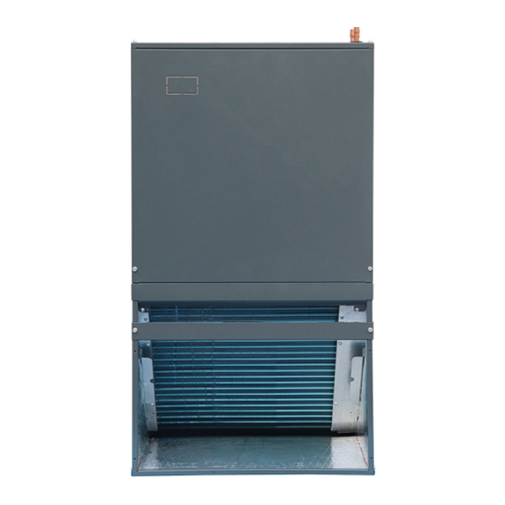
Page 4: External Appearance
15 SEER AIR HANDLER SYSTEM TECHNICAL MANUAL 3. External Appearance 3.1 Indoor unit 3.2 Outdoor unit Note: Standard outdoor unit is using plastic grill. Metal grill can be customized. -
Page 5: Features
15 SEER AIR HANDLER SYSTEM TECHNICAL MANUAL 4. Features 4.1 Operation features • Long Piping & Cost Effective • Low noise operation, as low as 48dB(A) • 24V control, Two-stage fan speed control, anti-cooling fan delay, heating fan delay and transformer included. 4.2 Performance features •... -
Page 6: Part 2. Indoor Unit
14SEER AIR HANDLER SYSTEM TECHNICAL MANUAL Part 2. Indoor Unit 1.Features 2.Specification 3.Dimension 4.Service Space 5.Wiring Diagrams 6.Electric Characteristics 7.The Specification of Wiring 8.Field Wiring... -
Page 7: Features
14SEER AIR HANDLER SYSTEM TECHNICAL MANUAL 1. Features (1) “A” shape coils, constructed with Inner-grooved oxygen free copper pipe and enhanced aluminum fins. (2) ECM motors, the air handler has multiple fan modes to choose from, which can flexibly respond to various environments. (3) Powerful fan speed, and the motor is covered with insulation material, which can ensure that the motor runs in a safe state. - Page 8 14SEER AIR HANDLER SYSTEM TECHNICAL MANUAL Remark: The thickness of the filter should within 1”(25mm). (6) Electric Heater with Different Power (Optional) 15 SEER Wall Mounted AHU Electric Heater Specification Applicable model 5 kw 8024325A0001 18/24/30/36K 7.5 kw 8024325A0002 10 kw 8024325A0003 24/30/36K (7) The wall mounted AHU comes standard with two different options for mounting WALL MOUNT...
- Page 9 14SEER AIR HANDLER SYSTEM TECHNICAL MANUAL FRAME MOUNT Remark: The detailed installation instruction, refer to part 3 of installation manual.
-
Page 10: Specification
14SEER AIR HANDLER SYSTEM TECHNICAL MANUAL 2. Specification CAH-F18CGR1- CAH-F24CGR1- CAH-F30CGR CAH-F36CGR Model FQA-E3 FQA-E3 1-FQB-E3 1-FQB-E3 Capacity Btu/h 18000 23600 28000 34000 Btu/h SEER2 11.70 11.7 11.70 11.7 Cooling Btu/h EER2 14.30 14.3 14.30 14.3 Type AC220-240V/50 AC220-240V/50 AC220-240V/5 AC220-240V/5 Power supply 60Hz 60Hz 0 60Hz 0 60Hz Indoor fan... -
Page 11: Dimension
14SEER AIR HANDLER SYSTEM TECHNICAL MANUAL 3. Dimension... -
Page 12: Service Space
14SEER AIR HANDLER SYSTEM TECHNICAL MANUAL 4. Service Space Make sure enough clearance is reserved for effective air flow and convenient for installation and maintenance. -
Page 13: Wiring Diagrams
14SEER AIR HANDLER SYSTEM TECHNICAL MANUAL Wiring Diagrams 18K/24K/30K/36K... -
Page 14: Electric Characteristics
14SEER AIR HANDLER SYSTEM TECHNICAL MANUAL Electric Characteristics 7. Electrical Wiring Note: The diameters of wires or lines should not be less than the corresponding ones listed in the table below; Besides, if the power wires is quite long from the unit, please choose the windings with larger cross-section area to guarantee the normal power supply. -
Page 15: Part 3 Outdoor Unit
14SEER AIR HANDLER SYSTEM TECHNICAL MANUAL Part 3 Outdoor Unit 1. Specification 2. Dimensions 3. Service Space 4. Wiring Diagrams 5. Electric Characteristics 6. Operation Limits 7. Sound Levels 8. Refrigerate diagram... -
Page 16: Specification
14SEER AIR HANDLER SYSTEM TECHNICAL MANUAL 1. Specification Cooling only Model CTFRA15C018A CTFRA15C024A CTFRA15C030A CTFRA15C036A V/Ph Outdoor power supply 230V/1N/60HZ 230V/1N/60HZ 230V/1N/60HZ 230V/1N/60HZ Btu/ Capacity 18000 23600 28000 34000 Btu/ Cooling EER2 11.70 11.7 11.70 11.7 Btu/ SEER2 14.30 14.3 14.30 14.3 Brand Model APG016KAC APG020KAC APG024KAC APG029KAC... -
Page 17: Dimension
14SEER AIR HANDLER SYSTEM TECHNICAL MANUAL 2. Dimension When installing the outdoor unit on the roof, make sure that the roof can support the weight of the outdoor unit. It is recommended to choose appropriate isolation to prevent sound or vibration from being transmitted to the building structure. Model H×W×L(inch) 18K/24K... -
Page 18: Service Space
14SEER AIR HANDLER SYSTEM TECHNICAL MANUAL 3. Service Space 1. Make sure that the discharge area at least 60 inches above the top of the unit is unrestricted. 2. The clearance from one side of the access panel to the wall should be at least 24 inches. 3. -
Page 19: Wiring Diagrams
14.3 SEER2 AIR HANDLER SYSTEM TECHNICAL MANUAL 4. Wiring Diagram Cooling only 5. Electric Characteristics Outdoor Unit (Scroll) Model MIN. Circuit Voltage Min. Max. Maxi Fuse Ampacity CTFRA15C018A CTFRA15C024A 208/230V 187V 253V CTFRA15C030A CTFRA15C036A... -
Page 20: Operation Limits
14.3 SEER2 AIR HANDLER SYSTEM TECHNICAL MANUAL 6. Operation Limits Operation mode Outdoor temperature (℉) Cooling mode 57~115 General heat pump mode 19~75 High vertical heat pump mode 32~75 7. Sound Levels Model Noise level dB(A) 61.5 Note: Sound level is measured at a point 1 m in front of the unit, at a height of (Unit body height +1)/2 m. -
Page 21: Refrigerate Diagram
14.3 SEER2 AIR HANDLER SYSTEM TECHNICAL MANUAL 8. Refrigerate diagram Applicable for cooling only type... -
Page 22: Part 4 Installation
14.3 SEER2 AIR HANDLER SYSTEM TECHNICAL MANUAL Part 4 Installation 1 Precaution on Installation 2. Emptying 3. Additional Refrigerant Charge 4. Insulation Work... -
Page 23: Precaution On Installation
14.3 SEER2 AIR HANDLER SYSTEM TECHNICAL MANUAL 1. Precaution on Installation 1.1 Measure the necessary length of the connecting pipe, and make it by the following Connect the indoor unit at first, then the outdoor unit. Bend the tubing in proper way. CAUTIONS: • Daub the surfaces of the flare pipe and the joint nuts with frozen oil, and wrench it for 3~4 rounds;... - Page 24 14.3 SEER2 AIR HANDLER SYSTEM TECHNICAL MANUAL 1.4 Refrigerant Pipeline Leakage Inspection a. Use dry nitrogen to pressurize the refrigerant line and evaporator coil to 150 PSIG. b. Use soapy water or foam at each soldering position to check for leaks. 1.5 Then, open the stem of stop values of the outdoor unit to make the refrigerant pipe connecting the indoor unit with the outdoor unit in fluent flow.
-
Page 25: Emptying
14.3 SEER2 AIR HANDLER SYSTEM TECHNICAL MANUAL 2. Emptying CAUTIONS: Do not open the service valve until the leakage inspection and emptying of refrigerant lines and indoor coils are completed. 1. Evacuate until the micrometer reading is not higher than 350 micrometers, and then close the valve of the vacuum pump. -
Page 26: Insulation Work
14.3 SEER2 AIR HANDLER SYSTEM TECHNICAL MANUAL 4. Insulation Work Insulation material and thickness 1. Insulation material Insulation material should adopt the material which is able to endure the pipe’s temperature: no less than 70℃ in the high-pressure side, no less than 120℃ in the low-pressure side(For the cooling type machine, no requirements at the low-pressure side.) Example: Heat pump type----Heat-resistant Polyethylene foam (withstand above 120℃) ◆... - Page 27 R410A 60Hz 14 SEER Universal Outdoor Series Technical Manual For construction convenience, before laying pipes, use insulation material to insulate the pipes to be deal with, at the same time, at two ends of the pipe, remain some length not to be insulated, in order to be welded and check the leakage after laying the pipes.
-
Page 28: Part 5 Unit Maintenance
14.3 SEER2 AIR HANDLER SYSTEM TECHNICAL MANUAL Part 5 Unit maintenance 1. Fault indicator of indoor unit 2. Fault indicator of outdoor unit 3. Troubleshooting of Fault Codes 4. Exploded views and part list... -
Page 29: Fault Indicator Of Indoor Unit
14.3 SEER2 AIR HANDLER SYSTEM TECHNICAL MANUAL 1. Fault indicator of indoor unit The meaning of the fault indicator: Content Description Unit is standby Green light flash 1 time every 3 seconds Normal display Unit is running normally Green light ON T2 temp. sensor error Green light flash 2 time for every 8s Indoor unit error: Green light flashing... -
Page 30: Troubleshooting Of Fault Codes
14.3 SEER2 AIR HANDLER SYSTEM TECHNICAL MANUAL 3.2 T4 Outdoor Ambient Temperature sensor error 3.3 T5 Discharge Temperature sensor error... - Page 31 14.3 SEER2 AIR HANDLER SYSTEM TECHNICAL MANUAL 3.4 Low Pressure alarm 3.5 High Pressure alarm...
- Page 32 14.3 SEER2 AIR HANDLER SYSTEM TECHNICAL MANUAL 3.6 T3 high temperature protection...
- Page 33 14.3 SEER2 AIR HANDLER SYSTEM TECHNICAL MANUAL 3.7 T5 high temperature protection 3.8 Fan motor feedback error...
-
Page 34: Exploded Views And Part List
14.3 SEER2 AIR HANDLER SYSTEM TECHNICAL MANUAL 4. Exploded views and part list Wall mounted AHU Part Name Quantity BOM code Front panel assembly 801235000016 Base plate assembly 801235000007 Water pan components 801135000001 Filter cover plate 801235000031 Filter cover plate 801235000067 Evaporator components 801535000006 Evaporator connection plate 801235000032 Evaporator input pipe assembly 801635000035... - Page 35 14.3 SEER2 AIR HANDLER SYSTEM TECHNICAL MANUAL 11.2 transformers 802311300001 11.3 Electrical control mounting plate 801235000027 11.4 Indoor main control board assembly 801343000003 11.5 Electrical control mounting plate 801235000028 Wind Wheel Fixed Block 801235000026 Electrical control box cover plate assembly 801235000018 Air duct front side panel 801235000025 Motor mounting bracket assembly 801235000022...
- Page 36 14.3 SEER2 AIR HANDLER SYSTEM TECHNICAL MANUAL Top discharge outdoor unit Part Name Quantity BOM code Cover net 802924290002 Outdoor DC motor 802401700429 Axial-flow fan 802919900009 Top cover assembly 801224290022 Condenser assembly 801535000012 Condenser 801533490081 High-pressure valves weld assembly 801635000039 5.2.1 Square valve(φ9.52) 801600900069 Rear side-panel 801224290024 Support board 801224290030...
- Page 37 14.3 SEER2 AIR HANDLER SYSTEM TECHNICAL MANUAL Chassis assembly 801224290018 Compressor 801400100032 Top panel 801225490041 14.1 Low-pressure valves weld assembly 801632490156 14.1.1 Square valve (φ19.05) 801600900072 14.1.2 Low Pressure switch 802300900043 14.2 Discharge air pipe weld assembly 801635000041 14.2.1 High Pressure switch 802300900041 Left side panel 801224290034 Please click the link to get the exploded view of all models.
Need help?
Do you have a question about the CAH-F18CGR1-FQA-E3 and is the answer not in the manual?
Questions and answers