Table of Contents
Advertisement
Quick Links
Advertisement
Table of Contents

Related Manuals for W&H Med Lisa VA131-17


Summary of Contents for W&H Med Lisa VA131-17
- Page 1 Instructions for Use VA131 Med - ENG - Rev08 VA131-17 VA131-22...
-
Page 3: Table Of Contents
Table of contents Conformity Hide/Unhide a cycle Symbols and messages Managing printers Introduction Printer selection (optional) About this manual Label printer selection (optional) Use restrictions Label printer usage (optional) Label content description Safety information Safety warnings Sterilizer tests Responsibility Sterilizer performance tests Getting started Bowie and Dick test Unpacking... - Page 4 800-cycle or biannual maintenance 800-cycle maintenance 4000 cycle or five-year maintenance Extraordinary maintenance Disposal Diagnostics Errors Troubleshooting Emergency door opening Technical data Sterilization cycles Sterilization cycle phases Technical data Recommendations for validation Diagrams Water quality Accessories, spare parts, consumables Authorized W&H service partners Documentation forms W&H installation check-list Helix test documentation form...
-
Page 5: Conformity
Conformity CONFORMITY TO EUROPEAN REGULATIONS, STANDARDS AND Standards DIRECTIVES Description Directives Sterilizer conforms with the following Regulations, Standards and Directives: Electrical equipment for measurement, control and laboratory use IEC 61326-1 - EMC requirements; general requirements Standards IEC 61770 Electric appliances connected to the water mains - Avoidance of Description backsiphonage and failure of hose-sets Directives... -
Page 6: Symbols And Messages
Symbols and messages SAFETY SYMBOLS USED IN THIS MANUAL WARNING: indicates a hazardous situation that, if not avoided, could CAUTION: indicates a hazardous situation that, if not avoided, could result in death or serious injury. result in minor or moderate injury. Related to a sterilizer, these warnings indicate hazardous situations that could result in non-sterile conditions (e.g. - Page 7 Storage Manufacturer OFF (supply) IEC 60417- 5008 Transportation IN-position of bistable push Unique Device Identification control IEC 60417-5268 Medical Device Only for MDR devices Health industry bar code in OUT- position of bistable accordance with HIBC Serial Number push control IEC 60417- Standard 5269 Small Steam Sterilizer...
-
Page 8: Introduction
Introduction CONTENTS OBLIGATIONS WITH REGARD TO THIS MANUAL This section deals with the following subjects: This manual is an integral part of the product and accompanies it for its entire working life. It must be consulted in all situations related to About this manual the life cycle of the product, from its delivery through to Use restrictions... -
Page 9: Use Restrictions
Introduction The devices are intended for professional use by trained people COPYRIGHT NOTICE only. Copyright ©, W&H Sterilization Srl All rights reserved in all countries. PROVIDED FEATURES See "Sterilization cycles" on page 103 for the full list of key program All drawings, images and texts contained in this manual are the features, including sterilization time, temperature and recommended property of the manufacturer. -
Page 10: Safety Information
Safety information CONTENTS ELECTRICAL RISKS This section deals with the following subjects: Do not pour water or any other liquids over the sterilizer (risk of electrical short circuits). Safety warnings Switch off the sterilizer and unplug the mains Responsibility cable before inspecting, carrying out maintenance or servicing the sterilizer. -
Page 11: Responsibility
Safety information the access to the device operating system is not possible (user TAMPERING access to the operating system is disabled); a firewall is active on the device; all the device network Do not remove the name plate or labels from connections (to and from the external world) are managed by the sterilizer. - Page 12 Safety information Instructions for Use. The safety devices of the sterilizer are impaired when the product itself is not installed, used and serviced in accordance with these Instructions for Use. The Instructions for Use updated to the latest version is always available at med.wh.com.
-
Page 13: Getting Started
Getting started CONTENTS Unpacking This section deals with the following subjects: Unpacking UNPACK THE STERILIZER Handling CAUTION! Heavy product. The sterilizer must be removed Product description from the box and transported by two authorized technicians. Installing the sterilizer Weight: Operating the sterilizer Lisa 17: 46 kg (101.4 lbs) User interface menu Lisa 22: 47.5 kg (104.7 lbs) - Page 14 Getting started WARNINGS CONTENTS OF THE PACKAGING Notice: check the external conditions of the box and the sterilizer. In case of any damage, immediately contact the dealer or shipping agent that has carried out the transport. Keep the packaging for shipping or transporting the sterilizer in the future.
- Page 15 Getting started Mains cable Drain tube USB pen drive loaded with This manual, declaration of Instructions for Use conformity, warranty card, work test report, maintenance sheet ITEMS NOT PROVIDED WITH THE STERILIZER The following items are not provided: Water container to capture waste water during manual tank Emergency door opening tool draining (volume larger than 4 l (1.06 gal)) Tube for drain connection...
-
Page 16: Handling
Getting started Handling HOW TO RELOCATE THE STERILIZER Before transport: Completely drain both water tanks (see "Draining the used and clean water tank" on page 86) Allow the sterilization chamber to cool down Use original packaging when shipping or transporting the sterilizer. -
Page 17: Product Description
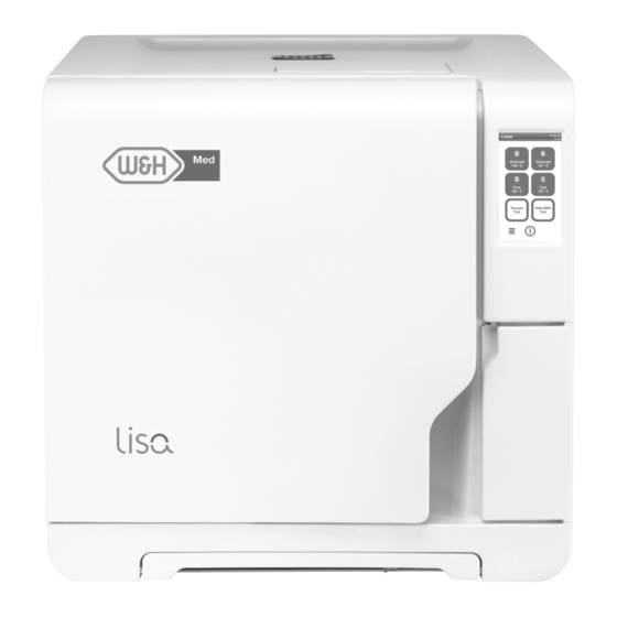
Getting started Product description FRONT VIEW Part Description Chamber door Tank filling cover-cap Water tank cover Touch screen Service door Sterilization chamber Dust filter Reset button of the thermostat switch Auxiliary cable loom Door gasket Door pin Lisa | Instructions for Use | VA131 Med ENG Rev08 | 20/10/2022 | © W&H Sterilization Srl... - Page 18 Getting started UPPER INTERNAL STRUCTURE Part Description Tank Water level sensor Water tank cover Internal tank cover Tank internal filters with metal cartridges Lisa | Instructions for Use | VA131 Med ENG Rev08 | 20/10/2022 | © W&H Sterilization Srl...
- Page 19 Getting started COMPONENTS BEHIND THE SERVICE DOOR Part Description Bacteriological filter Mains switch Identification label Used water drain connection (grey) Clean water drain connection (blue) Drain tube release button USB port Lisa | Instructions for Use | VA131 Med ENG Rev08 | 20/10/2022 | © W&H Sterilization Srl...
- Page 20 Getting started REAR VIEW Part Description USB and LAN ports Air gap cover Test connection Pressure safety valve cover Used water drain Water supply inlet Condenser grid Mains cable guide Mains cable plug socket Lisa | Instructions for Use | VA131 Med ENG Rev08 | 20/10/2022 | © W&H Sterilization Srl...
- Page 21 Getting started CHAMBER ACCESSORIES Part Description Tray Chamber rack: In the normal position, it can host 5 trays horizontally or 3 cassettes/containers vertically. In a 90° degrees rotated position, it can host 3 trays or 3 cassettes/containers horizontally. Lisa | Instructions for Use | VA131 Med ENG Rev08 | 20/10/2022 | © W&H Sterilization Srl...
-
Page 22: Installing The Sterilizer
Getting started Installing the sterilizer Clearance requirements to ensure proper air circulation: LOCATION REQUIREMENTS Notice: Do not place the sterilizer so that it is difficult to operate the controls behind the service door. Do not place the sterilizer so that it is difficult to disconnect the power supply plug. - Page 23 Getting started The electrical power supply of the sterilizer must fulfill all applicable LAN CONNECTION standards in the country of use, and must comply with the data label on the back of the sterilizer. WATER CONNECTIONS The sterilizer clean water tank can be filled manually by the user or automatically with a water supply system .
-
Page 24: Operating The Sterilizer
Getting started Operating the sterilizer INSTALLING THE STERILIZER WARNING! In case of sterilizer malfunctions immediately unplug the sterilizer and call for service. Do not attempt to POWER THE STERILIZER ON/OFF repair the sterilizer by yourself. Press the power switch behind the Notice: service door: once switched ON, the Please ensure that all installation requirements are met before... - Page 25 Getting started HOMEPAGE DESCRIPTION Part Description Title/purpose of the screen, or the cycle number and the current date and time. Available cycles. Available tests. Additional buttons used to navigate the menu. Lisa | Instructions for Use | VA131 Med ENG Rev08 | 20/10/2022 | © W&H Sterilization Srl...
-
Page 26: User Interface Menu
Getting started User interface menu SETTINGS MENU FUNCTIONS Icon Label Function MAIN MENU FUNCTIONS Device Opens the pages to set the device. Icon Label Function Menu Opens the menu. Language Sets device language. Cycle History Shows all the sterilization cycles. Date &... - Page 27 Getting started Icon Label Function Icon Label Function Cycle Exclusion IoDent Only if this service is supported in the country of use, Sets the cycles menu. and if the sterilizer is connected to it. Shows the status of the connection with the W&H monitoring server.
- Page 28 Getting started Icon Label Function Icon Function Label Guided Allows to start the configuration of: Change your PIN Changes the PIN code. language; Configuration code network connection; time zone settings; Options Administrator only. Permits the following: date & time settings; Identifies and saves the operator who starts sterilizer name.
- Page 29 Getting started MAINTENANCE MENU FUNCTIONS Icon Label Function Icon Label Function Local Printer Selects a printer connected to the sterilizer. Bact. Filter Shows the status of the consumables; Resets the cycle counter; Displays the consumable replacement procedure Shared Selects a printer connected to another sterilizer videos.
- Page 30 Getting started COMMON COMMANDS AND ICONS Icon Function Icon Function Icon Function Refreshes the page. Indicates that the option checked is working properly. Enters/exits the standby mode. Plays a video. Indicates the value that may be Starts a procedure. changed and appears by clicking on Moves to the previous/next screen.
- Page 31 Getting started Icon Function Indicates that the option is active/not active. Indicates that the option is enabled/disabled. Indicates that the user is using the administrator credentials. Gives information about the function displayed. Confirms the active option and saves a setting or a parameter. Copies the system info to the USB pen drive.
-
Page 32: Sterilizer Setup
Getting started Sterilizer setup SET THE DATE AND TIME To change the date and time format, current date and time zone: GUIDED CONFIGURATION On the homepage, tap > > > At the first start- up of the sterilizer, the Guided Configuration Tap the value you want to change (format, time, date and/or procedure automatically appears;... - Page 33 Getting started On the homepage, tap > > SET THE DISPLAY BRIGHTNESS To change the display brightness: If the connection is through the Ethernet cable, tap : the TCP/IP screen appears. On the homepage, tap > > > If the connection is through Wi-Fi dongle key, tap : after a to change the value.
-
Page 34: User Authentication
Getting started User authentication WHAT TO DO IF YOU FORGET YOUR PIN If... Then... PIN MANAGEMENT you are a common user contact the administrator PIN “0000” is assigned as default to each new user. It has to be you are the administrator contact your authorized service provider changed at the first login. -
Page 35: Usb Pen Drive
Getting started USB pen drive Standby mode DESCRIPTION DESCRIPTION A USB pen drive is available to be installed in order to automatically When in Standby mode, the sterilizer display remains dark and the record all the sterilization cycle reports. The USB pen drive can be sterilizer chamber is not heated to save energy. -
Page 36: Administrator
Administrator CONTENTS Enter the new user name and tap to confirm. This section deals with the following subjects: If desired, tap to give the administrator authority to the new user. User management Traceability options to confirm: the PIN of the new user is set to "0000" and Hide/Unhide a cycle a confirmation message appears. -
Page 37: Traceability Options
Administrator RESET A USER PIN SET THE TRACEABILITY OPTIONS On the homepage, tap > > On the homepage, tap > > Tap your user name. Tap your user name. Enter the PIN and tap to confirm. Enter your PIN and tap to confirm. - Page 38 Administrator HIDE/UNHIDE A CYCLE On the homepage tap > > > Tap your user name. Enter your PIN and tap to confirm. to hide a cycle from the homepage. to unhide a cycle from the homepage. to confirm and go back to the previous page. Lisa ...
-
Page 39: Managing Printers
Managing printers CONTENTS Label printer selection (optional) This section deals with the following subjects: FUNCTION AVAILABILITY Printer selection (optional) The first time you access the Label Printer ( ) menu, you will be Label printer selection (optional) requested to enter an activaction code. To require the activation Label printer usage (optional) code, please refer to the activation code instructions provided with Label content description... -
Page 40: Label Printer Usage (Optional)
Managing printers From the sterilizer from which the printer is not physically SELECT AND CALIBRATE A LOCAL LABEL PRINTER connected, tap homepage > > > On the homepage, tap > > : the local printer is located automatically. Tap the text box and enter the IP address previously noted. to center the printout properly in the label area. - Page 41 Managing printers printed only after the user has identified him/herself (with password DISABLE THE LABEL PRINTING if required) and the load has been checked and released, if these If the label printing is disabled, no label can be printed at the end of options have been enabled by the administrator.
-
Page 42: Label Content Description
Managing printers Label content description STRUCTURE Part Description Sterilizer model Serial number Software release Traceability code (alphanumerical and bar code) Depending on the traceability settings, this field may contain one of the Released following elements: the user who released the cycle the user who started the cycle the sterilizer ID Cycle... -
Page 43: Sterilizer Tests
Sterilizer tests CONTENTS This section deals with the following subjects: Sterilizer performance tests Bowie and Dick test Helix test Vacuum test Sterilizer performance tests TESTS THAT CAN BE PERFORMED ON THE STERILIZER Test Purpose Reference Bowie and Dick test Validate the sterilizer performance for textile load sterilization. See "Bowie and Dick test"... - Page 44 Sterilizer tests PURPOSE OF THE TEST The test is used to validate the sterilizer performance for textile load sterilization. DESCRIPTION It consists of several sheets of paper wrapped in a small packet with a chemical heat-sensitive indicator sheet in the middle. The colour assumed by this indicator sheet at the end of the sterilization cycle gives the result of the test.
- Page 45 Sterilizer tests On the homepage, tap Helix-B&D test. To set the duration of the Plateau/Sterilization phase and other settings, tap and enter your credentials if required: the chamber door locks. Wait until the end of the test and tap OPEN: the chamber door unlocks. Enter your credentials if required.
- Page 46 Sterilizer tests INTERPRET THE TEST RESULT Test Indicator What happened What to do next passed The entire surface of the indicator sheet has changed colour. Certain areas of the indicator sheet have not changed colour since there was an Repeat the test. If it fails air pocket during the cycle due to sterilizer malfunction.
-
Page 47: Helix Test
Sterilizer tests Helix test CAUTION! Follow local/national guidelines on the frequency of testing. PURPOSE OF THE TEST The test is used to validate the sterilizer performance for hollow items. DESCRIPTION It consists of a 1.5 m long tube open on one side and closed with a capsule containing a chemical indicator strip on the other side. The colour assumed by this indicator strip at the end of the sterilization cycle gives the result of the test. - Page 48 Sterilizer tests Place the tube with the capsule in the center of a tray in the lowest rack position and close the chamber door. On the homepage, tap Helix-B&D test. To set the duration of the Plateau/Sterilization phase and other settings, tap and enter your credentials if required: the chamber door locks.
-
Page 49: Vacuum Test
Sterilizer tests INTERPRET THE TEST RESULT Indicator What happened Test passed What to do next The indicator strip has turned dark. The air was completely removed from the capsule. Part of the chemical indicator strip has not turned dark. The air removal Repeat the test. - Page 50 Sterilizer tests CARRY OUT THE TEST Empty the sterilizer chamber to ensure no load is present. Close the chamber door and ensure the sterilizer chamber is completely dry and cold to avoid any false negative outcome. On the homepage, tap Vacuum test. and enter your credentials if required: the chamber door locks.
-
Page 51: Sterilization Cycles
Sterilization cycles CONTENTS CLEANING THE INSTRUMENTS This section deals with the following subjects: Clean all instruments thoroughly prior to sterilization. If possible, clean instruments immediately after use; always follow the Load maintenance and preparation instrument manufacturer ‘s instructions. Remove all traces of Prepare the sterilizer disinfectants and detergents. - Page 52 Sterilization cycles Follow these requirements: Load type Placement Items made from different On separate trays or wrapped/pouched Load type Placement materials (stainless steel, Hinged instruments (e.g., In open position carbon steel, aluminium, etc.) forceps, extraction pliers, etc.) Instruments manufactured Place paper among them and the trays to avoid Tubes Place tubes on a tray allowing the ends to from carbon steel...
-
Page 53: Prepare The Sterilizer
Sterilization cycles Prepare the sterilizer Turn the sterilizer ON: after the initialization the homepage appears. WARNINGS GENERAL RECOMMENDATIONS Notice: use only distilled or demineralized water (see "Feed water Follow these recommendations to obtain the most from the drying: specifications (EN 13060)" on page 115 for technical requirements). Ensure the paper side of the sterilization bags faces up, and Do not add any chemical / additive to the water. -
Page 54: Sterilization Cycle Management
Sterilization cycles Sterilization cycle management AVAILABLE ECO DRY MODES Icon Mode Description ECO DRY The drying time is automatically adjusted to the shortest plus possible for the total amount of load: the smaller the load, RUN A STERILIZATION CYCLE IMMEDIATELY the faster the cycle. - Page 55 Sterilization cycles The sterilization is completed. Tap to view the cycle To change the start time, tap Start cycle at. summary or tap to view the cycle information. See "View the Tap the time or the date: a settings page opens. cycle parameters"...
- Page 56 Sterilization cycles To program the sterilizer proceed as follows: SET THE DRYING TIME For each ECO DRY mode, the drying time is automatically adjusted to Load the chamber and close the chamber door. the total amount of load and cannot be modified. To set a new drying time for the program, you should disabled the ECO DRY mode first.
- Page 57 Sterilization cycles VIEW THE CYCLE PARAMETERS END OF A STERILIZATION CYCLE You can check the real time cycle parameters or the cycle At the end of the S Fast 134 cycle, the sterilizer could perform two parameters at the end of the cycle. Following is an example: drainage periods of about 30 seconds each and the message "Draining"...
-
Page 58: Unloading
Sterilization cycles Note: water could be present in the chamber when opening the door. To STOP A STERILIZATION CYCLE prevent spilling place a towel below the chamber door. WARNING! You can stop the cycle at any time. Instruments must not be considered sterile if this occurs before the MESSAGES OF A STOPPED STERILIZATION CYCLE DRY phase. - Page 59 Sterilization cycles STORED REPORT FORMAT PRINT OR SAVE A CYCLE REPORT ON THE USB PEN DRIVE The summarized reports are stored in HTML format and the analytical On the homepage, tap > > reports in SCL format. All parameters are recorded every second. Scroll the list and tap the desired sterilization cycle: the report WHAT HAPPENS WITH UNSAVED CYCLES opens.
- Page 60 Sterilization cycles SAVE ALL THE CYCLE REPORTS ON THE USB PEN DRIVE SET THE REMOTE FOLDER FOR SAVING THE REPORTS The number of reports that can be saved on the USB pen drive To activate the remote storage and set the necessary parameters do depends upon the USB capacity.
- Page 61 Sterilization cycles TEST THE DATA STORAGE Note: the test function is available only if the remote data storage is enabled. See "Set the remote folder for saving the reports" on the previous page. On the homepage, tap > > : a sequence of tests is automatically performed. In case a test fails, check the relevant settings and tap repeat the test sequence, if the error persists call your IT manager.
- Page 62 Sterilization cycles CYCLE REPORT STRUCTURE Data Description Following the structure of a cycle report: Sterilizer model Sterilizer serial number Software rev. Software revision number Sterilizer Name Surgery – practice – doctor name Cycle Name of the executed cycle Number Cycle counter Sterilizat.
- Page 63 Sterilization cycles Data Description Cycle end conditions Cycle water consumption F0 value Cycle time Cycle time Date(below) Cycle end date and time "Cycle completed" Cycle outcome Trk. Tracking code for traceability management Lisa | Instructions for Use | VA131 Med ENG Rev08 | 20/10/2022 | © W&H Sterilization Srl...
-
Page 64: Maintenance
Maintenance CONTENTS Warnings for maintenance operations This section deals with the following subjects: WARNINGS Warnings for maintenance operations Ordinary maintenance WARNING! Turn the sterilizer OFF and remove the power cord before beginning any maintenance. Follow all health, Monthly or 50-cycle maintenance safety, cross-infection and cross-contamination 400-cycle maintenance protocols. -
Page 65: Ordinary Maintenance
Maintenance Ordinary maintenance damaged, or if the filters are clogged or discolored. EXPIRED MAINTENANCE MAINTENANCE BY THE USER A video animation is available on https://video.wh.com/en_ global/dental-faq. Frequency Cycles Operation The sterilizer monitors the wear of consumables by counting the Cleaning the door gasket and the chamber face Monthly side. - Page 66 Maintenance REPLACE THE CONSUMABLE BEFORE THE MAINTENANCE DUE DATE If you replace the consumables before the request of replacement appears, you should manually reset the counters through the following procedure. On the homepage, tap > Select the consumable you want to replace: a message appears showing the current worked hours of the part.
-
Page 67: Monthly Or 50-Cycle Maintenance
Maintenance Monthly or 50-cycle maintenance CLEANING THE DOOR GASKET AND THE CHAMBER FACE SIDE Proceed as follows: Clean the gasket seat and the chamber face side with a damp, lint-free cloth moistened with clean water. Notice: Do not use abrasive products, cutting tools or sharp objects. Rinse with clean water. - Page 68 Maintenance CLEANING THE CHAMBER AND THE CHAMBER ACCESSORIES Proceed as follows: Remove the trays and the chamber rack. Clean the chamber with a damp sponge and a mild detergent solution paying attention not to bend or damage the temperature probe inside the sterilizer chamber. Rinse with water.
- Page 69 Maintenance CLEANING THE CHAMBER FILTER Proceed as follows: Allow the sterilization chamber to cool down. Empty the sterilizer chamber by removing the trays and the rack. Turn the filter cap at the back of the chamber (bottom/center) counter-clockwise. Lisa | Instructions for Use | VA131 Med ENG Rev08 | 20/10/2022 | © W&H Sterilization Srl...
- Page 70 Maintenance Remove the filter cap and the cartridge filter. Rinse the cartridge filter with tap water. Insert the cartridge filter in the filter cap. Insert the filter cap with the cartridge filter in its original position. Lisa | Instructions for Use | VA131 Med ENG Rev08 | 20/10/2022 | © W&H Sterilization Srl...
- Page 71 Maintenance Lock the filter cap by turning it clockwise. CLEANING THE EXTERNAL SURFACES OF THE STERILIZER Proceed as follows: Clean all external sterilizer covers with a slightly damp cloth moistened with water. For better cleaning results, clean with W&H MC-1000 cleaning solution. Notice: never use any other disinfectant, detergent or abrasive product, as they might result aggressive for the external covers and damage them.
-
Page 72: 400-Cycle Maintenance
Maintenance 400-cycle maintenance REPLACING THE BACTERIOLOGICAL FILTER A video animation is available on https://video.wh.com/en_global/dental-faq. Notice: if you replace this consumable before the maintenance due date you have to reset the cycle counter. See "Replace the consumable before the maintenance due date" on page 66. Proceed as follows: Open the service door. - Page 73 Maintenance REPLACING THE DUST FILTER A video animation is available on https://video.wh.com/en_global/dental-faq. Notice: if you replace this consumable before the maintenance due date you have to reset the cycle counter. See "Replace the consumable before the maintenance due date" on page 66. Proceed as follows: Pull out the dust filter handle from underneath the sterilizer.
- Page 74 Maintenance Lift the used filter from the handle and remove it. Insert the new filter into the handle. Lisa | Instructions for Use | VA131 Med ENG Rev08 | 20/10/2022 | © W&H Sterilization Srl...
- Page 75 Maintenance Slide the handle back into its original position. Lisa | Instructions for Use | VA131 Med ENG Rev08 | 20/10/2022 | © W&H Sterilization Srl...
-
Page 76: 800-Cycle Or Biannual Maintenance
Maintenance 800-cycle or biannual maintenance SEQUENCE OF PROCEDURES TO CLEAN THE WATER TANKS To clean the water tanks, proceed as follows: "Prepare the sterilizer for cleaning the water tanks" on the next page. "Access to the water tanks" on page 78. "Clean the water tanks"... - Page 77 Maintenance PREPARE THE STERILIZER FOR CLEANING THE WATER TANKS A video animation is available on https://video.wh.com/en_global/dental-faq. Proceed as follows: Switch OFF the sterilizer and disconnect the mains cable. Completely drain both water tanks (see "Draining the used and clean water tank" on page ...
- Page 78 Maintenance ACCESS TO THE WATER TANKS A video animation is available on https://video.wh.com/en_global/dental-faq. Proceed as follows: Lift the water tank cover. Lisa | Instructions for Use | VA131 Med ENG Rev08 | 20/10/2022 | © W&H Sterilization Srl...
- Page 79 Maintenance Remove the internal tank cover. Clean and dry the internal tank cover and its rubber membrane to eliminate any condensate. Notice: never use disinfectants, strong detergents or abrasive products. Use a slightly damp cloth moistened with water. Lisa | Instructions for Use | VA131 Med ENG Rev08 | 20/10/2022 | © W&H Sterilization Srl...
- Page 80 Maintenance CLEAN THE WATER TANKS A video animation is available on https://video.wh.com/en_global/dental-faq. Notice: Do not touch the water level sensors. If misplaced or misaligned from their original position, the operation of the sterilizer could be impaired. Proceed as follows: Clean the internal tank surfaces with a soft sponge moistened with water. For better cleaning results, clean with W&H MC-1000 cleaning solution.
- Page 81 Maintenance Remove the internal filters. Clean the metal cartridges of the internal filters with tap water. Reposition the internal filters. Lisa | Instructions for Use | VA131 Med ENG Rev08 | 20/10/2022 | © W&H Sterilization Srl...
- Page 82 Maintenance Reposition the internal tank cover and then the water tank cover. Detach the drain tube. Lisa | Instructions for Use | VA131 Med ENG Rev08 | 20/10/2022 | © W&H Sterilization Srl...
-
Page 83: 800-Cycle Maintenance
Maintenance 800-cycle maintenance REPLACING THE DOOR GASKET A video animation is available on https://video.wh.com/en_global/dental-faq. Notice: if you replace this consumable before the maintenance due date you have to reset the cycle counter. See "Replace the consumable before the maintenance due date" on page 66. Proceed as follows: Fully open the chamber door. - Page 84 Maintenance Insert the new seal and press first up and down. Press left and right and then the entire seal circumference to ensure its perfect placement. Notice: a steam discharge can damage the sterilizer plastic parts. Ensure the seal does not stick out. Wipe any residual water and run a Vacuum and Helix test to check for perfect tightness of the seal.
-
Page 85: 4000 Cycle Or Five-Year Maintenance
Maintenance 4000 cycle or five-year maintenance Element Replace Clean Check Internal parts, with particular care for the condenser fins and the main board GENERAL CHECK AND SERVICE REQUIRED Notice: regular service is imperative to ensure continuous and Pneumatic connections effective operation of the sterilizer. Electrical connections A general check and service should be carried out every 4000 cycles Temperature and pressure calibration... -
Page 86: Extraordinary Maintenance
Maintenance Extraordinary maintenance DRAINING THE USED AND CLEAN WATER TANK If you left accidentally the tanks full for more than seven days or if you plan not to use the sterilizer for at least seven days, you have to drain the tanks. -
Page 87: Disposal
Maintenance Disposal DISPOSAL RESPONSIBILITY Separate the various components according to the materials they are made of Drop the sterilizer with a company that specializes on the recycling of related products Do not abandon the sterilizer in unsecured places Always refer to current/applicable laws and rules in the country of use The same instructions apply to disposal of all used consumable parts. -
Page 88: Diagnostics
Diagnostics CONTENTS This section deals with the following subjects: Errors Troubleshooting Emergency door opening Errors CHECKS AND ACTIONS Notice: for any error not listed in this table, call technical service. Code Description Actions Load cannot be considered sterile. See "End of a sterilization cycle" on page 57 Repeat the cycle. - Page 89 Diagnostics Code Description Actions Wait before opening the chamber door. Allow the sterilization chamber to cool down. See error "13x to 16x" Repeat the cycle. below. If the problem persists, call service. 13x to 16x Check water level in the clean water tank. Reset the safety thermostat.. Repeat the cycle.
- Page 90 Diagnostics Code Description Actions Check the door gasket. Clean or replace it if necessary. Repeat the cycle. If the problem persists, call service. Clean the chamber face side. Clean the chamber filter. Check if chamber filter is properly locked in the cap. Check the load does not exceed the MAXIMUM WEIGHT LIMITS.
- Page 91 Diagnostics MESSAGES AND ALERTS Notice: for any error not listed in this table, call technical service. Message/Alert Description Action Fill clean water tank. There is not enough water in the tank to perform a Fill the water tank as requested. cycle.
- Page 92 Diagnostics Message/Alert Description Action Door Gasket replacement is due. These messages advise that one consumable must Replace the consumable and tap to reset the counter (See "Maintenance" on be replaced. page 64). Have you replaced the door gasket? If you don't replace the consumable, press In this case, you may still use the sterilizer but the message will appear again after Bact.
-
Page 93: Troubleshooting
Diagnostics Troubleshooting ERROR PAGE During the sterilization cycle, the sterilizer is continuously monitored by a control system. If an anomaly is detected, the cycle is aborted MANAGING ERRORS automatically, and the sterilizer starts a reset phase. If during a sterilization cycle an error occurs do the following: The following page appears: Wait until the end of the reset phase. - Page 94 Diagnostics RESET THE SAFETY THERMOSTAT The sterilizer is fitted with a safety thermostat to prevent it from overheating. If the safety thermostat operates because of too high temperatures, the error 240 or a timeout error is displayed. The thermostat must be reset manually. Proceed as follows: Switch the sterilizer OFF and remove the mains cable.
- Page 95 Diagnostics Remove the dust filter and move the sterilizer closer to the shelf edge. Push the reset button of the thermostat switch: a click sound indicates that the thermostat switch has been reset. Lisa | Instructions for Use | VA131 Med ENG Rev08 | 20/10/2022 | © W&H Sterilization Srl...
- Page 96 Diagnostics Insert the dust filter back into its original position. Connect the mains cable and place the sterilizer back into its original position. Switch the sterilizer ON. Wait for the sterilizer to finish the error reset phase and follow the instructions on the display.
- Page 97 Diagnostics TROUBLESHOOTING TABLE Note: if your problem is not resolved, call your authorized service provider. Notice: before sending the sterilizer for technical service, remove the mains cable, empty both water tanks and use the original or appropriate packaging. Problem Possible cause Solutions The sterilizer remains switched The mains switch or network circuit breaker is OFF.
- Page 98 Diagnostics Problem Possible cause Solutions Corrosion or spots on Tap water on instruments when placed in the Ensure that instruments are dry before they are placed in the sterilizer. instruments. sterilizer. Use of water of poor quality or water containing Drain both water tanks.
- Page 99 Diagnostics Problem Possible cause Solutions When the sterilizer is connected Water fill system not connected. Connect the water fill system to the sterilizer. See "Water quality" on page 115 to an automated water supply When the water fill system attempted to fill the Since water tank filling is attempted only once in-between cycle execution, this event system: there is no clean water in tank, water was temporarily unavailable.
-
Page 100: Emergency Door Opening
Diagnostics Emergency door opening WARNING ABOUT OPENING THE DOOR IN EMERGENCY WARNING! High pressure. Risk of explosion, jet of hot steam, sudden opening of the door. Carry out the following procedure only if necessary and only when NO RESIDUAL PRESSURE IS IN THE CHAMBER. Any attempt to open the door while the unit is still hot or under pressure could expose the operator and the surrounding personnel to serious risk. - Page 101 Diagnostics Extract the dust filter and remove the auxiliary cable loom. Firmly open the service door. Unscrew the bacteriological filter by hand (counter-clockwise). Lisa | Instructions for Use | VA131 Med ENG Rev08 | 20/10/2022 | © W&H Sterilization Srl...
- Page 102 Diagnostics Plug two batteries into the connectors. Holding the service door pulled, plug the plastic connector into the socket behind the bacteriological filter. As soon as the door opens, unplug the plastic connector to prevent system overload and consequent damage. Put the auxiliary cable loom back in the dust filter handle and insert the dust filter in the sterilizer.
-
Page 103: Technical Data
Technical data CONTENTS This section deals with the following subjects: Sterilization cycles Sterilization cycle phases Technical data Recommendations for validation Diagrams Water quality Accessories, spare parts, consumables Authorized W&H service partners Sterilization cycles WARNINGS For your safety and for the safety of your patients: WARNING! Never process objects different from those specified in the cycle program table and never exceed the maximum load weight limits specified in it as this could impair the sterilization process. - Page 104 Technical data STANDARD STERILIZATION CYCLES AVAILABLE There are four sterilization cycles available, all of them complying with the European Standard EN13060: three B-type cycles one S-type cycle Cycle Cycle name Purpose type B Universal 134 For all your general items like hand instruments, forceps, etc. Features an extended sterilization time, if this is required for your load or mandated in your country.
- Page 105 Technical data COMMON STERILIZATION CYCLE DATA Sterilization cycles B Universal 134 B Prion / Extended 134 * B Universal 121 S Fast 134 134 °C (273 °F) 134 °C (273 °F) 121 °C (250 °F) 134 °C (273 °F ) Sterilization temperature 3.03 bar 3.03 bar...
- Page 106 Technical data TOTAL CYCLE DURATION The total cycle time includes the drying time and may vary according to different elements, such as the following: type of load (solid or porous) load weight duration of the drying phase (if the ECO DRY mode is disabled) other factors Load Empty...
- Page 107 Technical data MAXIMUM LOAD FOR INSTRUMENTS Note: the load given includes the trays, the containers and everything is put into the chamber, with the sole exclusion of the tray rack. Instruments Bagged Unwrapped Porous Lisa 17 Lisa 22 Lisa 17 Lisa 22 Lisa 17 Lisa 22...
-
Page 108: Sterilization Cycle Phases
Technical data Sterilization cycle phases COMMON LEGEND OF THE STERILIZATION CYCLE PHASES Following is the description of the sterilization phases. Code Description Pre-heating of the sterilizer. This phase is not considered a part of the cycle. PV1 - PV3 Vacuum pulse (removal of air from the sterilizer chamber/load). PV1 - PV6 PP1 - PP2 Pressure pulse (steam generation). - Page 109 Technical data B-TYPE STERILIZATION CYCLE PHASES All B-type sterilization cycles feature the same basic pressure profile as shown in the graph below. The duration and the temperature of the sterilization phase differ between the various cycles. Lisa | Instructions for Use | VA131 Med ENG Rev08 | 20/10/2022 | © W&H Sterilization Srl...
- Page 110 Technical data S-TYPE STERILIZATION CYCLE PHASES The S Fast 134 cycle is specifically designed to sterilize unwrapped instruments, for immediate use on patients, not requiring a complete drying. Thus, the drying phase of this cycle is short, making this cycle the fastest available. Lisa ...
-
Page 111: Technical Data
Technical data Technical data INSTALLATION REQUIREMENTS From +5 °C to +40 °C (from +41 °F to +104 °F) Working temperature Working relative humidity Max. RH 80% up to 31 °C (88 °F), linearly decreasing to 50% at 40 WATER SUPPLY SYSTEM °C (104 °F) Temperature max. - Page 112 Technical data STERILIZER CHAMBER 2.6 bar (37.7 psi) Pressure safety valve Safety thermostats 180 °C (356 °F) Total volume Lisa 17 - 17 l/Ø: 250 mm/D: 362 mm (4.5 gal , Ø: 9.8’’/D: 14’’) Lisa 22 - 22 l/Ø: 250 mm/D: 440 mm (5.8 gal , Ø: 9.8’’/D: 17’’) Usable space * Lisa 17 - W: 190 mm/H: 190 mm/D: 310 mm (W: 7.5’’/H: 7.5’’/D:...
-
Page 113: Recommendations For Validation
Technical data Recommendations for validation TEST VALIDATION POINTS Lisa sterilizers can be validated in accordance to EN ISO 17665-1. For further details please refer to the Qualification/Validation guide for sterilization cycles of the manufacturer. Part Description Hottest points Coldest points Lisa ... -
Page 114: Diagrams
Technical data Diagrams CONNECTION DIAGRAMS Data communication Water system (*): the water filtration system must be fitted with a backflow preventing device complying to national and local regulations. For water requirements see "Technical data" on page 111. Lisa | Instructions for Use | VA131 Med ENG Rev08 | 20/10/2022 | © W&H Sterilization Srl... -
Page 115: Water Quality
Technical data Water quality Contaminants/minerals/qualities Value/Specification Hardness < 0.02 mmol/l FEED WATER SPECIFICATIONS (EN 13060) No chemicals or additives must be added Chemical additives Notice: do not use rust inhibitor or any other agents in the clean to the water used for the steam water tank. -
Page 116: Accessories, Spare Parts, Consumables
Technical data Accessories, spare parts, consumables Picture Part Part number Standard chamber rack for 5 F523032X aluminium trays for Lisa 22 Note: use only accessories, spare parts and consumables recommended by W&H. Usable space - Tray size (mm): 190 x 21 x 387 Note: before purchasing, check that the accessories fulfill all applicable 190 x 28 x 387 standards in the country of use. - Page 117 Technical data Picture Part Part number Picture Part Part number Optional chamber rack for 4 F523012X Optional chamber rack for 3 F523020X cassettes / containers for Lisa cassettes / containers for Lisa Usable space - Cassette size Usable space - Tray size (mm): 205 x 36 x 300 (mm): 210 x 36 x 300...
- Page 118 Technical data Picture Part Part number Picture Part Part number Optional chamber rack for 6 F523034X Optional chamber rack for 2 F523035X aluminium trays for Lisa 22 aluminium trays and 3 wider aluminium trays for Lisa 22 Usable space - Tray size (mm): 190 x 15 x 387 Usable space - Tray size (mm): 190 x 22 x 387...
- Page 119 Technical data Picture Part Part number Picture Part Part number Optional chamber rack for 6 F523041X Drain tube kit with fittings A812110X aluminium trays for Lisa 22 Usable space - Tray size (mm): 190 x 15 x 387 Drain tube S230900X 190 x 22 x 387 190 x 22 x 387...
-
Page 120: Authorized W&H Service Partners
Technical data *: the rack, rotated 90°, accepts 5 standard aluminium trays. Picture Part Part number Label printer (label printer only) 19721109 CONSUMABLES Label printer USB connection kit 19721123 Picture Part Part number When replace it USB connection cable 1 roll of 2100 labels Bacteriological filter W322400X Every 400 cycles... -
Page 121: Documentation Forms
Documentation forms CONTENTS Question Answer This section deals with the following subjects: Completeness of the Instructions for Use W&H installation check-list Were all sections of the Instructions for Use of the sterilizer covered and explained during the in-service? Helix test documentation form Workplace suitability Is the allocated countertop for the sterilizer levelled and flat? Yes W&H installation check-list... - Page 122 Documentation forms Question Answer Question Answer Have you shown the Head of the clinic/practice how to Check manually abort a cycle? Have you executed a Vacuum test? Have you shown the Head of the clinic/practice the Have you executed a B Universal 134 cycle program with the maintenance program and procedures? tray rack and trays inserted? Have you shown the Head of the clinic/practice how to use...
- Page 123 Documentation forms ADDRESSES FOR SENDING THE INSTALLATION CHECK-LIST Send a copy of the installation check-list duly filled-in to both of the following addresses: +43 6274 6236-55 Fax: Ignaz-Glaser-Straße 53, Postfach 1 Mail 5111 Bürmoos Austria Lisa | Instructions for Use | VA131 Med ENG Rev08 | 20/10/2022 | © W&H Sterilization Srl...
-
Page 124: Helix Test Documentation Form
Documentation forms Helix test documentation form INSTRUCTIONS Use this page to create a logbook tracing the effectiveness of the sterilization cycle during the whole lifespan of your sterilizer. FORM Date Cycle n. Operator Released Signature Chemical indicator Lisa | Instructions for Use | VA131 Med ENG Rev08 | 20/10/2022 | © W&H Sterilization Srl... - Page 125 Documentation forms Date Cycle n. Operator Released Signature Chemical indicator Lisa | Instructions for Use | VA131 Med ENG Rev08 | 20/10/2022 | © W&H Sterilization Srl...
- Page 126 Documentation forms Date Cycle n. Operator Released Signature Chemical indicator Lisa | Instructions for Use | VA131 Med ENG Rev08 | 20/10/2022 | © W&H Sterilization Srl...
- Page 128 VA131 Med W&H Sterilization Srl Instructions for Use via Bolgara, 2 Brusaporto (BG) Rev08 Italy 20/10/2022 med.wh.com Subject to changes +39 035 66 63 000...
Need help?
Do you have a question about the Lisa VA131-17 and is the answer not in the manual?
Questions and answers