Advertisement
Technische Alternative RT GmbH
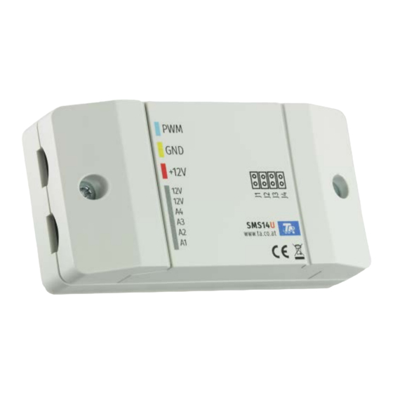
The stepper motor controller SMS14 is used for the control of unipolar and bipolar motors.
Through adjustment of the jumpers (J1-J4), the following settings can be made.
not set
J1
set
not set
J2
set
not set
J3
set
not set
J4
set
Jumpers J1-J4 on the PCB
The positions of the jumpers are only read once as the device boots (= when supplying it with power).
If the jumpers are adjusted during operation, their positions will only be updated if the device is re-
started.
A-3872 Amaliendorf, Langestraße 124
Tel +43 (0)2862 53635
Stepper motor controller
Control of a unipolar step motor in half step mode (8 states)
Control of a bipolar step motor with single-phase full step (4 states)
500 steps
1000 steps
30% holding current, when target position is reached
no holding current
Reference Drive sets Closed state, 0% means Closed
Reference drive sets Open state, 0% means Open
mail@ta.co.at
1
SMS14U
SMS14B
Vers. 2.01
J1 J2
J4
J3
Advertisement
Table of Contents

Related Manuals for TA SMS14U

Summary of Contents for TA SMS14U
- Page 1 Technische Alternative RT GmbH SMS14U SMS14B A-3872 Amaliendorf, Langestraße 124 Tel +43 (0)2862 53635 mail@ta.co.at Vers. 2.01 Stepper motor controller The stepper motor controller SMS14 is used for the control of unipolar and bipolar motors. Through adjustment of the jumpers (J1-J4), the following settings can be made.
- Page 2 Reference drive The SMS14 detects the position of the step motor via a reference drive. The step motor will be closed or opened completely, and the SMS14 gains its orientation via the reference drive. If Jumper J4 is set, the SMS14 opens the step motor completely, and defines the position “0%” as the step motor being completely open.
- Page 3 Depending on the model of the motor, it is connected using 4 or 6 terminals. SMS14B (4 poles, bipolar) SMS14U (6 poles, unipolar) Super-capacitors (optional) 3 super-capacitors can be connected on the right side of the module. These serve as emergency power supply, allowing for the valve to the opened or closed during a power outage.
- Page 4 Technical data 12 step motor injection valves (unipolar or bipolar, defined by Suitable for jumper setting J1) min. coil resistance >30 Ω max. coil current <400 mA Suitable super-capacitors (not 3 x 5F at 5-6V included) Subject to technical modifications as well as typographical and printing errors. This manual is only valid for devices with the corresponding firmware version.
Need help?
Do you have a question about the SMS14U and is the answer not in the manual?
Questions and answers