
Related Manuals for Propox EVBsam7s


Summary of Contents for Propox EVBsam7s
- Page 1 Evaluation Board for MMsam7s minimodule User Guide REV 0.8 Many ideas one solution...
-
Page 2: Table Of Contents
Contents 1 INTRODUCTION ............................3 ..............................3 EATURES THE BOARD............................4 ....................4 LACEMENT OF ELEMENTS ON THE BOARD ........................5 RRANGEMENT OF LEAD OUTS ..........................5 OARD CONFIGURATION ............................7 OARD SUPPLY ..............................7 DIODES ............................8 BUTTONS ............................... 8 DISPLAY ............................ -
Page 3: Introduction
Introduction The EVBlpc213x board was created with the aim of providing a hardware base for a designer of systems relying on the MMlpc213x minimodule, allowing to realize and verify quickly one’s own ideas. Having this in mind, the board has been designed in such a way that the user has access to all terminals of the module which are led out to connectors. -
Page 4: The Board
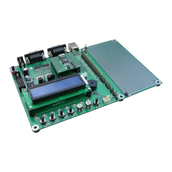
2 The Board Placement of elements on the board Figure 1 Placement of elements on the EVBlpc213x board. 1. Prototype area 2. Connector with led-out MMlpc213x module terminals 3. USB connector 4. RS232 0 connector 5. RS232 1 connector 6. Supply connector 7. -
Page 5: Arrangement Of Lead-Outs
Arrangement of lead-outs Name Name Function in MMsam7s Function in MMsam7s USBDP USBDN PA31 DataFlash – #CS PA30 PA29 #RESET PA28 PA27 UDP_PUP ADVREF PA17 PA18 PA21 PA19 PA22 PA23 PA20 PA16 PA15 PA14 PA13 DataFlash – SCK DataFlash - MOSI PA24 PA25 PA26... - Page 6 Figure 2 Placement of configuration jumpers. Jumpers description: Default Description setting +5V supply voltage for MMlpc213x minimodule. JP11 Closed This jumper allows measurement of current drawn by minimodule. During normal operation this jumper should be closed. Opened Board +5V power supply from USB bus. More details in “USB interfaced section”. Opened Jumpers connecting RxD (JP2), TxD (JP3), RTS (JP4) and CTS (JP5) lines of Opened...
-
Page 7: Board Supply
Board supply The EVBlpc213x board can be supplied in two ways: • From an external power supply with an output of 7-12 V AC or 9-15 V DC, having a standard plug with a bolt diameter of 2.1 mm, connected to supply socket J3. In case of a DC supply voltage its polarity is irrelevant. -
Page 8: Push-Buttons
+3.3V R15 470R LED0 LEDn R14 470R LED1 R13 470R LED2 R12 470R LED3 R11 470R LED4 R10 470R LED5 R9 470R LED6 R8 470R LED7 Figure 5 Implementation of LED diodes. Push-buttons The EVBlpc213x board is equipped with four microswitches which can be connected to any lead of the microcontroller. -
Page 9: Potentiometers
LCD_RS LCD_RW LCD_E CONTRAST 100n LCD 2x16 Figure 7 Default LCD configuration BC 817 – backlight permanently turned on, contrast regulated with R5 potentiometer. Figure 8 Connection of LCD display on the board.. Potentiometers EVBlpc213x has two potentiometers, POT0 and POT1. The potentiometers can be used to simulate the outputs of analog circuits. -
Page 10: Reset Button
RESET button The EVBlpc213x board is equipped with an on-board resetting button; by pressing it we force a low state on the RESET terminal of the module. #RESET RESET Figure 11 Implementation of the RESET push-button. RS-232 interfaces EVBlpc213x has two RS232 ports with DB-9 connector. TxD and RxD lines are led to jumpers through MAX3232 transceiver. -
Page 11: Usb Interface
USB interface Board is equipped with USB interface connector. USB allows connection with PC or other USB host and transfer data with up to 1MB/s speed. Along with USB connector there are RC filtering circuits and jumper for connecting USB bus power with board +5V voltage. 100n USBDN USBDP... -
Page 12: 1-Wire Interface
Pull-up is by default turned on by R13 resistor. Active reset signal or low level on UDP_PUP line turns off pull- up, what is interpreted by USB host as disconnection of USB device. 1-Wire interface The EVBlpc213x board has a 1-Wire bus connector. This connector can be used to connect e.g. a digital DS1820 thermometer or Dallas/Maxim iButton reader from. -
Page 13: Technical Assistance
19 20 Header 10X2 Figure 19 Connection of JTAG socket on EVBlpc213x. JTAG programmer/debugger may be found on page: - ARMCable I: http://www.propox.com/products/t_122.html 3 Technical assistance In order to obtain technical assistance please contact support@propox.com . In the request please include the following information: •... -
Page 14: Board Layout And Dimensions
5 Board layout and dimensions 6 Schematic... - Page 15 15 16 #RESET 100n DBGRQ 17 18 DBGACK 19 20 DB9F Header 10X2 RESET RB152 1N4148 POWER Vout 7805 http://www.propox.com email: support@propox.com 470u/25V 100n 100n 47u/16V +3.3V 470R Title: EVBsam7s +3.3V Rev: Size: File: Sheet 1 of 1 1.00 Date: 9-05-2005...
Need help?
Do you have a question about the EVBsam7s and is the answer not in the manual?
Questions and answers