Table of Contents
Advertisement
Advertisement
Table of Contents

Subscribe to Our Youtube Channel
Related Manuals for Volvo EWR150E


Summary of Contents for Volvo EWR150E
- Page 1 EWR150E Ref. no. PUB20045551-B English 2015.10 Volvo, Konz...
- Page 2 California Proposition 65 Warning Diesel engine exhaust and some of its constituents are known to the State of California to cause cancer, birth defects, and other reproductive harm. California Proposition 65 Warning Battery posts, terminals and other related accessories contain lead and lead compounds, chemicals known to the State of California to cause cancer and other reproductive harm.
- Page 3 Safety when servicing Maintenance Maintenance Specifications Specifications Alphabetical index Alphabetical index Ref. No. 20045551-B The original language is English. Original instructions. 2015.10 Copyright © 2015, Volvo Construction Equipment. All rights reserved. Copyright © 2015, Volvo Construction Equipment. All rights reserved.
- Page 4 Foreword Foreword Safety regulations Safety regulations The machine operator is responsible for being aware of and complying with the relevant, legally prescribed, national and regional safety instructions. The safety instructions in this operator's manual are applicable only in cases where no legislated safety instructions are in force.
-
Page 5: Table Of Contents
Table of contents Table of contents Table of contents Table of contents Foreword Foreword ..............1 ..............1 Identification numbers ............6 Presentation Presentation ............7 ............7 Machine view ..............12 CE-marking, EMC-directive ..........13 Communication equipment, installation ......16 Safety components ............ - Page 6 Table of contents Table of contents Safety when servicing .......... Safety when servicing .......... 214 Service position ............... 215 Before service, read ............218 Entering, leaving and climbing the machine ....221 Fire prevention ..............223 Handling hazardous materials ......... 225 Handling line, tubes and hoses ........
-
Page 8: Identification Numbers
Make a note below of the identification numbers of the machine and its components. Always state the number when contacting the manufacturer and when ordering spare parts. Manufacturer: Manufacturer: Volvo Construction Equipment Germany GmbH D-54329 Konz-Könen Germany Machine PIN (Serial number) - Page 9 AdBlue®/DEF. For distribution of AdBlue®/DEF (only valid for US market): For distribution of AdBlue®/DEF (only valid for US market): - Volvo CE Customer Support: 1-877-823-1111 (business Volvo CE Customer Support: 1-877-823-1111 (business hours) hours) - www.volvoce.com (outside of business hours)
- Page 10 Presentation Presentation For distribution of AdBlue®/DEF (all other markets), please For distribution of AdBlue®/DEF (all other markets), please contact your local Volvo dealer for more information. contact your local Volvo dealer for more information. See page See page 268 for information about filling AdBlue®/DEF.
- Page 11 Examples of optional equipment: trailer towing solution (TTS), boom suspension system (BSS), tiltrotator control system, different types of attachment brackets, deluxe operator seat, additional working lights, sun blind, mudguards and much more. Please contact Volvo distributors for further information about optional equipment.
- Page 12 The machine is equipped with a software system, which records various information about the machine and this information is transferred from the machine to Volvo and used by Volvo and its authorized workshops in the product development process and for possible malfunction detection.
- Page 13 Presentation Presentation The CareTrack system transmits data, in the same way a mobile phone does, with a maximum output rate of 10 W. The transmitter is always on and the operator cannot switch it off. Local precautions and restrictions applicable to mobile phones, for example safety distance, also apply to the CareTrack system.
-
Page 14: Machine View
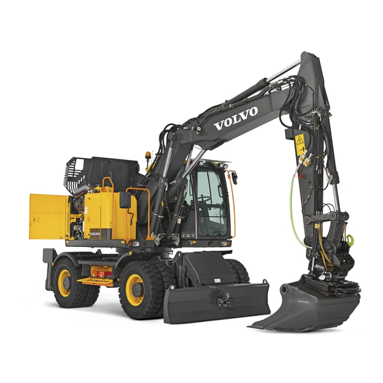
Presentation Presentation Machine view Machine view Machine view Machine view V1160039 EWR150E with two-piece boom AdBlue®/DEF tank Attachment quick coupler (between dipper arm and bucket) Fuel Tank Bucket Hydraulic oil tank Boom cylinders Side cover Stabiliser legs Counterweight Side cover... -
Page 15: Ce-Marking, Emc-Directive
As proof that the requirements are met, the machine is supplied with an EU Declaration of Conformity, issued by Volvo CE for each separate machine. This EU declaration also covers attachments manufactured by Volvo CE. The documentation is a valuable document, which should be kept safe and retained for at least ten years. - Page 16 Presentation Presentation CE-marking, EMC-directive CE-marking, EMC-directive EU EMC Directive EU EMC Directive The electronic equipment of the machine may in some cases cause interference to other electronic equipment, or suffer from external electromagnetic interference, which may constitute safety risks. The EU EMC directive about "Electromagnetic compatibility", 2004/108/EC, provides a general description of what demands can be made on the machine out of a safety point of view, where permitted limits have been determined and given according to...
- Page 17 - EN 474–1 and 474–5 The Volvo EW160E/EW180E conforms to directive 2000/14/EC Annex VIII (Full Quality Assurance). The sound marking is based on issuance of EU Notified Body for noise measurement carried out by Volvo Construction Equipment Germany GmbH. Notified Body: DGUV; No: 0515 Test Prüf- und Zertifizierungsstelle...
-
Page 18: Communication Equipment, Installation
All installation of optional electronic communication equipment must be performed by trained professionals and in accordance must be performed by trained professionals and in accordance with the Volvo Construction Equipment instructions. with the Volvo Construction Equipment instructions. Protection against electromagnetic interference... -
Page 19: Safety Components
Safety components Safety components Safety components Genuine Volvo spare parts guarantee the best service life, reliability, and safety for the machine and operator. If reliable and purpose-built parts are not used, your safety, health, and the machine's function may be compromised. Contact your dealer and state the machine's model designation/serial number (PIN- number) when ordering spare parts. -
Page 20: Product Plates
The plate is Example of PIN number on PIN plate positioned under the boom on the superstructure frame. A Volvo Construction Equipment The EPA plate is positioned under the boom on the B Machine type superstructure frame (North America only). -
Page 21: Information And Warning Decals
Presentation Presentation Information and warning decals Information and warning decals Information and warning decals Information and warning decals The operator should know and pay attention to the information and warning plates / decals which are positioned on the machine. All plates/decals are not installed on all machines, as they are market and machine dependent. The decals/plates must be kept free from dirt, so that they can be read and understood. - Page 22 Presentation Presentation Information and warning decals Information and warning decals V1160341...
- Page 23 Presentation Presentation Information and warning decals Information and warning decals V1160342 V1065364 V1065343 Lifting point. WARNING! Do not step on this surface. V1108876 V1065366 WARNING! Hot surfaces and rotating parts/fan. 293 . Coolant information. See page...
- Page 24 Presentation Presentation Information and warning decals Information and warning decals V1086536 WARNING! Electric digging brake (optional V1152064 equipment) — read the Operator´s manual. Lifting capacity, see page V1065340 V1127352 WARNING! First read the Operator's manual WARNING! Overload warning must always be before operating the machine.
- Page 25 Presentation Presentation Information and warning decals Information and warning decals Volvo Construction Equipment R134 a ± 25 V1065381 V1161560 Attaching point for lashing/tying down. Refrigerant information. AdBlue®/DEF filling, see page V1065352 WARNING! Risk of slipping or falling. ULTRA LOW SULFUR...
- Page 26 Presentation Presentation Information and warning decals Information and warning decals 240v V1152076 V1065370 WARNING! Engine preheater (optional equipment / either with 240V or 120V). Machine position when checking hydraulic oil level. V1161457 Type of hydraulic oil filled at factory (example). V1065344 WARNING! Hot coolant under pressure.
- Page 27 Presentation Presentation Information and warning decals Information and warning decals V1152071 28 . Auto manual mode. See page V1108872 Lubrication and service chart. V1137926 Battery disconnect switch Sound power level outside the machine. WARNING V1085557 Unlock - lock the hydraulic system. V1152072 WARNING! When leaving the machine, move the control lockout lever down to lock the system...
- Page 28 Presentation Presentation Information and warning decals Information and warning decals V1152074 Lever and pedal functions (example). Sound pressure level in cab. V1108878 V1065380 WARNING! Risk of crushing. Do not enter the excavator´s working area. Emergency exit. V1133886 (only with trailer towing option) Maximum allowed loads for trailer towing, see page 204 .
- Page 29 Instrument panels Instrument panels Instrument panels Instrument panels Carefully read through this Operator’s Manual and keep it in the cab so that it is always available. NOTE! NOTE! Do not operate the machine until you know the function and position of the instruments and operating controls. Always ensure that the seat belt is fastened before starting the machine.
-
Page 30: Instrument Panel, Left
Instrument panels Instrument panels Instrument panel, left Instrument panel, left Instrument panel, left Instrument panel, left Left control lever Interior light switch Control lever for stabiliser leg / stabiliser blade / dump trailer Attachment quick coupler confirmation switch Unassigned Trailer flashing indicator (optional equipment) Trailer lifting activation switch (optional equipment) Unassigned Unassigned... - Page 31 Instrument panels Instrument panels Instrument panel, left Instrument panel, left 3. Control lever for stabiliser leg / stabiliser blade / 3. Control lever for stabiliser leg / stabiliser blade / dump trailer dump trailer The lever is used for moving the stabiliser leg / stabiliser blade up and down after having selected the function in the IC (Instrument 67 .
- Page 32 Instrument panels Instrument panels Instrument panel, left Instrument panel, left upper end of the attachment quick coupler confirmation switch for 1 second. A yellow quick coupler symbol and a check message for quick coupler locking confirmation will disappear in the IC (Instrument Cluster) and the buzzer sound will stop.
- Page 33 Instrument panels Instrument panels Instrument panel, left Instrument panel, left 11. Auto/manual select switch (use only in failure 11. Auto/manual select switch (use only in failure mode) mode) If the GPMECU 1 or GPMECU 2 (General purpose machine electronic control units) malfunctions, switch to manual position. Position 1 = automatically controlled.
-
Page 34: Instrument Panel, Front
Instrument panels Instrument panels Instrument panel, front Instrument panel, front Instrument panel, front Instrument panel, front The front instrument panel can be adjusted for better operator comfort. NOTE! NOTE! Prevent machine damage by taking correct action. Read thoroughly and understand the instructions in this section to familiarize yourself with the front instrument panel before trying to operate the machine. - Page 35 Instrument panels Instrument panels Instrument panel, front Instrument panel, front Central warning light Central warning light There are three different types of light. There are three different types of light. NOTE! NOTE! If the central warning light flashes or lights up while operating, follow the displayed instructions.
- Page 36 Instrument panels Instrument panels Instrument panel, front Instrument panel, front Mode Mode Mode: Shows the selected mode (parking, travel, working or customer mode) CLIMATE FLOW SPEED MODE Speed: Shows the selected speed (high, low or creep speed) V1150142 Flow: Shows the calculated value for X1 flow option, refer to 1 Mode screen 49 for flow setting instructions.
- Page 37 Instrument panels Instrument panels Instrument panel, front Instrument panel, front CCM (Climate Control Module) CCM (Climate Control Module) CCM segment displays the status of the CCM (Climate Control Module). This includes temperature setting, fan speed, air flow direction, circulation, and air conditioning status. Refer to page 94 for more details.
- Page 38 Instrument panels Instrument panels Instrument panel, front Instrument panel, front Indicators and their priorities are as follows; Indicators and their priorities are as follows; Table. Function indicators Table. Function indicators V1065465 V1065463 1. Engine preheating 2. Hammer selected (optional equipment) V1065467 V1065466 3.
- Page 39 Instrument panels Instrument panels Instrument panel, front Instrument panel, front Table. Warning indicators Table. Warning indicators V1065475 V1065476 1. Low engine oil pressure 2. Low engine coolant level V1065467 V1065478 3. Overload warning 4. Low engine oil level Stop the lifting operation and reduce the load. V1065479 V1065480 5.
- Page 40 Instrument panels Instrument panels Instrument panel, front Instrument panel, front Table. Fixed indicators Table. Fixed indicators V1065471 V1065472 1. Service mode selected (fixed position) 2. Message indicator (fixed position) V1065473 3. Machine control pattern 77 ) (see page...
- Page 41 Display unit Display unit Display unit Start sequence Start sequence 1 The Volvo logo lights up for a few seconds when the ignition key is turned to running position. 2 The initializing process of the operating system starts. NOTE! NOTE! The engine can be started and the engine speed can be changed during this period.
- Page 42 V1161686 - The alarm text and the red central warning symbol will be shown until the required action has been performed. - Repair if possible or contact a workshop authorized by Volvo. Caution / Check Caution / Check - This screen is to inform the operator when a partial failure of the machine is detected.
- Page 43 Instrument panels Instrument panels Display unit Display unit Results / Function description Results / Function description Furthermore there are two more levels of information screens: Results and Function descriptions. Results Results - This screen is for presentation of results from an operator selected action.
- Page 44 Instrument panels Instrument panels Display unit Display unit Main menu Main menu The main menu is reached by pressing the SELECT button on MENU the keypad. Engine Scroll the list by using the arrow buttons on the keypad. When an item in the main menu is highlighted, its subscreens are Hydraulics shown when pressing the SELECT button.
- Page 45 Instrument panels Instrument panels Display unit Display unit Hydraulics Hydraulics Hydraulics Oil temperature Oil temperature: This shows the measured value of hydraulic oil temperature. When the bar graph is green, the value is OK, Oil temperature within normal operation range. When the bar graph is red, the value is abnormal.
- Page 46 Instrument panels Instrument panels Display unit Display unit Hydraulics X1 response mode(optional equipment) X1 response mode(optional equipment): This informs the operator which X1 response mode is selected at the moment. It also allows to select a response mode from 3 different modes. X1 response mode The operator can select an X1 response mode from the three Active...
- Page 47 Instrument panels Instrument panels Display unit Display unit Vehicle information Work timer Work timer: This shows the counted work time. Reset work timer Reset work timer: Work time can be reset by pressing the Work timer SELECT button when the "Work timer" value is highlighted. 37h 43min Press ESC button to "Cancel"...
- Page 48 Instrument panels Instrument panels Display unit Display unit Service Engine oil/filter Engine oil/filter Interval Interval: This shows the value of engine oil/filter interval in the Engine oil/filter unit hours. According to engine oil/filter type, the operator can 450h adjust engine oil/filter interval. The setting range is 50 ~ 500 hours.
- Page 49 Instrument panels Instrument panels Display unit Display unit Fuel filter/Water sep Time remaining Time remaining: This shows the value for remaining time for next fuel filter/water separator service. Time remaining: 450h When the "Time remaining" reaches 40 h, 20 h, and 0 h, the check screen with "Time remaining"...
- Page 50 Instrument panels Instrument panels Display unit Display unit Service Hydraulic oil filter Hydraulic oil filter Interval Interval: This shows the value of hydraulic oil filter interval in Hydraulic oil filter the unit hours. The operator can adjust the hydraulic oil filter 1500h interval.
- Page 51 If an abnormal condition is sensed, then the message will display the specific error/failure. Contact a workshop authorized by Volvo for advice, if needed. Check at next stop When pressing the SELECT button to view detail information...
- Page 52 Instrument panels Instrument panels Display unit Display unit - Use the arrow UP and arrow DOWN button to select the New X1 work tool characters (A,B...Z,0,1...9). - Use the SELECT button to enter the selected character. Name - Press the SELECT button once again to save the name. - Use the ESC button to delete the entered character.
- Page 53 4 There are some restrictions when modifying the setting: SHEAR - The "Name" of two default X1 tools "HAMMER" and "SHEAR" are not modifiable. VOLVO - The "HAMMER" can not be "2-way". V1137897 5 The modified X1 tool is listed.
- Page 54 Enter password: Enter the password to proceed with the setting for X3 tools. The password screen is displayed X3 operation whenever the password is set using Volvo's service tool. Place the mark at the preferred item from the three listed with the arrow button.
- Page 55 Instrument panels Instrument panels Display unit Display unit Overload pressure Overload pressure Setup Set the overload pressure when this optional function is selected. Overload pressure - Select the preferred pressure value using the arrow buttons. - Save the selected value using the SELECT button. Use the ESC button to cancel without saving.
- Page 56 Instrument panels Instrument panels Display unit Display unit Language Language Setup Supported languages are listed in the screen in the form of their Language own languages. Use the arrow buttons to scroll up and down to find your specific language. Press the SELECT button to select the chosen language.
- Page 57 Instrument panels Instrument panels Display unit Display unit Time/Date Time/Date Setup Date set Date set: This is for adjusting the date. The preset date format is shown in the first row of the screen. The operator can adjust Time/date the date with arrow, ESC, and SELECT buttons. SELECT and ESC buttons are used to move ahead or go back with the cursor.
- Page 58 Instrument panels Instrument panels Display unit Display unit Time/date Time format Time format: The items "24h" and "AM/PM" decide how the IC (Instrument Cluster) describes the time, 24-hour-system or 12- Time format hour-system. Time format AM/PM V1137908 Display light Display light This is for changing the contrast of the IC (Instrument Cluster).
- Page 59 5 minutes and a wrong code alarm will send to the CareTrack portal. The default code lock's delay time is 2 minutes and it can be changed with Volvo's service tool. Too many incorrect codes! Time to next attempt:...
- Page 60 IC menu or CareTrack portal. Level 2: This is a machine owner PIN code with 6 digits which are set using Volvo's service tool. Level 3: This is a one-time code with 8 digits which are V1137932 obtained from the CareTrack portal.
- Page 61 Instrument panels Instrument panels Display unit Display unit Timefence broken Timefence broken - When the machine owner activates a timefence in the CareTrack portal and the machine is outside the timefence, the timefence broken message appears on the IC. Timefence broken V1137935 - When the machine owner activates a timefence and configures automatic immobilization in the CareTrack portal and the...
- Page 62 Instrument panels Instrument panels Display unit Display unit Machine movement Machine movement - If the machine moves 100 metres without its own power, the WECU detects the machine movement and the machine will be immobilized and WECU sends the warning message to the CareTrack portal.
- Page 63 No coverage - If the WECU has not been connected to the CareTrack portal for the number of days set by Volvo's service tool, the machine will be immobilized. - The no coverage days warning will appear at every start with number of remaining days set by Volvo's service tool.
- Page 64 Instrument panels Instrument panels Display unit Display unit Anti-theft system, setup menu Anti-theft system, setup menu This menu is used for setting up the anti-theft system. This menu is divided into two sub-menus as follows. 1 Pin-code menu Pin-code menu: The machine owner's PIN code is required to access this menu.
- Page 65 Instrument panels Instrument panels Display unit Display unit 2 One-time code One-time code: This is used for setting a one-time code when the machine is immobilized with level 3 remote immobilization Anti-theft system Current 8-digit seed: or no coverage warning condition. 7 4 0 9 7 1 2 Pin-code menu The machine owner gets the one-time code from the dealer.
- Page 66 - Press SELECT button to obtain more information about the malfunction. - Alarm text is shown until confirmation is performed by pressing ESC button. - Repair or contact a workshop authorized by Volvo for information. Anti-Theft system tampered Geofence broken...
-
Page 67: Display Unit
- The buzzer will sound until the required action has been performed. - The alarm text will be shown until the required action has been performed. - Repair or contact a workshop authorized by Volvo for information. The machine is Contact service... - Page 68 Instrument panels Instrument panels Display unit Display unit Control types for X1 and X3 operation Control types for X1 and X3 operation New X1 work tool The three control types for X1– and X3–tools are: - “Push” Push - “Toggle” - “Proportional”...
- Page 69 Instrument panels Instrument panels Instrument panel, right Instrument panel, right Instrument panel, right Instrument panel, right Right control lever Rotating warning beacon switch (optional equipment) Drink and cup holder Axle lock and cruise control switch (optional equipment) Light control switch Travel speed switch Attachment quick coupler switch (optional equipment) IC (Instrument Cluster) control keypad...
- Page 70 Instrument panels Instrument panels Instrument panel, right Instrument panel, right NOTICE NOTICE Connect the pivot axle lock when the machine is transported on Connect the pivot axle lock when the machine is transported on a trailer, when travelling with a load or when operating in a trailer, when travelling with a load or when operating in situations where the stabiliser legs or stabiliser blade cannot be situations where the stabiliser legs or stabiliser blade cannot be...
-
Page 71: Instrument Panel, Right
Instrument panels Instrument panels Instrument panel, right Instrument panel, right will appear in the IC (Instrument Cluster). Additionally the buzzer sounds continuously. NOTE! NOTE! The attachment quick coupler confirmation switch (position 4) on the left instrument panel must be pressed to open the attachment quick coupler. - Page 72 Instrument panels Instrument panels Instrument panel, right Instrument panel, right Work lights menu Work lights menu WORK LIGHTS A long press on the work lights button opens the work lights menu on the IC (Instrument Cluster). Press the arrow right or arrow left button to select the work lights on in clockwise / counter-clockwise order.
- Page 73 Instrument panels Instrument panels Instrument panel, right Instrument panel, right 9. Machine control keypad 9. Machine control keypad 1 Engine RPM control Engine RPM control This control is used to change the engine speed. The engine speeds in some positions are different in ECO mode.
- Page 74 Instrument panels Instrument panels Instrument panel, right Instrument panel, right 10. Mode selector control 10. Mode selector control P = parking mode (parking brake and pivot axle locking are applied). T = travel mode (public roads). W = work mode (operating), gives Power Boost pressure during travelling.
- Page 75 Instrument panels Instrument panels Instrument panel, right Instrument panel, right 8 Bluetooth button Bluetooth button By pressing this button, the following functions will work according to the machine's Bluetooth connection status. - Not connected: Requesting connection to the previously connected device - Connected: Change to Bluetooth mode - Keep pressing the button when connected: Disconnect Bluetooth...
- Page 76 Instrument panels Instrument panels Instrument panel, right Instrument panel, right position, travel direction is selected and the travel pedal is pressed. NOTICE NOTICE If the brake pressure is too low or if a fault occurs on the electric If the brake pressure is too low or if a fault occurs on the electric digging brake, press the upper end of the switch and turn off the digging brake, press the upper end of the switch and turn off the engine.
-
Page 77: Instrument Panel, Rear
1 Audio system (Radio) Audio system (Radio) 101 . See page 2 Service socket Service socket This socket is for Volvo´s service tools (MATRIS and Tech Tool) 3 Auxiliary heater (optional equipment) Auxiliary heater (optional equipment) See page 107 . -
Page 78: Other Controls
Other controls Other controls Controls Controls Other controls Other controls Controls Controls Left control lever Right control lever Steering wheel Multi-function lever Pedal for X1 (optional equipment) Pedal for offset boom (optional equipment) Service brake pedal Travel pedal Steering wheel adjustment... - Page 79 Other controls Other controls Controls Controls Control levers, description Control levers, description The standard machine control pattern is SAE (ISO). 1. Left control lever 1. Left control lever This lever is used to swing the superstructure and operate the dipper arm. Combined movements are obtained if the control lever is moved to positions between the ordinary positions.
- Page 80 Other controls Other controls Controls Controls 2. Right control lever 2. Right control lever This lever is used for operating the boom and bucket. Combined movements are obtained if the control lever is moved to positions between the ordinary positions. For example, moving the lever to position 6, see below, results in raised boom and bucket in.
- Page 81 Other controls Other controls Controls Controls Left control lever Left control lever A Horn B X3 left C X3 right D Pivot axle locking E Shortkey (see page 49 ) Right control lever Right control lever A Forward/rearward travel direction B X1 left/hammer C X1 right D Boom float position (optional equipment)
- Page 82 Other controls Other controls Controls Controls Horn Horn Press the button to sound the horn. V1085944 5. Pedal for X1 (optional equipment) 5. Pedal for X1 (optional equipment) 6. Pedal for offset boom (optional equipment) 6. Pedal for offset boom (optional equipment) For operating offset boom, see page 197 .
- Page 83 Other controls Other controls Controls Controls Tiltrotator control system, description Tiltrotator control system, description (optional equipment) (optional equipment) Controls Controls V1111841 Left hand side joystick Left hand side joystick Right hand side joysticks Right hand side joysticks Rotation / X3 function Tilting / X1 function Horn Unassigned...
- Page 84 Other controls Other controls Controls Controls 6 Unassigned Unassigned 7 Extra hydraulics Extra hydraulics The more the slider is moved the more oil is fed to the extra function port. 8 X3 right (optional equipment) X3 right (optional equipment) Depending on the setting in the setup menu you can have a Toggle or Push function activated on the button.
-
Page 85: Cab
Volvo Engineering Department. This department will decide whether the alteration may cause the approval to become void. - Page 86 Contact authorized Volvo dealer to meet local regulations. Any damage can affect the strength of the structure. Contact authorized Volvo dealer for repairing safety structure after damage.
- Page 87 Other controls Other controls Windshield with FOG, cleaning Windshield with FOG, cleaning 1 Remove the screws (A), and then tilt the FOG. 2 Clean the windshield. 3 Fasten the screws (A) with regulated torque by pushing the FOG. (30 ± 4 Nm / 3.06 ± 0.4 kgf m / 22.2 ± 2.96 lbf ft) Do not operate the machine while FOG (Falling Object Guard) is tilted.
- Page 88 Other controls Other controls Anti-vandal kit (optional equipment) Anti-vandal kit (optional equipment) NOTE! NOTE! Clean mud, grease, oil, and debris from track surface, steps, walkways, and working platforms before installing the anti- vandalism covers. Anti-vandal covers are stored on the cab. The wing nut (A) should be tightened and the pin (B) should also be in right position not to be loosen when operating the machine.
-
Page 89: Control Lockout System
Automatic engine shut down system is to stop the engine automatically when the machine is not operated for a certain period of time. Default time is set to 5 minutes and can be changed with Tech Tool only. Contact your Volvo Construction Equipment dealer. Automatic engine shut down conditions: Automatic engine shut down conditions: - Control lockout lever is down. - Page 90 Other controls Other controls Operator comfort Operator comfort Operator comfort Operator comfort Operator seat Operator seat The operator seat meets the requirements according to EN ISO7096. The operator seat is designed to provide maximum comfort and reduce vibration to the operator during normal machine operation.
- Page 91 Other controls Other controls Operator comfort Operator comfort 2 Fore & aft adjustment, seat cushion 2 Fore & aft adjustment, seat cushion Lift the lever (2) and adjust the seat cushion fore & aft. 3 Angle adjustment, seat cushion 3 Angle adjustment, seat cushion Lift the lever (3) and adjust the angle of the seat cushion.
-
Page 92: Operator Comfort
Other controls Other controls Operator comfort Operator comfort 9 Backrest angle adjustment 9 Backrest angle adjustment Pulling up the control handle (9) releases the backrest latch. The back of the seat can then be reclined backwards or forwards to the desired position. Releasing the handle allows the backrest to move to a latching position. - Page 93 Other controls Other controls Operator comfort Operator comfort lumbar support and ventilation in cushion and backrest. It meets the requirements according to EN ISO7096. WARNING WARNING Risk of serious accidents. Interference with controls while adjusting the operator seat and sudden movements of the seat during the adjustment could cause loss of machine control.
- Page 94 Other controls Other controls Operator comfort Operator comfort NOTE! NOTE! Adjusting the armrest height: — The knob 11 must turn freely without load on it. — To release the forces on this knob, tilt the armrest up until the knob turns freely. CAUTION CAUTION Risk of crushing!
- Page 95 Only clean with warm water, do not use soap or detergent. Let the belt dry while it is fully pulled out before rolling it in. Volvo Construction Equipment recommends replacing seat belt assemblies every 3 years regardless of appearance.
- Page 96 Other controls Other controls Operator comfort Operator comfort Climate control system Climate control system HVAC system (Heating, Ventilation, Air Conditioning) HVAC system (Heating, Ventilation, Air Conditioning) The machine can be equipped with different kinds of systems, for example, with air conditioning unit or heater with air conditioning unit.
- Page 97 Other controls Other controls Operator comfort Operator comfort 5. HVAC auto-mode select button 5. HVAC auto-mode select button This button is used to select the auto-mode for temperature setting. Required temperature can be changed on the setup menu. 6. Arrow left button 6.
- Page 98 Other controls Other controls Operator comfort Operator comfort C) Air flow direction C) Air flow direction This is for selecting the direction of the air flow. D) Air flow circulation D) Air flow circulation This is for selecting the circulation of the air flow. (recycle the air inside the cab or draw fresh air from the outside into the cab) When defrost mode is activated, fresh air mode is selected automatically.
- Page 99 Other controls Other controls Operator comfort Operator comfort Removing the lower front window Removing the lower front window 1 Open the upper front window, see above. 2 Grip the upper part of the lower window with both hands and pull it upwards. 3 Store the removed window inside the cab door.
- Page 100 Other controls Other controls Operator comfort Operator comfort Roof Roof Roof hatch, open Roof hatch, open 1 Grip the handle (1) and turn it to open direction (2). 2 Open the roof (3). NOTICE NOTICE The roof hatch must be securely locked when transporting. The roof hatch must be securely locked when transporting.
- Page 101 Other controls Other controls Operator comfort Operator comfort Storage compartment Storage compartment A storage compartment is located at the rear side of operator seat. NOTE! NOTE! Do not store tools in the storage compartment. This could damage the compartment. V1065699 Cup and drink holder Cup and drink holder Use the cup and drink holder to hold a soft drink can in place.
- Page 102 Other controls Other controls Operator comfort Operator comfort Operator's manual, storage Operator's manual, storage The operator's manual is stored behind the operator seat. Keep the manual in the cab so that it is always at hand. Fire extinguisher, location Fire extinguisher, location (optional equipment) (optional equipment) Mount fire extinguisher as follows,...
- Page 103 Other controls Other controls Operator comfort Operator comfort Audio system Audio system (optional equipment) (optional equipment) 1 Radio setting method by region Europe: Press the FM/AM button, and then press preset 6 for 2 seconds. NOTE! NOTE! Setting is completed when "EU" message is shown. North America: Press the FM/AM button, and then press preset 4 for 2 seconds.
- Page 104 Other controls Other controls Operator comfort Operator comfort Radio and USB-MP3 Player (with bluetooth) Radio and USB-MP3 Player (with bluetooth) V1153270 Power and Volume Preset 3 / Repeat Seek and Track Preset 4 / Random BSM and DIR Preset 5 / Fast Forward Tune, A mode, and File Preset 6 / Rewind AM / FM...
- Page 105 Other controls Other controls Operator comfort Operator comfort The button is used to search for frequencies manually, a tune of the SEEK STEP will change the frequency. Turn the button clockwise to increase the frequency and counter-clockwise to decrease the frequency. - Sound setting button (A MODE) Press the sound setting (A MODE) button to set sound.
- Page 106 Other controls Other controls Operator comfort Operator comfort While music is playing, press briefly on the RDM button to randomly play the songs in the current directory. While music is playing, press and hold the RDM button to randomly play all songs in the USB-device. Fast forward button (11) Fast forward button (11) While a USB is operating, press and hold the FF button to...
- Page 107 - Rear view camera - Side view camera (optional equipment) NOTE! NOTE! Any modifications done to the machine that affect the operator's visibility must be verified by a Volvo dealer. V1139592 Mirrors Camera system Camera system The camera screen in the IC (Instrument Cluster) (A) opens by pressing the camera button (B) on the keypad.
- Page 108 Other controls Other controls Operator comfort Operator comfort Rear view camera Rear view camera The rear view camera (C) is installed on top of the counterweight. V1151953 C. Rear view camera Side view camera (optional equipment) Side view camera (optional equipment) The side view camera (D) is installed on the right side of the machine.
- Page 109 Other controls Other controls Operator comfort Operator comfort CAB auxiliary heater, description CAB auxiliary heater, description (Optional equipment) (Optional equipment) The auxiliary heater timer can be used to make the necessary settings for operation of the heater and / or the add-on unit. Button functions Button functions 13:35...
- Page 110 Other controls Other controls Operator comfort Operator comfort 2 Power off / cancel / exit setting button Power off / cancel / exit setting button SHORTPRESS button - The displayed, activated function is ended, other activated functions are retained. - With each SHORTPRESS the display changes to a next- 13:35 23°C higher level up to Timer OFF.
- Page 111 Other controls Other controls Operator comfort Operator comfort Operation and setting/adjustment Operation and setting/adjustment Main menu Main menu Menu bar Menu bar The following menu items can be selected. Symbol Function 17:30 21°C Heating ON / OFF V1154254 Ventilation ON / OFF Main menu A Menu bar Add-on unit ON / OFF...
- Page 112 Other controls Other controls Operator comfort Operator comfort Start display after switching ON Start display after switching ON if no menu item is activated, the start display appears with a flashing heater symbol in the Menu bar, with the current time and the actual temperature in the status area.
- Page 113 Other controls Other controls Operator comfort Operator comfort Heating on with SHORTPRESS and with settings 1 Press the SHORTPRESS button (1) for less than 2 seconds. NOTE! NOTE! 17:30 21°C The following settings and confirmations (temperature setpoint and operating time) are always required. 2 If applicable, use the BACKWARD or FORWARD button to set the temperature setpoint.
- Page 114 Other controls Other controls Operator comfort Operator comfort NOTE! NOTE! The temperature setpoint set before switching on the heater or confirmed temperature setpoint and the current remaining operating time are displayed as set values. The operating time and the temperature setpoint are changed once. Both set values must be confirmed.
- Page 115 Other controls Other controls Operator comfort Operator comfort 3 ADD-on unit ON / OFF An add-on unit can be e.g. a second heater or parking air conditioning. Further, it is also possible to combine a heater with a fan; the fan is then used for air distribution in the vehicle interior.
- Page 116 Other controls Other controls Operator comfort Operator comfort 4 Program preset times Timer can be used to program 3 preset times. The 3 preset times can either all take place on one weekday or can be distributed between different weekdays. 3 weekday ranges are available to choose from, these can each be started daily with a preset time.
- Page 117 Other controls Other controls Operator comfort Operator comfort 5 Settings This function is for setting current day and time. 1 Use the backward or forward button to select the setting symbol in the menu bar. 2 Confirm the setting menu by pressing the confirm button. 10:30 10:30 3 Use the backward or forward button to select the submenu...
- Page 118 INIT and then reconnected. V1154443 - No communication. Check and if necessary renew the heater fuse. Contact a workshop authorized by Volvo. NO SIGNAL V1154444 - 1st heater fault. Contact a workshop authorized by Volvo. Error V1154445 - 2nd heater fault.
- Page 119 Operating instructions Operating instructions Operating instructions Operating instructions This chapter contains rules which must be followed in order to operate the machine safely. However, these rules are to be followed in conjunction with laws or other national regulations applicable to road safety and labour welfare. Alertness, judgement and respect for applicable safety regulations are conditions for avoiding risk of accidents.
- Page 120 Operating instructions Operating instructions Standard ISO 5006 "Earthmoving machinery-Operator's field of view" is dealing with the operator's visibility around the machine and is meant to be used for measuring and evaluate the visibility. Conformity to the standard is a requirement and provides for improved visibility around the machine.
- Page 121 Operating instructions Operating instructions Safety rules when operating Safety rules when operating Safety rules when operating Safety rules when operating Follow the safety rules in the Operator's Manual before performing any operation. Operator obligations Operator obligations WARNING WARNING Risk of crushing Unauthorised persons within the work area around the machine could lead to serious crushing injury.
- Page 122 If oil or fuel leaks from high pressure hoses or loose screws is If oil or fuel leaks from high pressure hoses or loose screws is found, stop operations immediately and contact an authorized found, stop operations immediately and contact an authorized Volvo dealer workshop. Volvo dealer workshop. Accidents Accidents Accidents and also incidents should be reported to the site management immediately.
- Page 123 Operating instructions Operating instructions Safety rules when operating Safety rules when operating Check that the attachment is properly attached and locked. The vibration (shaking) which arises when operating may be harmful to the operator. Reduce this by: - adjusting the seat and tightening the seat belt. - picking the smoothest operating surface for the machine (levelling the surface when necessary).
- Page 124 Operating instructions Operating instructions Safety rules when operating Safety rules when operating As a machine operator you are considered to be a road-user and therefore you are obliged to know and follow local regulations and national traffic regulations. It is important to bear in mind that the machine, in comparison with the rest of the traffic, is a slow moving and wide vehicle, which may cause obstruction.
- Page 125 Operating instructions Operating instructions Safety rules when operating Safety rules when operating Check national regulations regarding driving on public roads. NOTE! NOTE! When applying the service brake, both the service brake pedal When applying the service brake, both the service brake pedal and the the digging digging brake...
- Page 126 Operating instructions Operating instructions Safety rules when operating Safety rules when operating Pivot axle locking Pivot axle locking WARNING WARNING Risk of serious accidents. Swaying load could cause accidents with serious injury. Always Always lock lock the the pivot pivot axle axle before before travelling travelling with a...
-
Page 127: Safety Rules When Operating
Operating instructions Operating instructions Safety rules when operating Safety rules when operating Periodic Periodic replacement of replacement of critical critical parts parts for for safety safety To ensure safety at all times when operating the machine, regularly maintenance according to the service programme and the periodic checks of below parts must be carried out. -
Page 128: Measures Before Operating
Operating instructions Operating instructions Measures before operating Measures before operating Measures before operating Measures before operating NOTE! NOTE! The safety regulations and operating instructions issued by the manufacturer of the machine and attachments must strictly be observed. 1 Read the Operator´s manual. 236 . -
Page 129: Starting Engine
Operating instructions Operating instructions Starting engine Starting engine Starting engine Starting engine CAUTION CAUTION Risk of accidents. Uncontrolled machine movement could lead to accidents. Sit in the operator seat with a good view of the work site and the Sit in the operator seat with a good view of the work site and the machine, before starting the engine. - Page 130 Operating instructions Operating instructions Starting engine Starting engine Starting engine in cold weather Starting engine in cold weather WARNING WARNING Risk of explosion. Spraying flammable starting aids into engine components could cause an explosion. Never use starting aids while attempting to start the engine. Never use starting aids while attempting to start the engine.
- Page 131 Operating instructions Operating instructions Starting engine Starting engine Starting with booster batteries Starting with booster batteries When starting with booster batteries, the following must be observed: Check that the booster batteries or other power source have the same voltage same voltage as the standard batteries. WARNING WARNING Risk of explosion.
- Page 132 Operating instructions Operating instructions Starting engine Starting engine Turbocharger Turbocharger NOTICE NOTICE Racing the engine immediately after it has been started may Racing the engine immediately after it has been started may damage the turbocharger. damage the turbocharger. Run the engine at low idling speed for at least half a minute after start and before it is turned off.
-
Page 133: Hydraulic System, Warming Up
Operating instructions Operating instructions Hydraulic system, warming up Hydraulic system, warming up Hydraulic system, warming up Hydraulic system, warming up WARNING WARNING Risk of crushing injury. The hydraulic system could respond slowly at low temperatures and could cause unexpected machine movements. Operate carefully until the hydraulic system has reached Operate carefully until the hydraulic system has reached operating temperature. -
Page 134: Operating
Operating instructions Operating instructions Operating Operating Operating Operating Always start the engine with the parking brake applied. The travel direction, forward or rearward, is selected with a button (A) on the right control lever, see page 77 . Countering is allowed, i.e. the machine does not have to be stationary when selecting a change of travelling direction. -
Page 135: Braking
Operating instructions Operating instructions Braking Braking Braking Braking Service brake Service brake The service brake acts on all wheels and is operated with the service brake pedal (A). Depress the brake pedal and toggle lever at the same time to apply the service brake. - Page 136 Operating instructions Operating instructions Braking Braking Toggle lever for brake lock (digging brake) Toggle lever for brake lock (digging brake) The digging brake is made up of the service brake and a locking mechanism on the service brake pedal consisting of a toggle lever (A) and a lock pin (B).
-
Page 137: Exhaust Aftertreatment System
Operating instructions Operating instructions Exhaust aftertreatment system Exhaust aftertreatment system Exhaust aftertreatment system Exhaust aftertreatment system Regeneration Regeneration WARNING WARNING Risk of burns. Engine and exhaust system components get very hot and can cause severe burns. Avoid contact with engine compartment covers, engine Avoid contact with engine compartment covers, engine components components and... - Page 138 If a requested regeneration is delayed for too long, the PM (particulate matter)-load in the DPF (diesel particulate filter) will be too high for a safe parked regeneration. Then regeneration must be started with Volvo's service tool in order to perform a safe regeneration. Fuel consumption...
- Page 139 Operating instructions Operating instructions Exhaust aftertreatment system Exhaust aftertreatment system Delaying regeneration Delaying regeneration The regeneration can be delayed by pressing the ESC button on the IC (Instrument Cluster) control keypad when an alarm indication for regeneration pops up on the IC (Instrument Cluster). The alarm indication will pop up again after 15 minutes or when the engine is restarted.
- Page 140 Operating instructions Operating instructions Exhaust aftertreatment system Exhaust aftertreatment system Alarms that require specific action Alarms that require specific action Text on display Display indication Alarm level Action panel - buzzer sounds 1 Park the machine in a non Park soon Warning, amber - amber central heat sensitive area.
- Page 141 - engine performance down to lock the system. needed is significantly 2 Switch off the engine. Derate active reduced (but is 3 Contact a Volvo-approved restored after a workshop for regeneration. completed NOTE! NOTE! regeneration) Regeneration is only Regeneration is only...
- Page 142 Operating instructions Operating instructions Exhaust aftertreatment system Exhaust aftertreatment system Emission compliance Emission compliance The aftertreatment system is monitored by diagnostic systems in the control units to ensure reduced emissions. If the system does not meet the emission requirements, it should not be possible to use the machine for work as usual.
- Page 143 Operating instructions Operating instructions Exhaust aftertreatment system Exhaust aftertreatment system Exhaust aftertreatment system, alarms Exhaust aftertreatment system, alarms requiring special actions requiring special actions NOTE! NOTE! The display text will show ”AdBlue®” in machines for the European market and “DEF” in machines for the US market. AdBlue®/DEF level monitoring AdBlue®/DEF level monitoring Display figure...
- Page 144 Exhaust aftertreatment system AdBlue®/DEF quality monitoring AdBlue®/DEF quality monitoring Display figure Alarm level Action Replace AdBlue - buzzer sounds 1 Contact a Volvo-authorized - amber central warning on dealer. - solid symbol V1126376 Wrong AdBlue quality Derate soon - buzzer sounds...
- Page 145 Exhaust aftertreatment system SCR-system failure monitoring SCR-system failure monitoring Display figure Alarm level Action Check SCR-system - buzzer sounds 1 Contact a Volvo-authorized - amber central warning on dealer. - solid symbol V1126376 SCR-system failure Derate soon Check SCR-system - buzzer sounds...
-
Page 146: Stopping
Operating instructions Operating instructions Stopping Stopping Stopping Stopping Stopping Stopping 1 Turn the mode selector on the right instrument panel to parking mode (P). 2 Reduce the engine speed to a minimum. 3 Make sure the control lockout lever is in locked position. 4 Leave the engine running at idling speed for approx. -
Page 147: Parking
Operating instructions Operating instructions Parking Parking Parking Parking 1 If possible, place the machine on level ground. If this is not possible, block the wheels so that the machine cannot start rolling. 2 Park the machine with the boom lowered and the piston rods of the attachment fully retracted. - Page 148 Operating instructions Operating instructions Parking Parking 6 Treat exposed parts with anti-rust agent, lubricate the machine thoroughly and apply grease to unpainted surfaces like lifting and tilting cylinders etc. 7 Check the machine for leakages or defect parts. Replace or repair all damaged or worn parts.
- Page 149 Operating instructions Operating instructions Retrieving and towing Retrieving and towing Retrieving and towing Retrieving and towing Towing should only be performed to bring the machine out of a Towing should only be performed to bring the machine out of a risk area and only if the engine is still running.
- Page 150 Operating instructions Operating instructions Retrieving and towing Retrieving and towing Only for machines with blade: Only for machines with blade: The cover on top of the blade must be taken away before towing to avoid scratches. Lift the cover up, take the cotter pin (B) and arrange the cover bracket that the cotter pin goes through the hole (A) in the cover bracket and the blade frame.
-
Page 151: Retrieving And Towing
If the parking brake mechanical release on the gearbox is deactivated incorrectly the transmission could be damaged. For deactivated incorrectly the transmission could be damaged. For further information contact a workshop authorized by Volvo. further information contact a workshop authorized by Volvo. 1 Loosen bleed nipple (A). - Page 152 Operating instructions Operating instructions Retrieving and towing Retrieving and towing Pivot axle lock cylinder, manual release for Pivot axle lock cylinder, manual release for towing towing In case the engine is not running or if there is no servo pressure the pivot axle is locked and can only be released manually.
- Page 153 Operating instructions Operating instructions Attachments, alternative lowering Attachments, alternative lowering Attachments, alternative lowering Attachments, alternative lowering WARNING WARNING Risk of high pressure injection. The hydraulic oil is under high pressure and will cause serious injury when injected into the skin. Keep Keep away away from oil...
-
Page 154: Attachments, Alternative Lowering
Operating instructions Operating instructions Attachments, alternative lowering Attachments, alternative lowering Alternative lowering without servo pressure (with line Alternative lowering without servo pressure (with line rupture valves) rupture valves) It is not possible to lower the attachment with the control lever if the servo pressure has been lost. - Page 155 WARNING WARNING Risk of serious injury. A valve under pressure could result in serious injury. Do not disassemble the line rupture valves, contact your Volvo Do not disassemble the line rupture valves, contact your Volvo dealer. dealer. A line rupture valve may be under pressure from the oil in the boom cylinder, even if the rest of the hydraulic system is without pressure.
-
Page 156: Transporting Machine
Operating instructions Operating instructions Transporting machine Transporting machine Transporting machine Transporting machine Measurements before transporting machine Measurements before transporting machine NOTICE NOTICE The person in charge of the transport must see to that loading, The person in charge of the transport must see to that loading, positioning, lashing and transporting the machine on a trailer or positioning, lashing and transporting the machine on a trailer or other... - Page 157 Operating instructions Operating instructions Transporting machine Transporting machine Tying down machine Tying down machine Both the front and the rear of the undercarriage must be lashed down. Tie the machine down using attaching points. Links can be secured to the attachment at the arm or the bucket. The links must be thoroughly tightened, with, for example, turnbuckles.
- Page 158 Operating instructions Operating instructions Transporting machine Transporting machine Tying down machine for road transport Tying down machine for road transport Friction coefficient (μ) Friction coefficient (μ) 0.2 μ (rubber tyres on dirty and wet steelsurface) 0.2 μ (rubber tyres on dirty and wet steelsurface) / LC (daN) 9600 daN Angle α...
- Page 159 The counterweight is a heavy machine part, incorrect handling could cause serious crushing injury or death. Never remove or install the counterweight by yourself, always Never remove or install the counterweight by yourself, always contact your Volvo workshop. contact your Volvo workshop.
- Page 160 Operating instructions Operating instructions Transporting machine Transporting machine Lifting machine Lifting machine WARNING WARNING Risk of personal injury. Faulty or improper lifting equipment could cause the machine to break away from the lifting vehicle, causing accidents, serious injury or death. Use certified certified cables, cables, lifting...
- Page 161 Operating techniques Operating techniques Operating techniques Operating techniques The excavator is a multi-task machine capable of being fitted with multitude special attachments to perform many types of work. This chapter contains information and instructions regarding the best operating practices to improve efficiency, including examples on how the most common attachments are used.
-
Page 162: Eco Driving
Contact your local Volvo Construction Equipment dealer for Contact your local Volvo Construction Equipment dealer for further information and the possibility to attend a Volvo training further information and the possibility to attend a Volvo training for fuel efficient machine operating. -
Page 163: Whole-Body Vibrations
Operating techniques Operating techniques Whole-body vibrations Whole-body vibrations Whole-body vibrations Whole-body vibrations Whole-body vibration emission on construction machinery are affected by a number of factors, such as working mode, ground conditions, speed, and so on. To a large extent the operator can influence the actual vibration levels, because the operator controls the speed of the machine, its working mode, the travel path, and so on. - Page 164 Operating techniques Operating techniques Whole-body vibrations Whole-body vibrations Steer, brake, accelerate, shift gears, and move the attachments smoothly. (wheel machine only) Minimize vibrations for long work cycle or long distance travelling. - Use suspension systems if available. - If no suspension system is available, reduce speed to prevent bouncing.
-
Page 165: Rules For Digging
Operating techniques Operating techniques Rules for digging Rules for digging Rules for digging Rules for digging WARNING WARNING Risk of serious injury. More than one person in the cab while operating could cause accidents and serious injury. Only the operator, seated in the operator’s seat, may be in the Only the operator, seated in the operator’s seat, may be in the cab when operating. - Page 166 However, local or national regulations may allow it on some markets. If permitted, a properly installed rated bucked hook and certified slings / shackles are required. Contact a workshop authorised by Volvo Construction equipment. Loading on to a vehicle...
-
Page 167: Boom Suspension System (Bss)
Operating techniques Operating techniques Boom Suspension System (BSS) Boom Suspension System (BSS) Boom Suspension System (BSS) Boom Suspension System (BSS) Boom Suspension System (BSS) Boom Suspension System (BSS) (Suspension of digging equipment / optional (Suspension of digging equipment / optional equipment) equipment) The boom suspension system absorbs shocks when travelling... - Page 168 Operating techniques Operating techniques Boom Suspension System (BSS) Boom Suspension System (BSS) Disengaging the boom suspension system Disengaging the boom suspension system To disengage the boom suspension system press the lower end of the BSS switch down. The BSS symbol is not shown in the display if the system is switched off.
-
Page 169: Working Within Dangerous Areas
Operating techniques Operating techniques Working within dangerous areas Working within dangerous areas Working within dangerous areas Working within dangerous areas NOTE! NOTE! The machine operator is responsible for being aware of and complying with the relevant, legally prescribed, national and regional safety instructions. - Page 170 Operating techniques Operating techniques Working within dangerous areas Working within dangerous areas and injure the operator at relatively great distances from the power line. Find out what actions need to be taken if an operator has been exposed to an electrical flashover. NOTICE NOTICE Also when transporting the machine, take overhead power lines...
- Page 171 Operating techniques Operating techniques Working within dangerous areas Working within dangerous areas While travelling on a slope, keep the angle between boom and arm at 90–110°, raise the bucket 20–30 cm (8–12 in) from the ground. If the engine shuts down on a slope, lower the attachment to the ground.
- Page 172 Operating techniques Operating techniques Working within dangerous areas Working within dangerous areas ditches, road verges or similar, as the ground may easily give way after it has been raining. Working in cold weather Working in cold weather DANGER DANGER Risk of electrical shock. Personal injury results if a body part comes into contact with a machine that conducts electric power.
- Page 173 Operating techniques Operating techniques Working within dangerous areas Working within dangerous areas Demolition work Demolition work The machine is often used for demolition work. Be extremely careful and study the work site thoroughly. Use fall protection over the cab against falling objects. Make sure that the material, on which the machine is standing, cannot collapse or slide.
- Page 174 Repeats a cycle consisting of normal rotation and reverse rotation. Normal rotation time is set up as 60 minutes Auto2 and changeable between 20 to 120 minutes by Volvo's service tool. Contact a workshop authorized by Volvo. Reverse rotation V1137864 time is set up as 20 seconds and not changeable.
-
Page 175: Attachments
The machine owner is responsible for the safety of the combination machine – attachment. For more detailed information regarding the choice of attachments, contact a Volvo Construction Equipment dealer. The machine is prepared for several types of attachments, e.g. hammer, tiltrotator, grading bucket and clamshell bucket. In order... - Page 176 Operating techniques Operating techniques Attachments Attachments Tiltrotator control system, description Tiltrotator control system, description (optional equipment) (optional equipment) The Tiltrotator Control System (optional equipment) is especially designed to operate tiltrotators. Functionality for other tools or functions may be added with the use of additional integrated hardware and software options.
- Page 177 Operating techniques Operating techniques Attachments Attachments Use the arrows to navigate between the pages in the menu. Figures in between the arrows indicate current page and total number of pages. Menu functions in the tiltrotator display Menu functions in the tiltrotator display Tap the icon no.
- Page 178 Operating techniques Operating techniques Attachments Attachments 3 Profile (Profile) 3 Profile (Profile) PROFILE HAMMARE A profile stores settings for different work tools or different Change profile HAMMARE operator. PROFILE 2 You can save up to four different profiles. This enables you to quickly shift settings for different attachments or operators.
- Page 179 Operating techniques Operating techniques Attachments Attachments 4 Layout (Layout) 4 Layout (Layout) LAYOUT LEFT HAMMARE R3 Shift In the layout menu you can find information about how your 1 2 3 joystick controllers, sliders and push buttons are configured. Power boost Boom shift R1-R4 indicate the sliders Rotor...
- Page 180 Attachments Attachments indication is visible when a slider/switch is activated it is either inactive or the slider/switch is faulty or the cable or wire is broken. Please contact a workshop authorized by Volvo. HAMMARE TEST OUTPUTS - Check output signals:...
- Page 181 Operating techniques Operating techniques Attachments Attachments Tiltrotator control system, description Tiltrotator control system, description Operating Operating The machine’s quick coupler lock (1) can not be opened when the electrical connector on the tiltrotator is connected to the machine. This is a safety feature to ensure opening is not done by mistake when operating the tiltrotator.
- Page 182 Operating techniques Operating techniques Attachments Attachments NOTE! NOTE! Remember that the hydraulic system must be pressurized in order to make the quick coupler lock or unlock. Build up the pressure by operating any of the features in tiltrotator with the joystick or pressing button (5) for opening pressure quick coupler.
- Page 183 Operating techniques Operating techniques Attachments, connecting and disconnecting Attachments, connecting and disconnecting Attachments, connecting and Attachments, connecting and disconnecting disconnecting Quick coupler Quick coupler The machine can be equipped with a quick coupler between the dipper arm and attachment. With a hydraulic attachment quick coupler, changing attachments is carried out from the cab.
- Page 184 Operating techniques Operating techniques Attachments, connecting and disconnecting Attachments, connecting and disconnecting Indicator pin S60 Indicator pin S60 S60 (new version with front pin lock) S60 (new version with front pin lock) At the front on the attachment quick coupler there are two indicator pins.
-
Page 185: Attachments, Connecting And Disconnecting
Operating techniques Operating techniques Attachments, connecting and disconnecting Attachments, connecting and disconnecting 1 Initiate the opening of the attachment quick coupler as follows: Push the red button (1) of the attachment quick coupler switch (2) on the right instrument panel and push down the upper end of this switch simultaneously. - Page 186 NOTE! NOTE! Do not use the machine, if the attachment quick coupler is not working. V1065838 Contact a workshop authorized by Volvo, if anything is wrong. Disconnecting attachment Disconnecting attachment WARNING WARNING Risk of crushing! Attachments that move unexpectedly can cause injuries.
- Page 187 Operating techniques Operating techniques Attachments, connecting and disconnecting Attachments, connecting and disconnecting Quick coupler Quick coupler S6 attachment quick coupler (optional equipment) S6 attachment quick coupler (optional equipment) The S6 is operated hydraulically and consists of a flat mounting plate, which is attached to the end of the arm and the bucket link. Buckets for S6 are equipped with two pins, which means that the bucket can be installed both for face shovel operation and backhoe excavation.
- Page 188 Operating techniques Operating techniques Attachments, connecting and disconnecting Attachments, connecting and disconnecting Lifting eye Lifting eye With the aid of the lifting eye, the machine can be used for lifting operations. As the lifting eye is positioned on the attachment quick coupler, it can be used without a bucket.
- Page 189 NOTE! NOTE! Do not use the machine if the attachment quick coupler is not working. Contact a workshop authorized by Volvo if anything is wrong.
- Page 190 Operating techniques Operating techniques Attachments, connecting and disconnecting Attachments, connecting and disconnecting Disconnecting — Disconnecting — New New version of version of universal universal attachment attachment quick coupler quick coupler WARNING WARNING Risk of crushing! Attachments that move unexpectedly can cause injuries. Make sure people stay out of the working area when connecting Make sure people stay out of the working area when connecting or disconnecting attachments.
- Page 191 Operating techniques Operating techniques Attachments, connecting and disconnecting Attachments, connecting and disconnecting Maintenance — New version of universal attachment Maintenance — New version of universal attachment quick coupler quick coupler Besides the greasing (see page 246 ), the universal attachment quick coupler has also another maintenance interval which is the adjustment of the set screw every 500 hours.
- Page 192 Operating techniques Operating techniques Attachments, connecting and disconnecting Attachments, connecting and disconnecting Connecting Connecting attachment — attachment — Former Former version of version of universal universal attachment quick coupler. attachment quick coupler. For connecting and disconnecting attachment on the former version of the universal attachment quick coupler, see description for the new version of the universal attachment quick coupler “Connecting attachment”...
-
Page 193: Pressure Release
Operating techniques Operating techniques Pressure release Pressure release Pressure release Pressure release Hydraulic system, releasing pressure Hydraulic system, releasing pressure WARNING WARNING Risk of high pressure injection. Residual pressure in the hydraulic system could lead to oil under high pressure jetting out and cause serious injury, even if the engine has not been running for some time. - Page 194 Working with buckets The bucket is manoeuvred with the left and right control levers, see page 77 . Volvo tooth system, see page 278 . Before beginning to dig, apply the digging brake, see page 76 . Work with the superstructure longitudinal to the undercarriage.
-
Page 195: Buckets
Operating techniques Operating techniques Buckets Buckets Changing bucket Changing bucket Remove bucket Remove bucket WARNING WARNING Risk of splinter injury. Striking the bucket pin with a hammer could cause metal chips to fly around and cause serious splinter injury. Always wear face and eye protection, hard hat and gloves while Always wear face and eye protection, hard hat and gloves while V1065823 removing and installing the bucket pins. - Page 196 67 . Unnecessarily great swinging of the bucket may cause material to fall out and make the bucket difficult to control. Contact the bucket supplier or a Volvo dealer. NOTICE NOTICE A clamshell bucket without oscillation brake, should not be...
- Page 197 Operating techniques Operating techniques Buckets Buckets 3 Disconnect the attachment. NOTICE NOTICE When travelling on public roads with a two-piece boom and When travelling on public roads with a two-piece boom and clamshell clamshell bucket, bucket, the the bucket bucket must must be be suspended suspended as...
- Page 198 Operating techniques Operating techniques Buckets Buckets Grading bucket Grading bucket NOTE! NOTE! Bear in mind that the angling of the bucket may vary depending on how the hydraulic oil hoses are connected. • Angle the bucket counter-clockwise by pushing the roller switch to position (A).
-
Page 199: Offset Boom
Operating techniques Operating techniques Offset boom Offset boom Offset boom Offset boom Mono-block offset boom Mono-block offset boom (Optional equipment) (Optional equipment) WARNING WARNING Risk of tipping over. Excavating with a fully angled offset boom affects the balance of the machine and could cause the machine to tip over. Always lower the stabiliser legs and operate with greatest care Always lower the stabiliser legs and operate with greatest care when excavating with the boom in the offset position. - Page 200 Protective net for the windscreens is available as an option. Contact a Volvo dealer. V1149170 Hammer/shear button on keypad Working with hammer Working with hammer Select the X1 tool with the button (A) on the keypad.
-
Page 201: Hammer
Operating techniques Operating techniques Hammer Hammer If there is no special automation for making an initial mark, this can be facilitated like this: Make a short series of strokes with a light feeding force, so that a chipped-out indentation like a punch mark is made. - Page 202 Contact a Volvo dealer for further freely suspended load. Contact a Volvo dealer for further information.
-
Page 203: Lifting Objects
Operating techniques Operating techniques Lifting objects Lifting objects and, when lifting, the machine may take up a position where it will be close to tipping over. Make sure that the ground is firm and safe. Unstable ground, for example loose sand or soft earth, may make the work unsafe, if loads, close to the maximum values in the loading table (page 321 ), are taken. - Page 204 NOTE! NOTE! Only use lifting device recommended by Volvo in order to avoid damage to the machine. Contact your dealer for information regarding other lifting device. NOTE!
- Page 205 2 Select W-mode on the mode selector and engage the overload warning with the button on the keypad. 3 Operate the boom cylinders to their end positions. The overload warning should now be activated. If not contact a workshop authorised by Volvo.
- Page 206 Operating techniques Operating techniques Equipment towing Equipment towing Equipment towing Equipment towing Trailer towing solution (TTS) Trailer towing solution (TTS) (optional equipment) (optional equipment) The trailer towing option is intended to be used for short transports of work side equipment with a trailer on the excavator. The trailer hitch for towing is attached either on the blade or on the outrigger (depending on option) and can be installed if needed and removed for normal machine operation.
-
Page 207: Equipment Towing
Operating techniques Operating techniques Equipment towing Equipment towing Install and remove trailer hitch on blade Install and remove trailer hitch on blade The trailer hitch is removable and can be installed only if needed. If the coupling device is removed a plug must be installed in the hole for normal machine operation on work side. - Page 208 Operating techniques Operating techniques Equipment towing Equipment towing 6 Connect the mechanical fixation (5) with the bolt (9) on the upper end of the blade hoist. V1126367 7 Stand in front of the blade. Lift the cover (10), hold it and secure the bolt with the safety clip (11).
- Page 209 Operating techniques Operating techniques Equipment towing Equipment towing Install and remove trailer hitch on outrigger Install and remove trailer hitch on outrigger The coupling part of the trailer hitch on the outrigger is removable and can be installed only if needed. The coupling device should be removed for normal machine operation on work side.
- Page 210 Operating techniques Operating techniques Equipment towing Equipment towing Hitching and unhitching a trailer Hitching and unhitching a trailer WARNING WARNING Risk of accidents. Towing a damaged trailer could lead to serious accidents. Never Never tow tow any any trailer if trailer if hitch hitch and/or and/or trailer...
- Page 211 Operating techniques Operating techniques Equipment towing Equipment towing Hitching a trailer: Hitching a trailer: 1 Read the safety instructions before hitching a trailer. 2 Place the drawbar eye at the centre of the jaw. 3 Press the hand lever (1) upwards until it engages. 4 Release the brake on the front axle of the steerable drawbar trailer.
- Page 212 40 mm (1,58 in): DIN11026-ISO5692-2 DIN11043 DIN74054-ISO8755 NOTE! NOTE! The maximum allowed axle loads by law can be below the maximum technical axle loads. EWR150E EWR150E with bolt-on undercarriage with bolt-on undercarriage D-Value 60 kN (13489 lbf) Max. vertical hitch load...
-
Page 213: Signalling Diagram
Operating techniques Operating techniques Signalling diagram Signalling diagram Signalling diagram Signalling diagram Manual signalling to an operator of a mobile excavator as per SAE J1307. Manual signalling to an operator of a mobile excavator as per SAE J1307. The primary use of hand signals is for a signalman to direct the lifting, handling, and placement of loads attached to working equipment. - Page 214 Operating techniques Operating techniques Signalling diagram Signalling diagram V1065932 V1104051 V1065931 CLOSE BUCKET CLOSE BUCKET OPEN BUCKET OPEN BUCKET TURN TURN Hold one hand closed and Hold one hand open and stationary. Raise forearm with closed fist stationary. Rotate other hand in Rotate other hand in small vertical indicating inside of turn.
- Page 215 Operating techniques Operating techniques Signalling diagram Signalling diagram V1065922 V1104054 V1104053 STOP ENGINE STOP ENGINE RETRACT TELESCOPIC DIPPER RETRACT TELESCOPIC DIPPER EXTEND TELESCOPIC DIPPER EXTEND TELESCOPIC DIPPER Draw thumb or forefinger across throat. With either arm outstretched With either arm outstretched horizontally in front of body, close horizontally in front of body, close fingers and point thumb in direction...
-
Page 216: Safety When Servicing
Safety when servicing Safety when servicing Safety when servicing Safety when servicing This section deals with the safety rules which should be followed when checking and servicing the machine. It also describes the risks when working with unhealthy material and ways to avoid personal injuries. - Page 217 Safety when servicing Safety when servicing Service position Service position Service position Service position WARNING WARNING Risk of burns! Hot liquids and machine parts can cause burns. Allow the machine to cool before beginning any service. Allow the machine to cool before beginning any service. NOTICE NOTICE Before...
-
Page 218: Service Position
Safety when servicing Safety when servicing Service position Service position Service position C Service position D Service position E... - Page 219 Safety when servicing Safety when servicing Service position Service position Service position F...
- Page 220 Safety when servicing Safety when servicing Before service, read Before service, read Before service, read Before service, read Preventing personal injury Preventing personal injury Read the Operator's Manual before the service work is started. It is also important to read and follow information and instructions on plates and decals.
-
Page 221: Before Service, Read
When lifting or supporting the machine or parts of the machine, use equipment with a sufficient lifting capacity. Lifting devices, tools, working methods, lubricants and parts prescribed in the Operator's Manual should be used. Volvo Construction Equipment will not accept any responsibility otherwise. - Page 222 Safety when servicing Safety when servicing Before service, read Before service, read Preventing environmental influence Preventing environmental influence Be conscious of the environment when carrying out service and maintenance. Oil and other liquids dangerous to the environment and released into the environment will cause damage. Oil degrades very slowly in water and sediment.
-
Page 223: Entering, Leaving And Climbing The Machine
Safety when servicing Safety when servicing Entering, leaving and climbing the machine Entering, leaving and climbing the machine Entering, leaving and climbing the Entering, leaving and climbing the machine machine Entering, leaving and climbing the machine Entering, leaving and climbing the machine NOTICE NOTICE The safety regulations and operating instructions issued by the... - Page 224 Safety when servicing Safety when servicing Entering, leaving and climbing the machine Entering, leaving and climbing the machine Climbing on the machine: Climbing on the machine: For service work that requires climbing on the machine either a personal fall arrest system (PFAS) or an external access system (e.g.
-
Page 225: Fire Prevention
Safety when servicing Safety when servicing Fire prevention Fire prevention Fire prevention Fire prevention NOTE! NOTE! Using the machine in environments with high risk of fire or explosion requires special training and equipment. There is always a risk of fire. Find out what kind of fire extinguisher is used on your working site and how to use it. - Page 226 Safety when servicing Safety when servicing Fire prevention Fire prevention Exercise care with such work also in the proximity of such places. A fire extinguisher should be kept near to hand. Actions in case of fire Actions in case of fire If the circumstances permit and your own safety is not If the circumstances permit and your own safety is not jeopardised, take the following steps at the slightest sign of fire:...
-
Page 227: Handling Hazardous Materials
Safety when servicing Safety when servicing Handling hazardous materials Handling hazardous materials Handling hazardous materials Handling hazardous materials Heated paint Heated paint WARNING WARNING Risk of toxin inhalation. Burning of painted, plastic or rubber parts produces gases that could damage respiratory tracts. Never burn painted or rubber parts or any plastics. - Page 228 Safety when servicing Safety when servicing Handling hazardous materials Handling hazardous materials The hydrofluoric acid may remain on the machine parts for several years after a fire. If swelling, redness or a stinging feeling appears and one suspects that the cause may be contact with heated fluoro- carbon rubber, contact a medical doctor immediately.
- Page 229 Safety when servicing Safety when servicing Handling hazardous materials Handling hazardous materials Crystalline silica (quartz) dust Crystalline silica (quartz) dust WARNING WARNING Risk of hazardous inhalation. Working in environments containing dangerous dust can lead to serious health problems. Wear personal protective equipment when working in dusty Wear personal protective equipment when working in dusty environments.
-
Page 230: Handling Line, Tubes And Hoses
Do not reuse hose, tube and fittings. Do not use your bare hand to check for leaks. Tighten all connections. Consult your Volvo dealer for the recommended tightening torque. If any of the following conditions are found, replace the parts. -
Page 231: Maintenance
This page also makes it clear which jobs in the service program can be done by the operator, and which ones should be done at a Volvo-authorized dealer. Lubrication and service chart Lubrication and service chart The section "Lubrication and service chart"... - Page 232 For any factory warranty to be valid, the machine shall be maintained according to the service program established by Volvo. The service program is continuous with fixed intervals. The operating time between intervals only applies if the machine is used in normal environment and operating conditions. Ask your Volvo dealer what is right for your specific machine.
- Page 233 Maintenance Maintenance Service points Service points V1159954 DPF muffler (diesel particulate filter) Pivot axle locking cylinder SCR muffler (selective catalytic reduction AdBlue®/DEF tank catalyst) Engine Fuel tank Expansion tank Hydraulic oil tank Main control valve Primary fuel filter with water trap Line (hose) rupture valves Main pump...
- Page 234 Maintenance Maintenance V1159955 Cab prefilter Windscreen washer water tank Radiator and charge air cleaner Batteries Engine air cleaner Battery disconnect switch...
- Page 235 Maintenance Maintenance Safety regulations Safety regulations Batteries Batteries WARNING WARNING Risk of chemical burns. The battery electrolyte contains corrosive sulphuric acid which could cause severe chemical burns. If If electrolyte electrolyte spilled spilled on on your your bare bare skin, skin, remove it remove it immediately immediately and...
- Page 236 Maintenance Maintenance Battery disconnect switch Battery disconnect switch NOTICE NOTICE Do not turn off the battery disconnect switch when the engine is Do not turn off the battery disconnect switch when the engine is running. The electrical system may be damaged. running.
- Page 237 NOTICE NOTICE Only hydraulic oil that is approved by Volvo may be used. Only hydraulic oil that is approved by Volvo may be used. NOTICE NOTICE Use the same hydraulic oil that is already in the system. The Use the same hydraulic oil that is already in the system.
- Page 238 Maintenance Maintenance Lubrication and service chart Lubrication and service chart Lubrication and service chart Lubrication and service chart Lubrication Lubrication Lubrication is an important part of preventive maintenance. The Lubrication is an important part of preventive maintenance. The service life of bushings, bearings and bearing pins can be service life of bushings, bearings and bearing pins can be extended considerably if the machine is lubricated in a correct extended considerably if the machine is lubricated in a correct...
- Page 239 Lubrication and service chart Lubrication and service chart Lubrication and service chart Lubrication and service chart V1153083 (Items 10 and 22 are not valid for EWR150E) NOTE! NOTE! 334 must be filled in after each The service history on page service from 500 hours.
-
Page 240: Lubrication And Service Chart
Maintenance Maintenance Lubrication and service chart Lubrication and service chart Every 50 hours Every 50 hours Item Item Page Page (after carrying out daily services) (after carrying out daily services) Tyre wear and air pressure, checking Lubrication 50 hours 246 , Every 100 hours Every 100 hours Item... - Page 241 Maintenance Maintenance Lubrication and service chart Lubrication and service chart Every 1000 hours Every 1000 hours Item Item Page Page (after carrying out daily, 50, 100, 250 and 500 hours services) (after carrying out daily, 50, 100, 250 and 500 hours services) Overload warning system, checking —...
- Page 242 Maintenance Maintenance Lubrication and service chart Lubrication and service chart Every 6000 hours Every 6000 hours Item Item Page Page (after carrying out daily, 50, 100, 250, 500, 1000, 2000, 3000 and (after carrying out daily, 50, 100, 250, 500, 1000, 2000, 3000 and 5000 hours services) 5000 hours services) AdBlue®/DEF pump unit filter, replacing...
-
Page 243: Maintenance Service, Every 10 Hours
Perform the test-run and check daily. Perform the test-run and check daily. NOTE! NOTE! Contact a Volvo-authorized workshop if there is a problem with any of the following items. NOTE! NOTE! Read the safety when servicing instructions before starting any work. - Page 244 Maintenance Maintenance Maintenance service, every 10 hours Maintenance service, every 10 hours 12 Check the function of the service brake, digging brake and parking brake. 13 Check the function of the attachment quick coupler (optional equipment). Leakage, checking Leakage, checking Perform the leakage check daily.
- Page 245 Maintenance Maintenance Maintenance service, every 50 hours Maintenance service, every 50 hours Maintenance service, every 50 Maintenance service, every 50 hours hours Tyres, wear and air pressure, checking Tyres, wear and air pressure, checking Check the tyres (wear and air pressure) every 50 hours. Check the tyres (wear and air pressure) every 50 hours.
- Page 246 NOTE! NOTE! Only hydraulic oil that is approved by Volvo may be used. Use the same hydraulic oil that is already in the system. The hydraulic system may be damaged if different brands of hydraulic oil are mixed.
-
Page 247: Maintenance Service, Every 50 Hours
Maintenance Maintenance Maintenance service, every 50 hours Maintenance service, every 50 hours Hydraulic tank, draining Hydraulic tank, draining In case too much hydraulic oil was filled in it can be drained according to below procedure. WARNING WARNING Risk of burns! Hot liquids and machine parts can cause burns. - Page 248 Maintenance Maintenance Maintenance service, every 50 hours Maintenance service, every 50 hours Excavator unit, greasing Excavator unit, greasing NOTE! NOTE! Read the safety when servicing instructions before starting any work. Grease Grease the the points points shown shown below below every every 50 50 hours or hours or weekly.
- Page 249 Maintenance Maintenance Maintenance service, every 50 hours Maintenance service, every 50 hours 6 8 9 V1160101 Grab arm Lubrication points, dipper arm / grab arm Lubrication points, dipper arm / grab arm (number of nipples in brackets) (number of nipples in brackets) Bearing between lever and link (2) Depending on model the grease points can be inside of the rod Bearing bucket cylinder piston rod head (1)
- Page 250 Maintenance Maintenance Maintenance service, every 50 hours Maintenance service, every 50 hours Lubrication points, 2–pcs boom (A) and mono boom (B) Lubrication points, 2–pcs boom (A) and mono boom (B) Bearing between 2–pcs boom 1st and 2nd part, right hand outside Bearing boom cylinder piston rod, right hand side V1106318 Offset boom...
- Page 251 Maintenance Maintenance Maintenance service, every 50 hours Maintenance service, every 50 hours V1152219 S60 quick coupler — 2 grease nipples...
- Page 252 Maintenance Maintenance Maintenance service, every 50 hours Maintenance service, every 50 hours Remote greasing nipples Remote greasing nipples NOTE! NOTE! Read the safety when servicing instructions before starting any work. V1161531 1 Tilt cylinder foot (only 2–piece boom) 2 Bearing boom foot left 3 Bearing boom foot right 4 Bearing left boom cylinder foot 5 Bearing right boom cylinder foot...
-
Page 253: Maintenance Service, Every 100 Hours
Maintenance Maintenance Maintenance service, every 100 hours Maintenance service, every 100 hours Maintenance service, every 100 Maintenance service, every 100 hours hours Undercarriage, greasing Undercarriage, greasing NOTE! NOTE! Read the safety when servicing instructions before starting any work. Grease the undercarriage as shown below every 100 hours. Grease the undercarriage as shown below every 100 hours. - Page 254 Maintenance Maintenance Maintenance service, every 100 hours Maintenance service, every 100 hours Lubrication points undercarriage Lubrication points undercarriage (number of nipples in brackets) (number of nipples in brackets) Pivot pin bearing (2) front and rear side Pivot pin bearing (1) front side, only machine without dozer blade / outrigger in front King pin bearing (2+2) Stabilisers plate (2) Stabilisers cylinder bearing (4) (two nipples only accessible with lowered stabilizer legs)
- Page 255 Maintenance Maintenance Maintenance service, every 250 hours Maintenance service, every 250 hours Maintenance service, every 250 Maintenance service, every 250 hours hours Engine oil level, checking Engine oil level, checking Check the engine oil level every 250 hours with the engine oil Check the engine oil level every 250 hours with the engine oil dipstick.
- Page 256 Maintenance Maintenance Maintenance service, every 250 hours Maintenance service, every 250 hours WARNING WARNING Risk of burns! Hot liquids and machine parts can cause burns. Allow the machine to cool before beginning any service. Allow the machine to cool before beginning any service. WARNING WARNING Risk of burns.
- Page 257 To avoid damage to the engine, it is very important that Volvo Coolant VCS is used when topping up coolant. Volvo Coolant VCS is yellow and a decal by the filling point shows V1066019 that the system is filled with this coolant (see picture).
- Page 258 Maintenance Maintenance Maintenance service, every 250 hours Maintenance service, every 250 hours WARNING WARNING Risk of scalding and severe burns to unprotected skin. Risk of scalding and severe burns to unprotected skin. High-pressurised High-pressurised hot hot coolant coolant may may rush rush out of out of expansion expansion tank...
- Page 259 Maintenance Maintenance Maintenance service, every 250 hours Maintenance service, every 250 hours Travel gearbox oil level, checking Travel gearbox oil level, checking The travel gearbox is positioned under the machine. Be observant for sign of leakage during the daily inspection. Check the travel gearbox oil level every 250 hours.
- Page 260 Maintenance Maintenance Maintenance service, every 250 hours Maintenance service, every 250 hours Planetary carrier positions 6 Check that the oil level is up to the lower edge of the hole, fill up if necessary. 7 Reinstall the oil level plugs with tightening torque 50 Nm (37 lbf ft).
-
Page 261: Maintenance Service, Every 250 Hours
Maintenance Maintenance Maintenance service, every 250 hours Maintenance service, every 250 hours Cab prefilter, cleaning and replacing Cab prefilter, cleaning and replacing Clean Clean the the cab cab prefilter prefilter every every 250 250 hours hours and and replace it replace it every every 2000 2000... - Page 262 Maintenance Maintenance Maintenance service, every 250 hours Maintenance service, every 250 hours Fuel tank, draining Fuel tank, draining Drain Drain the the fuel fuel tank tank every every 250 250 hours. If hours. If the the machine is machine is run run with with fuel fuel...
-
Page 263: Maintenance Service, Every 500 Hours
Maintenance Maintenance Maintenance service, every 500 hours Maintenance service, every 500 hours Maintenance service, every 500 Maintenance service, every 500 hours hours Cab door hinges, greasing Cab door hinges, greasing Grease the cab door hinges (1) every 500 hours. Grease the cab door hinges (1) every 500 hours. 290 . - Page 264 Maintenance Maintenance Maintenance service, every 500 hours Maintenance service, every 500 hours Undercarriage, greasing Undercarriage, greasing Trailer Towing solution (TTS) Trailer Towing solution (TTS) (optional equipment) (optional equipment) If a removable trailer towing hitch is installed on your machine as an option either on the blade or on the outrigger it must be greased regularly.
- Page 265 Maintenance Maintenance Maintenance service, every 500 hours Maintenance service, every 500 hours Battery, checking Battery, checking Check the battery condition every 500 hours. Check the battery condition every 500 hours. NOTE! NOTE! Read the safety when servicing instructions before starting any work.
- Page 266 Maintenance Maintenance Maintenance service, every 500 hours Maintenance service, every 500 hours Cab main filter, cleaning Cab main filter, cleaning Clean the main filter every 500 hours and replace it every 2000 Clean the main filter every 500 hours and replace it every 2000 hours.
- Page 267 Maintenance Maintenance Maintenance service, every 500 hours Maintenance service, every 500 hours Intercooler, radiator, hydraulic oil cooler, Intercooler, radiator, hydraulic oil cooler, cleaning cleaning Clean the intercooler, the radiator and the oil cooler every 500 Clean the intercooler, the radiator and the oil cooler every 500 hours.
-
Page 268: Maintenance Service, Every 1000 Hours
Maintenance Maintenance Maintenance service, every 1000 hours Maintenance service, every 1000 hours Maintenance service, every 1000 Maintenance service, every 1000 hours hours Wheel nuts, checking tightening Wheel nuts, checking tightening Check the tightening torque of the wheel nuts every 1000 hours. Check the tightening torque of the wheel nuts every 1000 hours. -
Page 269: Maintenance Service, Every 2000 Hours
To avoid damage to the engine, it is very important that Volvo Coolant VCS is used when filling or changing the coolant. Volvo Coolant VCS is yellow and a decal by the filling point shows that the system is filled with this coolant (see picture). NOTICE... - Page 270 Maintenance Maintenance Maintenance service, when required Maintenance service, when required Maintenance service, when Maintenance service, when required required Fuel, filling Fuel, filling WARNING WARNING Risk of fire and explosion. A running auxiliary heater during fuel filling could cause fire and explosion.
- Page 271 - www.volvoce.com (outside business hours) - www.volvoce.com (outside business hours) For distribution of AdBlue®/DEF (all other markets), please For distribution of AdBlue®/DEF (all other markets), please contact your local Volvo dealer for more information. contact your local Volvo dealer for more information.
- Page 272 Draining of the AdBlue®/DEF tank must only be done by a qualified service technician, contact a workshop authorized by qualified service technician, contact a workshop authorized by Volvo if draining is necessary. Volvo if draining is necessary. Fuel system, bleeding...
- Page 273 Maintenance Maintenance Maintenance service, when required Maintenance service, when required Batteries, charging Batteries, charging WARNING WARNING Risk of serious injury. Short-circuit, open flames or sparks near a charging battery could lead to an explosion. Switch off charge current before disconnecting charging cable Switch off charge current before disconnecting charging cable clamps.
- Page 274 System), IC (Instrument Cluster), CCM (Climate Control Module) and so on. For further information, contact a workshop authorized by Volvo Construction Equipment. 4 Connect the welding equipment's ground connection as close to the welding point as possible and make sure that the current does not pass across a bearing.
- Page 275 NOTE! Adjusting measurements are shown in the table below. 4 Turn off the low beams. V1160184 Headlight adjustment Measurement Measurement EWR150E EWR150E 1120 mm (3 ft 8.1 in) 5000 mm (16 ft 4.9 in) 1970 mm (6 ft 5.6 in)
- Page 276 Maintenance Maintenance Maintenance service, when required Maintenance service, when required Cleaning machine Cleaning machine The machine should be cleaned regularly with conventional car care products in order to eliminate the risk of damage to the paint finish and other surfaces on the machine. NOTICE NOTICE Avoid using strong cleaning agents or chemicals in order to...
- Page 277 Maintenance Maintenance Maintenance service, when required Maintenance service, when required Cleaning engine compartment Cleaning engine compartment WARNING WARNING Risk of serious injury. Moving parts could cause serious cutting or crushing injury. Stop Stop the the engine engine before before opening opening the the engine engine hood...
-
Page 278: Maintenance Service, When Required
Maintenance Maintenance Maintenance service, when required Maintenance service, when required Engine air cleaner Engine air cleaner The air cleaner prevents dust and other impurities from entering the engine. The air first passes through the primary filter and then the secondary filter. The degree of engine wear depends largely on the cleanliness of the induction air. - Page 279 Maintenance Maintenance Maintenance service, when required Maintenance service, when required 1 Unfasten the latches and remove the cover. 2 Press with both thumbs on primary filter (A) at the same time as you pull it out. This is to prevent secondary filter (B) from coming out together with the primary filter.
- Page 280 Maintenance Maintenance Maintenance service, when required Maintenance service, when required Bucket teeth, replacing Bucket teeth, replacing NOTE! NOTE! Read the safety when servicing instructions before starting any work. WARNING WARNING Risk of splinter injury. V1066078 When striking metal objects with a hammer, flying metal chips Special tool could cause serious splinter injury to eyes and other body parts.
- Page 281 Maintenance Maintenance Maintenance service, when required Maintenance service, when required 6 Knock down the locking device further with a hammer and the tool or other suitable drift until the upper part is just below the scored line in the hole. NOTE! NOTE! Replace the steel pin in connection with replacement of tooth...
- Page 282 Maintenance Maintenance Maintenance service, when required Maintenance service, when required Hydraulic system, releasing pressure Hydraulic system, releasing pressure 191 for instruction how to release the pressure from the See page hydraulic system.
- Page 283 Maintenance Maintenance Maintenance service, when required Maintenance service, when required Accumulator, handling Accumulator, handling WARNING WARNING Risk of serious injury. Accumulators are charged with highly pressured nitrogen. Improper handling could lead to an explosion causing serious injury. Work Work on on an an accumulator accumulator must...
- Page 284 Maintenance Maintenance Maintenance service, when required Maintenance service, when required Automatic lubrication system Automatic lubrication system (optional equipment) (optional equipment) The machine may be equipped with an automatic lubrication system which automatically supplies all connected components with their required grease quantity in programmable time intervals.
- Page 285 Maintenance Maintenance Maintenance service, when required Maintenance service, when required 4L,4R 6L,6R 2R,2L 3R,3L 12L,12R V1156497 Mono boom 13L,13R 4L,4R 4CR,4CL 6L,6R 2R,2L 3R,3L 12L,12R V1156498 2 piece boom NOTE! NOTE! Remember to grease the greasing points which are not included in the automatic lubrication system by hand.
- Page 286 Maintenance Maintenance Maintenance service, when required Maintenance service, when required Lubrication unit Lubrication unit Automatic lubrication pump 1 Electrical connection (DC 24V, Fuse 3A) 2 Grease filling or pump unit installing port 3 Lubrication reservoir 4 Pump element 5 Port for hand pump 6 Pressure limiting valve 7 Connection to main line 8 Grease filling port...
- Page 287 4 LED indicating pump running period (contact time) 5 Symbol for pump running period 6 Symbol for pump monitoring 7 LED2 (not valid for Volvo excavator) 8 LED1 indicating cycle switch sends signal 9 Symbol for system malfunction 10 LED indicating system malfunction...
- Page 288 Maintenance service, general NOTE! NOTE! All further service work other than the measures described below should be conducted by the authorized Volvo workshop only. NOTE! NOTE! The service life of the pump elements is dependent on the purity of the grease used.
- Page 289 NOTE! Never close the feeder outlet port if the line is damaged. Contact a workshop authorised by Volvo if the following occurs: Contact a workshop authorised by Volvo if the following occurs: - the “check” screen for cycle switch fault is shown - emergence of grease at pressure-limiting valve - the “check”...
- Page 290 Maintenance Maintenance Maintenance service, when required Maintenance service, when required Manually greasing in case of pump failure Manually greasing in case of pump failure NOTICE NOTICE In case the automatic lubrication stops due to pump failure, it is In case the automatic lubrication stops due to pump failure, it is very very important important that...
- Page 291 Pay attention to and clean the engine compartment and surrounding areas regularly. Use a suitable tyres for the ground conditions. If in doubt, contact your closest Volvo dealer for proper advice Rocky ground Use a suitable attachment for the ground conditions such as a heavy duty bucket.
-
Page 292: Specifications
Recommended lubricants The Volvo lubricants have been specially developed to fulfil the demanding operating conditions, in which Volvo's machines are used in. The oils have been tested according to Volvo's specifications and therefore meet the high requirements for safety and quality. - Page 293 ** According to standard VCE 1286,08 ***According to standard VCE 1286,1. If the machine is filled with Volvo Biodegradable Hydraulic oil this oil must also be used when filling and changing. The mineral oil content in bio oil should not exceed 2%. If changing from...
- Page 294 Sulphur content in fuel, in ppm Sulphur content in fuel, in ppm Oil grade Oil grade < 15 ppm < 15 ppm Oil change interval Oil change interval Volvo Ultra Diesel Engine Oil VDS-4 500 hours ACEA E9 250 hours API CJ–4...
- Page 295 Coolant Coolant Only use Volvo Coolant VCS when topping up or changing coolant. To avoid damage to engine and cooling system, different coolants or corrosion protection must not be mixed. When using concentrated Volvo Coolant VCS and clean water, the mixture should contain 40–60% concentrated coolant and 60–40% clean water.
- Page 296 Recommended lubricants Recommended lubricants Axle oil Axle oil Lubricant class Lubricant class Volvo Limited Slip Gear Oil Volvo Limited Slip Gear Oil Volvo Wet Brake Transaxle Oil Volvo Wet Brake Transaxle Oil Working condition Working condition Oil change interval (hours)
-
Page 297: Fuel System
Volvo Construction Equipment accepts a maximum intermix of 7% bio-diesel fuel in the diesel fuel, ready mixed from the oil companies. A higher intermix than 7% of bio-diesel fuel may cause:... - Page 298 Always use fluid specified in ISO 22241-1. Do not reuse drained AdBlue®/DEF. In order to fulfil US Tier 4 Final, California Tier 4 Final, and EUs Step IV emission requirements, Volvo has developed new engines. For reducing nitrogen oxides (NO ) these engines are equipped with a selective catalytic reduction system (SCR-system).
- Page 299 Specifications Specifications Fuel system Fuel system Actions in case of contact with AdBlue®/DEF: Actions in case of contact with AdBlue®/DEF: • In case of skin contact, rinse thoroughly with water. The fluid may cause irritation of the skin. • In case of eye contact, rinse thoroughly for several minutes. If needed, contact a doctor for advice. •...
-
Page 300: Service Capacities And Change Intervals
Specifications Specifications Service capacities and change intervals Service capacities and change intervals Service capacities and change Service capacities and change intervals intervals Oil and fluid change, intervals Oil and fluid change, intervals 236 . Please see lubrication and service chart on page Filter change, intervals Filter change, intervals Please see lubrication and service chart on page... -
Page 301: Engine
Specifications Specifications Engine Engine Engine Engine EWR150E EWR150E Designation Type Four stroke diesel engine with direct injection and electronic control, water cooled, turbo charged with charge air cooler Output 105 kW / 143 PS / 141 hp Engine speed 2000 rpm (33.3 r/s) -
Page 302: Electrical System
Specifications Specifications Electrical system Electrical system Electrical system Electrical system System voltage 24 V Battery 12 V x 2 (connected in series) Capacity 100 Ah/battery Alternator Alternator Current rating 120 A Voltage 24 V Output 110 A Type Body grounded Starter motor Starter motor Voltage... - Page 303 Specifications Specifications Electrical system Electrical system Relays and fuses Relays and fuses NOTE! NOTE! Turn off the electric power with the battery disconnect switch before starting any work. Relays and fuses Relays and fuses V1150750 Electrical distribution box - Decal Relays Relays Marking...
- Page 304 Specifications Specifications Electrical system Electrical system Fuses in distribution box Fuses in distribution box Fuse Fuse Designation Designation Capacity (Ampere) Capacity (Ampere) FU01 Fuse, working lights cab front 15 A FU02 Fuse, horn 10 A FU03 Fuse, fuel warmer and automatic lubrication system 15 A FU04 Fuse, position light left, position light on boom...
- Page 305 Specifications Specifications Electrical system Electrical system Fuse on the engine Fuse on the engine Fuse Fuse Designation Designation Capacity (Ampere) Capacity (Ampere) FU2501 Fuse, Preheater induction air 150 A...
-
Page 306: Wheels
9 bar (131 psi) (twin mounted) Solideal MAGNUM Full Solid 10.00-20 (twin mounted) (not for EWR150E weld-on radial blade rear) (not for EWR150E weld-on radial blade rear) Solideal MAGNUM Full Solid 11.00-20 (twin mounted) (not for EWR150E weld-on radial blade rear) - Page 307 Specifications Specifications Wheels Wheels Wheel nuts, tightening torque Wheel nuts, tightening torque Wheel nuts, tightening torque 560–600 Nm (413–443 lbf ft)
-
Page 308: Cab
Specifications Specifications The cab is fitted on rubber elements, is insulated and has a flat floor with rubber mat. Tested and approved as a protective cab and meets standards according to ISO 12117-2:2008 (ROPS). As optional equipment the cab can be provided with a protective roof approved according to FOPS regulations (ISO 3449/SAE J231). -
Page 309: Noise And Vibrations
Specifications Specifications Noise and vibrations Noise and vibrations Noise and vibrations Noise and vibrations Hand-arm vibrations Hand-arm vibrations Emission of hand-arm vibration during real operating conditions at its intended use is less than 2.5 m/s2 RMS (root mean square) acceleration according to ISO 8041. Whole-body vibrations Whole-body vibrations Emission of whole-body vibration during real operating conditions... -
Page 310: Hydraulic System
Specifications Specifications Hydraulic system Hydraulic system Hydraulic system Hydraulic system EWR150E EWR150E Working pump Working pump Axial piston pump Max. flow 239 l/min (63.1 US gal/min) Brake + steering pump Brake + steering pump Gear pump Max. flow 31 l/min (8.2 US gal/min) -
Page 311: Machine Weights
Specifications Specifications Machine weights Machine weights Machine weights Machine weights EWR150E EWR150E Total machine weight with Total machine weight with Welded radial Welded radial Welded radial Welded radial Bolted Bolted dozer dozer blade blade Bolted dozer Bolted dozer dozer blade front... -
Page 312: Dimensions
Dimensions Dimensions Dimensions Dimensions V1161059 Description Description EWR150E EWR150E A. Overall width of superstructure 2520 mm (8 ft 3.2 in) B. Overall width of blade 2540 mm (8 ft 4 in) C. Overall height of cab 3150 mm (10 ft 4 in) D. - Page 313 Specifications Specifications Dimensions Dimensions EWR150E with bolt-on undercarriage EWR150E with bolt-on undercarriage V1161378 Monoblock boom Monoblock boom 4.5 m (14 ft 9.2 in) 4.5 m (14 ft 9.2 in) Dipper arm Dipper arm 2.0 m 2.0 m 2.45 m 2.45 m 2.6 m...
- Page 314 Specifications Specifications Dimensions Dimensions V1161077 Bolt-on undercarriage Description Description Bolt-on undercarriage Bolt-on undercarriage with parallel blade rear only with parallel blade rear only A. Ground clearance blade in upper position 520 mm (1 ft 8.5 in) B. Underground depth blade in lower position 150 mm (0 ft 5.9 in) C.
- Page 315 Specifications Specifications Dimensions Dimensions EWR150E with weld-on undercarriage EWR150E with weld-on undercarriage V1161379 Monoblock boom Monoblock boom 4.5 m (14 ft 9.2 in) 4.5 m (14 ft 9.2 in) Dipper arm Dipper arm 2.0 m 2.0 m 2.45 m 2.45 m 2.6 m...
- Page 316 Specifications Specifications Dimensions Dimensions V1161078 Weld-on undercarriage Description Description Weld-on undercarriage Weld-on undercarriage with radial blade rear only with radial blade rear only A. Ground clearance blade in upper position 400 mm (1 ft 3.8 in) B. Underground depth blade in lower position 180 mm (0 ft 7.1 in) C.
- Page 317 Specifications Specifications Working ranges Working ranges Working ranges Working ranges V1161330 V1161329 2440 mm (8 ft) EWR150E EWR150E 4.5 m (14 ft 9.2 in) 4.5 m (14 ft 9.2 in) Monoblock boom Monoblock boom Quick coupler Quick coupler Bucket Bucket...
-
Page 318: Working Ranges
Specifications Specifications Working ranges Working ranges V1161332 V1161331 2440 mm (8 ft) EWR150E EWR150E 4.7 m (15 ft 5 in) 4.7 m (15 ft 5 in) Two-piece boom Two-piece boom Quick coupler Quick coupler Bucket Bucket V4_GP V4_GP Clamshell Clamshell... - Page 319 Specifications Specifications Working ranges Working ranges * at max. attachment offset with vertical trench walls EWR150E EWR150E 4.75 m (15 ft 7 in) 4.75 m (15 ft 7 in) Mono offset boom Mono offset boom Quick coupler Quick coupler Bucket...
-
Page 320: Recommended Bucket Sizes
Recommended bucket sizes For direct-fit buckets For direct-fit buckets EWR150E, 4.5 m (14 ft 9.2 in) Monoblock boom, Blade rear only EWR150E, 4.5 m (14 ft 9.2 in) Monoblock boom, Blade rear only Recommended maximum material density (kg/m Recommended maximum material density (kg/m... - Page 321 Bucket capacity based on ISO 7451, heaped material with a 1:1 angle of repose. NOTE! NOTE! The recommendations are given as a guide only, based on typical operation conditions. NOTE! NOTE! Contact your Volvo dealer for the proper match of buckets and attachments to suit the application.
-
Page 322: Digging Forces
Specifications Specifications Digging forces Digging forces Digging forces Digging forces Digging forces Digging forces with direct mounted bucket (V4_GP) with direct mounted bucket (V4_GP) Monoblock boom Monoblock boom 4.5 m (14 ft 9.2 in) 4.5 m (14 ft 9.2 in) Two-piece boom Two-piece boom 4.7 m (15 ft 5 in) -
Page 323: Lifting Capacities
Specifications Specifications Lifting capacities Lifting capacities Lifting capacities Lifting capacities At the dipper arm end, without bucket. Unit for weights: 1000 kg (2205 lb) For lifting capacity including bucket, simply subtract actual weight of bucket for the values. Unit for length: 1 m (3.3 ft) V1161405 A = Reach from machine centre B = Lifting hook related to ground level (m) - Page 324 Specifications Specifications Lifting capacities Lifting capacities EWR150E: EWR150E: 4.7 m 4.7 m Two-piece Two-piece boom, boom, bolted bolted dozer dozer blade blade front and outriggers rear front and outriggers rear V1161406...
- Page 325 Specifications Specifications Lifting capacities Lifting capacities EWR150E: EWR150E: 4.7 m 4.7 m Two-piece Two-piece boom, boom, bolted bolted dozer dozer blade blade rear only rear only V1161407...
- Page 326 Specifications Specifications Lifting capacities Lifting capacities EWR150E: 4.5 m Monoblock boom, bolted dozer EWR150E: 4.5 m Monoblock boom, bolted dozer blade front and outriggers rear blade front and outriggers rear V1161408...
- Page 327 Specifications Specifications Lifting capacities Lifting capacities EWR150E: 4.5 m Monoblock boom, bolted dozer EWR150E: 4.5 m Monoblock boom, bolted dozer blade rear only blade rear only V1161409...
- Page 328 Specifications Specifications Lifting capacities Lifting capacities EWR150E: 4.75 m Monoblock offset boom, bolted EWR150E: 4.75 m Monoblock offset boom, bolted dozer blade front and outriggers rear dozer blade front and outriggers rear V1161410...
- Page 329 Specifications Specifications Lifting capacities Lifting capacities EWR150E: 4.75 m Monoblock offset boom, bolted EWR150E: 4.75 m Monoblock offset boom, bolted dozer blade rear only dozer blade rear only V1161411...
- Page 330 Specifications Specifications Lifting capacities Lifting capacities EWR150E: 4.7 m Two-piece boom, welded radial EWR150E: 4.7 m Two-piece boom, welded radial dozer blade front and outriggers rear dozer blade front and outriggers rear V1161412...
- Page 331 Specifications Specifications Lifting capacities Lifting capacities EWR150E: 4.7 m Two-piece boom, welded radial EWR150E: 4.7 m Two-piece boom, welded radial dozer blade rear only dozer blade rear only V1161413...
- Page 332 Specifications Specifications Lifting capacities Lifting capacities EWR150E: 4.5 m Monoblock boom, welded radial EWR150E: 4.5 m Monoblock boom, welded radial dozer blade front and outriggers rear dozer blade front and outriggers rear V1161414...
- Page 333 Specifications Specifications Lifting capacities Lifting capacities EWR150E: 4.5 m Monoblock boom, welded radial EWR150E: 4.5 m Monoblock boom, welded radial dozer blade rear only dozer blade rear only V1161415...
- Page 334 Specifications Specifications Lifting capacities Lifting capacities EWR150E: 4.75 m Monoblock offset boom, welded EWR150E: 4.75 m Monoblock offset boom, welded radial dozer blade front and outriggers rear radial dozer blade front and outriggers rear V1161417...
- Page 335 Specifications Specifications Lifting capacities Lifting capacities EWR150E: 4.75 m Monoblock offset boom, welded EWR150E: 4.75 m Monoblock offset boom, welded radial dozer blade rear only radial dozer blade rear only V1161418...
-
Page 336: Service History
Specifications Specifications Service history Service history Service history Service history Service 500 hours Type of service Signature and stamp Date Hours First 500 hours inspection Service and maintenance Service 1000 hours Type of service Signature and stamp Date Hours Service and maintenance Service 1500 hours Type of service Signature and stamp... - Page 337 Specifications Specifications Service history Service history Service 5500 hours Type of service Signature and stamp Date Hours Service and maintenance Service 6000 hours Type of service Signature and stamp Date Hours Service and maintenance Service 6500 hours Type of service Signature and stamp Date Hours...
- Page 339 Alphabetical index Alphabetical index Engine oil................292 Alphabetical index Alphabetical index Engine oil level, checking..........253 Entering, leaving and climbing the machine......221 Environmental requirements..........7 Accidents................120 Equipment................9 Accumulator, emergency operation........281 Equipment towing..............204 Accumulator, handling............281 EU conformity certificate............. 15 Accumulator, pressure releasing........281 Excavator unit, greasing..........242, 246 AdBlue®/DEF..............296 Exhaust aftertreatment system........
- Page 340 Alphabetical index Alphabetical index Tyre sizes and pressures..........304 Tyres, wear and air pressure, checking......243 Offset boom...............197 Oil and fluid change, intervals........... 298 Operating................132 Undercarriage, greasing..........251, 262 Operating on public roads..........121 Underground cables and pipes......... 168 Operator comfort..............88 Operator obligations............119 Visibility................
- Page 342 Alphabetical index Alphabetical index Ref. No. 20045551-B Ref. No. 20045551-B English English Volvo, Eskilstuna Volvo, Eskilstuna...
Need help?
Do you have a question about the EWR150E and is the answer not in the manual?
Questions and answers