Table of Contents
Advertisement
Quick Links
Peter Norberg Consulting, Inc.
Professional Solutions to Professional Problems
P.O. Box 10987
Ferguson, MO 63135-0987
(314) 521-8808
Information and Instruction Manual for
BS1010, BS1010W and SS1010
Stepper Motor Controllers
By
Peter Norberg Consulting, Inc.
Matches GenStepper Firmware Revision 5.51
Copyrights 2002-2014 by Peter Norberg Consulting, Inc. All Rights Reserved.
Authored in the United States of America. Manual published May 8, 2014 3:51 AM
Advertisement
Table of Contents

Summary of Contents for Peter Norberg Consulting BS1010
- Page 1 BS1010, BS1010W and SS1010 Stepper Motor Controllers Peter Norberg Consulting, Inc. Matches GenStepper Firmware Revision 5.51 Copyrights 2002-2014 by Peter Norberg Consulting, Inc. All Rights Reserved. Authored in the United States of America. Manual published May 8, 2014 3:51 AM...
-
Page 2: Table Of Contents
Product Safety Warnings .................... 7 LIFE SUPPORT POLICY ..................7 Introduction and Product Summary ................8 Notes on the BS1010 and SS1010 USB Power and Ground Isolation ..... 9 Short Feature Summary .................. 10 Default Firmware Configuration: Power-On (and reset) Defaults ........11 Cooling Requirements .................... -
Page 3: Table Of Contents
GenStepper configured for double current mode: 36825t PotStepper: 4089t PotStepper, dual potentiometer mode: 4085t U – Set TTL Lines low that are ‘1’ in ‘x’ ..........49 V – Verbose mode command synchronization and processor clock control ....................50 BS1010 Motor Controllers Peter Norberg Consulting, Inc. -
Page 4: Table Of Contents
Mounting Requirements-BS1010 ..............69 Mounting Requirements-BS1010W ..............69 Mounting Requirements-SS1010 ..............69 Connector Signal Pinouts, BS1010 and SS1010 ..........70 Connector Signal Pinouts, BS1010W ..............70 Debugger connector ..................71 Firmware Factory Reset – Short PGD and PGC together ......71 BS1010 Motor Controllers Peter Norberg Consulting, Inc. - Page 5 Board status and TTL Serial ................73 BS1010W 19 Pin SIP Header ................74 USB-B Serial (AR-BS1010 and AR-SS1010) ............74 BS1010 and SS1010 Power Connector (labeled here top-to-bottom) And Motor Voltages ......................75 BS1010W Power Connector (labeled here top-to-bottom) And Motor Voltages ..76 BS1010 and SS1010 Power Option Jumper Configuration ........
-
Page 6: Disclaimer And Revision History
This manual describes artworks BS1010, BS1010W and SS1010. The firmware release described is GenStepper version 5.51. The manual version shown on the front page normally has the same value as the associated GenStepper version. -
Page 7: Product Safety Warnings
Page 7 Product Safety Warnings The BS1010 and SS1010 series of motor controllers have components that can get hot enough to burn skin if touched, depending on the voltages and currents used in a given application. Care must always be taken when handling the product to avoid touching these components: ... -
Page 8: Introduction And Product Summary
That manual guides you through a series of tests that will allow you to get your product operating in the shortest amount of time. The BS1010 and SS1010 microstepping motor controller from Peter Norberg Consulting, Inc., have the following general performance specifications:... -
Page 9: Notes On The Bs1010 And Ss1010 Usb Power And Ground Isolation
Notes on the BS1010 and SS1010 USB Power and Ground Isolation The BS1010 and SS1010 artworks optionally provide for some ESD protection to most of the TTL input signals (except for the RST ‘reset’ input line), as well as for either optional isolation of the USB signals from the rest of the board (to avoid potential ground loops), or for optional use of the USB cable as a power source for the logic portion of the board (NOT to run motors). -
Page 10: Short Feature Summary
DOUBLE POWER mode. This allows the board to operate a single motor at twice the rated current for the board. For example, the BS1010 1 amp product can operate a single 2 amp motor, when this feature is enabled (assuming that the board is adequately cooled). -
Page 11: Default Firmware Configuration: Power-On (And Reset) Defaults
If you are operating motors that require more than 600 mA of current per winding on the BS1010 (or 200 mA per winding on the SS1010), or if your motor voltage exceeds 15 volts then you must provide for fan-based cooling of the board. We suggest at least 8-10 CFM, directed either across the top of the board, or downward towards the board (so that both the 2940 and the driver chips are in the direct path of the airflow). -
Page 12: Usb Driver Installation Under Windows For The Bs1010 And Ss1010
USB Driver Installation Under Windows for the BS1010 and SS1010 Page 12 USB Driver Installation Under Windows for the BS1010 and SS1010 The BS1010 and SS1010 boards (not the BS1010W) use a USB driver chip for communications with your hosting computer. FTDI (http://www.ftdichip.com) provides drivers for operation under Windows , Linux, and Mac/OS. -
Page 13: Initial Testing Of The Board After Driver Installation - Testserialports
The test assumes that the board is correctly powered in order to ‘talk’ to the com port: in the case of the AR-BS1010 board, you either have to correctly power the board with your own power supply (as described under power connectors), or you have to configure the power jumper on the board to the ‘USB’... -
Page 14: Adjusting Default Com Port Properties For Best Operation
Cancel If Power Off to unchecked h. Event On Surprise Removal to unchecked Set RTS On Close to unchecked (that is to say, only the Serial Enumerator is checked in the set of check boxes on the display) BS1010 Motor Controllers Peter Norberg Consulting, Inc. -
Page 15: Ttl Mode Of Operation
+5V using an appropriate resistor (1 to 10 K ohm). BS1010 Motor Controllers Peter Norberg Consulting, Inc. -
Page 16: Input Limit Sensors, Lines Ly- To Lx
If you configure the system for ‘instant stop’ using the ‘t’ command, please be aware that, in some designs, damage to gear systems can result when such a sudden stop occurs. Use this feature with care! BS1010 Motor Controllers Peter Norberg Consulting, Inc. -
Page 17: Motor Slew Control: Y- To Rdy
As a set of extended operations, both NXT and RDY can be configured by you to accept a 0-5 volt analog input signal, which can be used by the firmware to select the rate for one or both motors. See the ‘t’ command for more details. BS1010 Motor Controllers Peter Norberg Consulting, Inc. -
Page 18: Potentiometer Rate Control
All of the board connections (+5V, NXT, RDY and GND) are available on the IO connector on the BS1010. Capacitor C1 is optional; it may be needed if you get too much variance in the rates generated by the circuit (due to noise on the analog input data). -
Page 19: Serial Operation
‘V’ command. If enabled, the code will pause for about 1 millisecond after receipt of a new command character; for the Basic Stamp this is quite sufficient for it to switch from send mode to receive mode. BS1010 Motor Controllers Peter Norberg Consulting, Inc. -
Page 20: Routing Serial To 'Child' Boards
Page 20 Routing Serial to ‘Child’ Boards The BS1010 and SS1010 series of boards support optional “Serial Routing” of data to and from other boards via the “SI2” and “SO2” TTL-Serial connectors. This permits “daisy-chaining” of the boards, so that more than 2 motors may be easily operated off of one serial port. -
Page 21: Start Binary Route
‘{’ and ‘}’ are used to bracket the route address. Please see the ‘SerRoute’ manual for a full explanation of the routing rules: from the point of view of BS1010, however, there are only 3 important SerRoute-compatible route modes, as selected by the first character in the ‘xxx’... - Page 22 ‘broadcast’. The ‘{‘ “route selection” character is passed on to the child, to allow for nested route control. For example, if we have 3 BS1010 boards with GenStepper firmware “daisy chained” such that: ...
-
Page 23: Serial Commands
C – Set TTL Lines high that are ‘1’ in ‘x’ D – Set TTL lines to requested values t – Configure all I/O port directions and use U – Set TTL Lines low that are ‘1’ in ‘x’ BS1010 Motor Controllers Peter Norberg Consulting, Inc. -
Page 24: Generate A New Value As The Parameter For All Following Commands
3072 rate maps into 48 full steps/second. For example, 3072A would set automatic full-power mode to start when the microstep speed exceeds 3072 microsteps/second. Set this to 57600 to disable this feature. BS1010 Motor Controllers Peter Norberg Consulting, Inc. -
Page 25: A - Read A/D Channel
This command selects both the X and Y motors as targets for the following commands. For example, Would generate a report about all reportable parameters for both motors. At power on/reset, both motors are selected for actions. BS1010 Motor Controllers Peter Norberg Consulting, Inc. -
Page 26: B - Select The Communications Baud Rate
BS1010 Motor Controllers Peter Norberg Consulting, Inc. -
Page 27: C - Set Ttl Lines High That Are '1' In 'X
Note that the current input values for the limit and slew switches can be retrieved with the '5?' (limit switch) and '6?' (slews plus extras) commands, as described in Other report values section of this manual. BS1010 Motor Controllers Peter Norberg Consulting, Inc. -
Page 28: D - Set Ttl Lines To Requested Values
Note that the current input values for the limit and slew switches can be retrieved with the '5?' (limit switch) and '6?' (slews plus extras) commands, as described in Other report values section of this manual. BS1010 Motor Controllers Peter Norberg Consulting, Inc. -
Page 29: E - Enable Or Disable Remote Direct Pulse Control
On both enable and disable, all pending motor actions are immediately stopped. The windings on both motors are forced on when remote pulse control is enabled, and are restored to the status defined by the W command when remote pulse control is disabled. BS1010 Motor Controllers Peter Norberg Consulting, Inc. - Page 30 (that is to say, if LX- is low, the X motor is off) If the X motor is enabled (LX- is high), then LX+ controls the motor current used. High means use full current, low means use ½ current. BS1010 Motor Controllers Peter Norberg Consulting, Inc.
- Page 31 Additionally, the ramp rate ("P") gets reduced to the maximum perfect power of two that is less than or equal to the actively requested rate (for example, "20000P" gets reduced to "16384P"). BS1010 Motor Controllers Peter Norberg Consulting, Inc.
-
Page 32: E - Write Eeprom Data
7.4 MHz while updating the EEProm, which will cause loss of serial data if any data is sent to the board during this event. Also, motor BS1010 Motor Controllers Peter Norberg Consulting, Inc. -
Page 33: Saving The Current Firmware Settings
– configure I/O port direction and use V – verbose communications control, hex mode report control W – winding mode when motor idle ! – Microstep size for both motors BS1010 Motor Controllers Peter Norberg Consulting, Inc. -
Page 34: Restoring Firmware Settings To Factory Default Values
The board should now be restored to its factory-default settings. If you still cannot ‘talk’ to the board, please contact us for further instructions. The top 2 pins are PGD and PGC (which you need to short together In order to perform the reset action) BS1010 Motor Controllers Peter Norberg Consulting, Inc. -
Page 35: G - Go To Position X On The Current Motor(S)
1H – Run in ½ power mode Note that if the “2W” mode is selected (for leaving windings on at ½ power when motion ceases), then the windings are actually left at ¼ power during idle. BS1010 Motor Controllers Peter Norberg Consulting, Inc. -
Page 36: I - Wait For Motor 'Idle
To set the rate such that the motors always immediately start and stop at the desired rate (‘R’) setting, issue the command: 57600K This sets the ‘Stop oK’ rate to the maximum possible step rate, and thus will prevent all ramping behaviors of the code. BS1010 Motor Controllers Peter Norberg Consulting, Inc. -
Page 37: L - Latch Report: Report Current Latches, Reset Latches To 0
"marked" point, or will cause the location to be treated as a "goto" command. 0M : Mark current location for a later "go to mark" request 1M : Go to last "marked" location BS1010 Motor Controllers Peter Norberg Consulting, Inc. -
Page 38: O - Step Mode - How To Update The Motor Windings
(microstep location)/8, with the fractional part forced to 0.5. 3: Microstep mode. The current through the windings are precision-controlled, so that the microposition can be obtained. The physical motor position expressed in full step units is the (microstep location/8). BS1010 Motor Controllers Peter Norberg Consulting, Inc. -
Page 39: P - Slope (Number Of Steps/Second That Rate May Change)
As with the acceleration phase, this would take about 2 seconds. 6. The total distance traveled would be exactly 2000 microsteps, and the time would be 2+2+2=6 seconds (actually, very slightly less). BS1010 Motor Controllers Peter Norberg Consulting, Inc. -
Page 40: R - Set Run Rate Target Speed For Selected Motor(S)
“P” (ramp-rate) value. Note that if you are operating in the "Step-And-Seek" mode of the firmware (see the "E" command), the maximum allowed value for the run rate is 46,080 microsteps per second. BS1010 Motor Controllers Peter Norberg Consulting, Inc. -
Page 41: R - Set Rate Scaling Parameters For X, Y Motor Rate Control
(35000). Also, the rates generated by the code are clipped to the values that you specify in subcommands 2 and 4: this allows you to have full control over the actual rates generated by the system. BS1010 Motor Controllers Peter Norberg Consulting, Inc. - Page 42 Report A/D based (POT control) max rate value -19? Report A/D value at above max rate value You should use the above commands when testing your scaling parameters, to make certain that you have correctly encoded your request. BS1010 Motor Controllers Peter Norberg Consulting, Inc.
-
Page 43: S - Start Slew
(stopping, no target), which permits relative slew to be from the current location. For example, to go -500 steps from the current location, regardless of whether the current action is a slew or a targeted goto, issue the command: -500S BS1010 Motor Controllers Peter Norberg Consulting, Inc. -
Page 44: T - Limit, Slew Switch Control And Motor Driver Enable
Note that the current input values for the limit and slew switches can be retrieved with the '5?' (limit switch) and '6?' (slews plus extras) commands, as described in the Other report values section of this manual. BS1010 Motor Controllers Peter Norberg Consulting, Inc. -
Page 45: T - Configure All I/O Port Directions And Use
The ‘t’ command is the master tool used to control the I/O port directions and firmware use of all of the programmable I/O ports in the BS1010 product. As of version 5.23 of the firmware, 't' is ignored if you fail to provide a parameter (i.e., 't' alone results in the board ignoring the command, while '0t' causes the normal 't' operation with a parameter of '0'). -
Page 46: Bits 6-7: An2 I/O Configuration
High = use as TTL serial (forces bits 8 and 9 high), low = configure as generic TTL signals Bit 12: reserved for future use Bit 12 is currently not used and is reserved for future expansion. Leave 0 for now. BS1010 Motor Controllers Peter Norberg Consulting, Inc. -
Page 47: Bits 13-15: Motion Control Configuration: Instant Stop And Double Current Modes
(high or low) that is used to trigger the "stop" action of the NXT-based instant stop feature, from bits 3-5 of this command. 0 means low is stop, 1 means high is stop. BS1010 Motor Controllers Peter Norberg Consulting, Inc. -
Page 48: Common 'T' Settings To Match Prior Firmware Options
SI2/SO2 configured for SerRoute PotStepper, dual potentiometer mode: 4085t Signal Value Configuration Analog rate for X motor Analog rate for Y motor +192 Generic analog input +1024 TTL Input SI2/SO2 +2816 SI2/SO2 configured for SerRoute BS1010 Motor Controllers Peter Norberg Consulting, Inc. -
Page 49: U - Set Ttl Lines Low That Are '1' In 'X
There are two other commands which may be used to control the output port levels: C – Set TTL lines high that are ‘1’ in ‘x’ D – Set the TTL lines to the requested values BS1010 Motor Controllers Peter Norberg Consulting, Inc. -
Page 50: Verbose Mode Command Synchronization And Processor Clock Control
For example, would block transmission of the <CR><LF> command synch, and could respond before completion of the last bit of the command, while would enable transmission of the <CR><LF>sequence, preceded by a 1-character delay. BS1010 Motor Controllers Peter Norberg Consulting, Inc. -
Page 51: Changing The Processor Clock Rate Using The 'V' Command
To set the high speed clock with reduced response and the 1 millisecond delay, send: Remember to wait for the '*' before you send any more serial data to the board! BS1010 Motor Controllers Peter Norberg Consulting, Inc. -
Page 52: W - Set Windings Power Levels On/Off Mode For Selected Motor
“Stopped” is defined as “having a step rate which is <= the stop oK rate”. See the ‘K’ command for defining the “stop oK rate”. For example, Would slow down, then stop motor X. BS1010 Motor Controllers Peter Norberg Consulting, Inc. -
Page 53: Reset - All Values Cleared, All Motors Set To "Free", Redefine Microstep. Duplicates Power-On Conditions
‘r’ settings – Set the POT rate scales such that 0 volts maps into a rate of 1, and 5 volts maps into a rate of 57,600 for both motors 0T – Enable all limit switch detection 4065t – Set all I/O ports to our defined default settings BS1010 Motor Controllers Peter Norberg Consulting, Inc. - Page 54 Serial Operation Page 54 1V – Set <CR><LF> sent at start of new command, no transmission delay time 0W – Full power to motor windings BS1010 Motor Controllers Peter Norberg Consulting, Inc.
-
Page 55: Define Current Position For The Current Motor To Be 'X', Stop The Motor
Would define the current location of the X motor to be 2000, and then would actually go to that 2000 location. This combination could be used when the motor is actually slewing or executing a “goto”, to force the “current” location to be set and selected. BS1010 Motor Controllers Peter Norberg Consulting, Inc. -
Page 56: Report Status
If both motors are being reported, a line containing the X report is sent, followed by a line containing the Y report. Finally, a “*” character is sent, which notifies the caller that the report is complete. BS1010 Motor Controllers Peter Norberg Consulting, Inc. -
Page 57: The Special Reports Which Are Understood Are As Follows
This reports the current (instantaneous) location for the selected motor(s). For example, B-1? Would report the current location on both motors. You could receive: X,-1,10 Y,-1,25443 -2: Report current speed This reports the current (instantaneous) speed for the selected motor(s). BS1010 Motor Controllers Peter Norberg Consulting, Inc. -
Page 58: 3: Report Current Slope
A reported value of 0 means “the windings are off”, a value of 1 means “the windings are energized in some fashion”. For example, B-6? Would report the current state on both motors. You could receive: X,-6,1 Y,-6,0 BS1010 Motor Controllers Peter Norberg Consulting, Inc. -
Page 59: 7: Report Stop Windings State
2: Full step, double windings 3: Microstep +4 added to above: Single Motor Dual Power mode is enabled. For example, B-9? Would report the current stepping method on both motors. You could receive: BS1010 Motor Controllers Peter Norberg Consulting, Inc. -
Page 60: 10: Report Run Rate
For example, -12? could report: GenStepper 5.00 Nov 4, 2009 Copyright 2003-2009 by Peter Norberg Consulting, Inc. All Rights Reserved. -13: Report I/O configuration (‘t’ command data) This reports the I/O configuration data as used by the “t” command (t –... -
Page 61: 14: Report Microstep Size
X,-17,0 Y,-17,4095 -18: Report A/D based (POT control) maximum rate value This reports the maximum speed which may be attained using the A/D rate mode of control for this motor. For example, B-18? BS1010 Motor Controllers Peter Norberg Consulting, Inc. -
Page 62: 19: Report A/D Setting At Maximum Rate
Note: The RDY line (bit 5, +32) is automatically switched to reporting the logical 'Ready' status of the board (neither motor is moving) if RDY is configured as analog or as TTL output. BS1010 Motor Controllers Peter Norberg Consulting, Inc. -
Page 63: 16384 To 16415: Report User Eeprom Data
123. Note that, upon completion of ANY command (including the ‘ignored’ commands), the board sends the <carriage return><line feed> pair, followed by the “*” character. BS1010 Motor Controllers Peter Norberg Consulting, Inc. - Page 64 Serial Operation Page 64 BS1010 Motor Controllers Peter Norberg Consulting, Inc.
-
Page 65: Additional Notes On Direct Ttl Step Control
For example, bringing "Y+" low (for at least 5 microseconds) will request a positive (micro) step on the Y motor. The Y+ line must then be brought back high, BS1010 Motor Controllers Peter Norberg Consulting, Inc. - Page 66 ‘=’ – set location ‘!’ – Reset the controller; abort all actions, restart system. All of the other commands may be used with no negative effects on timing in the system. BS1010 Motor Controllers Peter Norberg Consulting, Inc.
-
Page 67: Stepperboard.dll - An Activex Controller For Stepperboard Products
StepperBoard products. All sources are provided, so that the user may change the system as needed. The program is well-documented in the manual StepperBoardClass.pdf. Please refer to that manual for more information about the product. BS1010 Motor Controllers Peter Norberg Consulting, Inc. -
Page 68: Board Connections
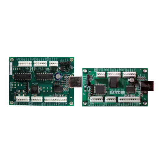
AR-BS1010-LLL AR-BS1010W-PTT AR-SS1010-LLL Board Size The AR-BS1010 boards, oriented as shown on this page, are 3.0 inches high by 2.25 inches wide. The AR-BS1010W boards, oriented as shown on this page, are 2.5 inches high by 2.4 inches wide. The AR-SS1010 boards, oriented as shown on this page, are 3.0 inches high by 1.75 inches wide. -
Page 69: Mounting Requirements-Bs1010
5 screw, which thus allows use of the standard #4 mounting spacers. Vertically, their centers are 2.75 inches apart, and horizontally they are 2.00 inches apart. Thus, when the board is positioned as shown above, their positions are: (0.125, 0.125), (1.625, 0.125), (0.125, 2.875), (1.625, 2.875) BS1010 Motor Controllers Peter Norberg Consulting, Inc. -
Page 70: Connector Signal Pinouts, Bs1010 And Ss1010
AN2, SI2, SO2, IO2. Then, on the bottom we have: a USB female connector on the bottom of the board. Finally, on the BS1010, going from top-right down, we have: X Motor connector (upper right) Y Motor connector (center) ... -
Page 71: Debugger Connector
4. Apply power to the board for at least 10 seconds (if the board is USB powered, wait until the 'LED' turns on). 5. Turn off power 6. Remove the PGC-PDG short 7. Reconnect your board as usual: it should now be at its factory default settings. BS1010 Motor Controllers Peter Norberg Consulting, Inc. -
Page 72: Ttl Limit Input And Reset
Y motor to go in the “negative” direction. Note that you may use the ‘T’ command (T – limit, slew switch control and motor driver enable) to change the response of the board to the slew inputs. BS1010 Motor Controllers Peter Norberg Consulting, Inc. -
Page 73: Board Status And Ttl Serial
IO2 is a generic TTL I/O signal, normally configured as a TTL input. It may be reconfigured as a TTL output through use of the ‘t’ command. BS1010 Motor Controllers Peter Norberg Consulting, Inc. -
Page 74: Bs1010W 19 Pin Sip Header
IO: +5V Board +5V IO: GND USB-B Serial (AR-BS1010 and AR-SS1010) On the AR-BS1010 and AR-SS1010, there is a standard USB-B female connector for use with a standard USB-A-B cable to the computer. BS1010 Motor Controllers Peter Norberg Consulting, Inc. -
Page 75: Bs1010 And Ss1010 Power Connector (Labeled Here Top-To-Bottom) And Motor Voltages
Description Ground for Vm 4.5-vMax volts, for the X and Y motors vMax = 34 volts for the BS1010 series of boards, and 26 volts for the SS1010 series of boards. Ground for Vc Normally configured as +6.5-15 volts for the logic circuits. -
Page 76: Bs1010W Power Connector (Labeled Here Top-To-Bottom) And Motor Voltages
BS1010 and SS1010 Power Option Jumper Configuration The BS1010 and SS1010 boards (NOT the BS1010W) have a 4 or 5 pin SIP header positioned beside the power connector which controls how power is routed to the logic part of the board. The jumper must be installed in one of the 4 positions shown, SS, DS, 5VO or USB. -
Page 77: Board Mounting And Cooling Considerations
Note that if the current requirements are over about 0.6 Amp/winding on the BS1010 or 0.2 amp/winding on the SS1010, if the motor supply voltage is above 15 volts, or if the windings are left on through use of the 'W' command, then fan- based cooling of the board is usually required. -
Page 78: Calculating Current And Voltage Power Supply Requirements
For example, if you are going to microstep (mode 3) a motor whose winding current has been calculated to be 0.4 amps, then your power supply needs to be able to supply 2 x 0.4, or 0.8 amps to drive that particular motor. BS1010 Motor Controllers Peter Norberg Consulting, Inc. -
Page 79: Determine The Voltage For Your Motor Power Supply
0.5 amps of current, then the motor voltage will be 0.5 * 12, or 6 volts. 4. Determine the logic supply requirements The logic supply normally requires 300 mA for the BS1010, SS1010 and BS1010W products. If you choose to operate a fan off of the on-board 5 volts in order to cool the system, or if you are going to tap the 5 volts for other external logic, you need to add in the current which is needed to operate the fan and the external logic. -
Page 80: Determine The Power Supplies You Will Be Using
Note that in the 5VO position, you will damage the board if your supply ever reaches or exceeds 6 volts, and the board will undergo a reset if the voltage ever drops (even as a spike) to 4.2 volts. BS1010 Motor Controllers Peter Norberg Consulting, Inc. -
Page 81: Board Jumpers
Page 81 Board Jumpers The BS1010 and SS1010 boards have one jumper, used to configure power input to the board. Power Selection Jumper - SS/DS/5VO/USB This jumper is used to select how the board is to be powered. It may be factory hard-wired (for volume orders), or it will be available as a jumper selection as needed. -
Page 82: Wiring Your Motor
(This designation affects only which commands are to be used to control the motors; no other functionality is changed.) They are wired as follows for the BS1010 and the SS1010 series of controllers (pins counting from top to bottom):... -
Page 83: Stepping Sequence, Testing Your Connection
For bipolar motors, the windings match the labels – that is to say, pins 2-3 are for winding B, and 4-5 are for winding A. Note that the unipolar motors will also match the labels, but it may be more difficult to identify the windings. BS1010 Motor Controllers Peter Norberg Consulting, Inc. -
Page 84: Determining Lead Winding Wire Pairs
(unfortunately, this test cannot show which is winding A and which is winding B through resistances alone). BS1010 Motor Controllers Peter Norberg Consulting, Inc. - Page 85 -- if the resistance between the common leads is very low (less than 10 ohms), such a connection exists and you must therefore operate using the regular unipolar wiring scheme. BS1010 Motor Controllers Peter Norberg Consulting, Inc.
-
Page 86: Sequence Testing
Turn off power to the board in between each test, so that power is not on while you change the wiring. For wires A, B, C, and D (where A, B, C, and D are initially connected to the WA1, WA2, WB1, and WB2 lines) try these orders: BS1010 Motor Controllers Peter Norberg Consulting, Inc. - Page 87 A B C D, rewire as B A D C. For the purposes of testing, the default power-on rate of 100 ½-steps/second should work with most motors. Otherwise, use the serial connection to define the precise rate needed. BS1010 Motor Controllers Peter Norberg Consulting, Inc.
-
Page 88: Single Motor, Double Current Mode Of Operation
2 times the normal rated current for the board. For example, a single 2 amp motor can be operated by our BS1010 board (which normally has a top current of 1 amp/winding/motor) if the board is configured as described in this section. -
Page 89: Wiring A Bipolar Motor For Double Current Mode
Single motor, double current mode of operation Page 89 Wiring a Bipolar motor for double current mode Motor Bipolar Motor Double Current Mode Connection To the BS1010 series of boards. BS1010 Motor Controllers Peter Norberg Consulting, Inc. -
Page 90: Motor Wiring Examples
All were purchased from Jameco (www.jameco.com). The following sections summarize some of the motors tested. The wiring diagrams shown are labeled for the BiStepA05 and SimStepA04. The BS1010 is identical. Unipolar Motors This section shows some unipolar motors which were used. -
Page 91: Jameco 151861 5 Volt, 0.55 Amp/Winding, 7.5 Deg/Step
Jameco 162026 12 Volt, 0.6 Amp/winding, 6000 g-cm, 1.8 deg/step This motor provides for 6000 g-cm(!) of holding torque, and has a manufacturing number of GBM 57BYGO84. Its wiring order is: Color BS1010 Black Orange Green Yellow Blue White BS1010 Motor Controllers Peter Norberg Consulting, Inc. -
Page 92: Jameco 169201 24 Volt, 0.3 Amp/Winding, 1.8 Deg/Step
Jameco 174553 12 Volt, 0.6 Amp/winding, 7.5 deg/step This motor has a manufacturing part number of NMB PM55L-048-NBC7. Its wiring is: Color BS1010 Black (common for Brown and Red) Brown Green Yellow Orange (common for Yellow and Green) BS1010 Motor Controllers Peter Norberg Consulting, Inc. -
Page 93: Bipolar Motors
The wiring of this unit is therefore: Color BS1010 <no connection> Yellow Black Gray <no connection> BS1010 Motor Controllers Peter Norberg Consulting, Inc. -
Page 94: Jameco 155459 12 Volt, 0.4 Amp, 2100 G-Cm, 1.8 Deg/Step
Yellow <no connection> Jameco 163395 8.4 Volt, 0.28 Amp, 0.9 deg/step This is a Scotts Valley 5017-935 stepper motor. It may be wired as: Color BS1010 <no connection> Yellow White Blue <no connection> BS1010 Motor Controllers Peter Norberg Consulting, Inc. -
Page 95: Jameco 168831 12 Volt, 1.25 Amp
BS1010 to overheat (and probably fail) after just a short period of use, if the BS1010 is configured for the default operation of running two motors at a time. We tested it with the wiring of:...
Need help?
Do you have a question about the BS1010 and is the answer not in the manual?
Questions and answers